
Loading...
Loading...
Loading...
Loading...
Loading...
Loading...
Loading...
Loading...
Loading...
Loading...
Loading...
Loading...
Loading...
Loading...
Loading...
Loading...
Loading...
Loading...
Loading...
Loading...
Loading...
Loading...
Loading...
Loading...
Loading...
Loading...
Loading...
Loading...
Loading...
Loading...
How an integrated application uses its QwantiFi MQTT credentials to talk to one device or many devices once those credentials have been distributed.
This guide is client-agnostic: it describes the MQTT concepts and message flow with pseudocode, so it applies to any MQTT client library (mqtt.js, MQTTnet, Paho, Eclipse Mosquitto clients, etc.).
A single integrated application credential lets one integrated application instance command every device it owns — there is no per-device credential to manage on the integrated application side.
A device has exactly one subscribe topic and one publish topic. It listens only for commands addressed to its own serial number and has no routing logic of its own.
A POS holds lists of publish and subscribe topics covering all the devices under its scope (a whole reseller, or a single merchant). It addresses each device by publishing to that device's topic and listens for each device's responses on a separate topic.
Commands and responses travel on different topic branches so a device never re-receives its own output and the integrated application is not fighting echo/recursion.
The mqttConfig object you were given at onboarding carries everything you need:
Example of a merchant-scoped credential (a reseller-wide credential looks the same but its username is pos-{reseller} and its topics span every merchant under that reseller). The scope is fixed at issue time — the integrated application does not select it:
The JWT is the password. Do not also send a separate password — the broker validates the JWT signature to authenticate you, then applies your authorization rules from its broker-side store, matched by your username.
Transport: trust port, not operatingMode. operatingMode is a coarse hint and is currently reported as mqtts regardless of environment. Decide TLS from the port you were issued and from what your onboarding contact told you the environment uses; if peerCommonName is populated, verify the server certificate against it.
Publish grant (what you may use): MagTek/13204/2026213/+/SendCommand
Actual command you publish (one device): MagTek/13204/2026213/TEST-001/SendCommand
Subscribe grant (what you may use): MagTek/13204/2026213/device/publish/+/MMSMessage and …/+/Status
The grant is leaf-specific: publishing is allowed only on the SendCommand leaf, and subscribing only on the MMSMessage and Status leaves — a broad …/{sn}/# will not match the grant and is denied. {% endhint %}
Open a standard MQTT connection using the credential fields:
Multiple POS terminals (lanes, stations) for the same merchant connect with the same username. The broker requires a unique clientId per live connection — if two clients use the same clientId, the broker disconnects the earlier one. Always append a per-terminal/per-process suffix:
The username is a safe shared identity; the clientId is what must be unique.
All topics follow the hierarchy:
Two distinct branches are used:
The device is authorized for its whole subtree MagTek/{r}/{c}/{sn}/# and listens on the concrete …/{sn}/SendCommand leaf — the command topic your POS credential is authorized to publish to.
The device publishes its output to the separate …/device/publish/{sn}/… branch — never back into its own command subtree — which is why command and response do not loop. It emits two event kinds: MMSMessage (transaction/message data) and Status.
To command one device with serial TEST-001 (reseller 13204, customer 2026213):
Subscribe for its responses (do this before sending, so you don't miss the reply). A device emits two event kinds, so subscribe to both leaves:
Publish a command to that device's command topic:
Handle the response on your message callback:
You have two equivalent strategies — choose per your routing needs.
Subscribe once per event leaf to the scope wildcard and receive every device's responses on a single handler:
You do not have to build those strings yourself — they are the last two entries of mqttConfig.subscribeTopics, already correct for your scope:
This is the recommended form for anything beyond a handful of devices: two subscriptions total, and devices onboarded later are picked up automatically with no resubscribe. Extract the device serial from the topic to know who replied:
To send, publish to each device's command topic:
Subscribe to each device's two response leaves individually — these all fall under your authorized scope wildcard, so the broker permits them:
Useful when different devices feed different handlers, or when you want the subscription set to mirror exactly the devices you manage.
Your credential's topic lists enumerate the devices provisioned to your scope at the moment it was issued — a convenient starting address book. Because authorization is a scope wildcard, you are not limited to that snapshot: devices added after you connected are reachable immediately by addressing the new serial (no new credential needed).
The cleanest way to enumerate them at runtime is , which returns a roster — one entry per device, each already pairing the serial with its topics — so you never parse serials out of topic paths. Alternatives: your own provisioning records, or re-fetching the flat lists via or .
Before sending to a device you have not heard from in a while, you can ask whether it currently holds a broker session, rather than publishing and waiting on silence — use . It reports connected, status (PENDING/PROVISIONED), and blocked.
MQTT is asynchronous — a response arrives as a separate message. To match a reply to the command and device that produced it:
By device: the response topic contains the device serial, so the topic itself tells you which device replied and which event kind it is.
By command: if you issue several commands to the same device, include a correlation token in your command payload (per the device protocol) and echo it in the response, or serialize commands per device.
Keep a per-device in-flight map keyed by serial (and correlation token if available) so concurrent operations across many devices do not get cross-wired.
The JWT in password is short-lived — 8 hours by default, though configurable per environment, so always drive your timer off expiresAt rather than a hard-coded 8. You were also handed a long-lived, opaque refresh token once, at onboarding (store it securely) — it is what lets the integrated application mint fresh JWTs on its own, with no portal involvement.
Refresh ahead of expiry. Before expiresAt, mint a fresh JWT (same scope, same username) with =, passing your username + refresh token. A good practice is to refresh at ~75–80% of the lifetime. This re-mints the JWT without rotating the refresh token.
Don't let the JWT lapse — the lookup endpoints require a live one. pos-topics-list, pos-device-list, and pos-device-status
For the full credential model behind refresh, see the .
Clean vs persistent session. A clean session means you must re-subscribe on every reconnect. A persistent session (clean=false with a stable clientId) lets the broker queue messages and retain subscriptions across brief disconnects. The clientId still has to be unique across concurrently live terminals.
Multiple terminals. Same username, different clientId each. They share the identity, JWT, refresh token, and authorization scope, so each terminal is authorized for every device under the scope. Partitioning devices across lanes is a client-side concern.
Payload framing is device-defined. The MQTT platform moves opaque bytes; the SendCommand
Scope examples use reseller 13204, customer 2026213, device TEST-001.
For the complete endpoint surface — request shapes, headers, and status codes — see the .
Connect checklist
Actual response topics (one device): MagTek/13204/2026213/device/publish/TEST-001/MMSMessage and …/TEST-001/Status
401pos-credentials/refreshReconnect with the new token. The broker checks the JWT at CONNECT time. An existing connection is not retroactively killed at the instant of expiry, but any reconnect requires a still-valid token.
Re-subscribe after reconnect unless you use a persistent session (see below).
Security. Treat the JWT like a password — never log it. Use TLS wherever the environment offers it. Both the JWT and the refresh token are bearer secrets.
broker
Broker host to connect to. Environment-specific — always take it from this field rather than hard-coding it.
port
Broker port (1883 plain, 8883 TLS are the usual choices). Environment-specific, like broker.
peerCommonName
{
  "broker": "<your-broker-host>",
  "port": 8883,
  "peerCommonName": "",
  "username": "pos-13204-2026213",
  "password": "<HS256 JWT>",
  "publishTopics":   ["MagTek/13204/2026213/TEST-001/SendCommand"],
  "subscribeTopics": [
    "MagTek/13204/2026213/device/publish/TEST-001/MMSMessage",
    "MagTek/13204/2026213/device/publish/TEST-001/Status",
    "MagTek/13204/2026213/device/publish/+/MMSMessage",
    "MagTek/13204/2026213/device/publish/+/Status"
  ],
  "operatingMode": "mqtts",
  "expiresAt": "2026-06-19T01:43:00Z"
}client = mqtt.connect({
host: mqttConfig.broker,
port: mqttConfig.port,
username: mqttConfig.username, // CONNECT username
password: mqttConfig.password, // CONNECT password = the JWT
clientId: makeUniqueClientId(mqttConfig.username),
tls: port_is_tls, // when port is a TLS port
expectedCommonName: mqttConfig.peerCommonName // verify against server cert
})makeUniqueClientId(username) = username + "-" + stationId + "-" + randomShortId()
// e.g. "pos-13204-2026213-lane1-9fa3"MagTek / {ResellerId} / {CustomerId} / {DeviceSN}Command (to device)
MagTek/{r}/{c}/{sn}/SendCommand
POS (and backend)
the device
client.subscribe("MagTek/13204/2026213/device/publish/TEST-001/MMSMessage", qos=1)
client.subscribe("MagTek/13204/2026213/device/publish/TEST-001/Status", qos=1)topic = "MagTek/13204/2026213/TEST-001/SendCommand"
payload = buildDeviceCommand(...) // device-protocol bytes — see note below
client.publish(topic, payload, qos=1)on_message(topic, payload):
if topic.startsWith("MagTek/13204/2026213/device/publish/TEST-001/"):
handleDeviceResponse("TEST-001", topic, payload)client.subscribe("MagTek/13204/2026213/device/publish/+/MMSMessage", qos=1) // merchant scope
client.subscribe("MagTek/13204/2026213/device/publish/+/Status", qos=1)
// reseller scope would be: "MagTek/13204/+/device/publish/+/MMSMessage" (and .../+/Status)filters = mqttConfig.subscribeTopics.slice(-2) // [ .../+/MMSMessage, .../+/Status ]
for topic in filters:
client.subscribe(topic, qos=1)on_message(topic, payload):
// topic = ".../device/publish/<SN>/<MMSMessage|Status>"
parts = topic.split("/")
sn = parts[parts.length - 2]
handleDeviceResponse(sn, topic, payload)for sn in mySerials:
client.publish("MagTek/13204/2026213/" + sn + "/SendCommand", buildCommand(sn), qos=1)for sn in mySerials:
client.subscribe("MagTek/13204/2026213/device/publish/" + sn + "/MMSMessage", qos=1)
client.subscribe("MagTek/13204/2026213/device/publish/" + sn + "/Status", qos=1)loop:
if now() > expiresAt - refreshMargin:
mqttConfig = POST /api/pos-credentials/refresh { username, refreshToken }
reconnectWith(mqttConfig)Send command to one device
MagTek/13204/2026213/TEST-001/SendCommand (publish)
Receive one device's responses
MagTek/13204/2026213/device/publish/TEST-001/MMSMessage and …/TEST-001/Status (subscribe)
Receive all merchant devices' responses
Expected TLS certificate common name (when using TLS). May be empty.
username
MQTT username — present in the CONNECT username field. Shared by all integrated application terminals in the same scope.
password
A short-lived HS256 JWT — present in the CONNECT password field. Used for authentication (signature + expiry); the authorization rules live broker-side, not in the token.
publishTopics
List of explicit per-device command topics — one …/{sn}/SendCommand for every device under your scope. Informational (your real grant is a broker-side scope filter). Empty when no devices are onboarded. No wildcard entry: MQTT forbids wildcards in a PUBLISH topic.
subscribeTopics
List of per-device response topics — for each device, its …/device/publish/{sn}/MMSMessage and …/device/publish/{sn}/Status — followed, last, by the two scope filters …/device/publish/+/MMSMessage and …/+/Status. Subscribe to that trailing pair to cover every device in your scope at once.
operatingMode
Transport hint (mqtts). Treat port and your TLS settings as authoritative — see the transport note below.
expiresAt
UTC instant the JWT stops being valid. Refresh before this.
Response (from device)
MagTek/{r}/{c}/device/publish/{sn}/MMSMessage and …/{sn}/Status
the device
POS (and dashboards)
MagTek/13204/2026213/device/publish/+/MMSMessage and …/+/Status (subscribe)
Receive all reseller devices' responses
MagTek/13204/+/device/publish/+/MMSMessage and …/+/Status (subscribe)
Command-scope grant (merchant)
MagTek/13204/2026213/+/SendCommand (broker rule, not sendable)
Document Number: D998200680-100
REGISTERED TO ISO 9001:2015
MagTek I 1710 Apollo Court I Seal Beach, CA 90740 I Phone: (562) 546-6400 I Technical Support: (888) 624-8350 www.magtek.com
Copyright © 2018 - 2024 MagTek, Inc. Printed in the United States of America
INFORMATION IN THIS PUBLICATION IS SUBJECT TO CHANGE WITHOUT NOTICE AND MAY CONTAIN TECHNICAL INACCURACIES OR GRAPHICAL DISCREPANCIES. CHANGES OR IMPROVEMENTS MADE TO THIS PRODUCT WILL BE UPDATED IN THE NEXT PUBLICATION RELEASE. NO PART OF THIS DOCUMENT MAY BE REPRODUCED OR TRANSMITTED IN ANY FORM OR BY ANY MEANS, ELECTRONIC OR MECHANICAL, FOR ANY PURPOSE, WITHOUT THE EXPRESS WRITTEN PERMISSION OF MAGTEK, INC.
MagTek®, MagnePrint®, and MagneSafe® are registered trademarks of MagTek, Inc. Magensa™ is a trademark of MagTek, Inc.
DynaFlex™, DynaFlex Pro™, DynaProx™, DynaFlex II SCRA™, DynaFlex II PED™, and DynaFlex II GO™ are trademarks of MagTek, Inc.
AAMVA™ is a trademark of AAMVA.
American Express® and EXPRESSPAY FROM AMERICAN EXPRESS® are registered trademarks of American Express Marketing & Development Corp.
D-PAYMENT APPLICATION SPECIFICATION® is a registered trademark to Discover Financial Services CORPORATION
MasterCard® is a registered trademark and PayPass™ and Tap & Go™ are trademarks of MasterCard International Incorporated.
Visa® and Visa payWave® are registered trademarks of Visa International Service Association.
ANSI®, the ANSI logo, and numerous other identifiers containing "ANSI" are registered trademarks, service marks, and accreditation marks of the American National Standards Institute (ANSI).
ISO® is a registered trademark of the International Organization for Standardization. UL™ and the UL logo are trademarks of UL LLC.
PCI Security Standards Council® is a registered trademark of the PCI Security Standards Council, LLC. EMV® is a registered trademark in the U.S. and other countries and an unregistered trademark elsewhere. The EMV trademark is owned by EMVCo, LLC. The Contactless Indicator mark, consisting of four graduating arcs, is a trademark owned by and used with permission of EMVCo, LLC.
The Bluetooth® word mark and logos are registered trademarks owned by Bluetooth SIG, Inc. and any use of such marks by MagTek is under license.
Google Play™ store, Google Wallet™ payment service, and Android™ platform are trademarks of Google Inc.
Apple Pay®, iPhone®, iPod®, Mac®, and OS X® are registered trademarks of Apple Inc., registered in the U.S. and other countries. iPad™ is a trademark of Apple. Inc. App StoreSM is a service mark of Apple Inc., registered in the U.S. and other countries. IOS is a trademark or registered trademark of Cisco in the U.S. and other countries and is used by Apple Inc. under license.
Microsoft®, Windows®, and .NET® are registered trademarks of Microsoft Corporation. NFC is governed by The NFC Forum.
All other system names and product names are the property of their respective owners.
MagTek warrants that the products sold pursuant to this Agreement will perform in accordance with
MagTek’s published specifications. This warranty shall be provided only for a period of one year from the date of the shipment of the product from MagTek (the “Warranty Period”). This warranty shall apply only to the “Buyer” (the original purchaser, unless that entity resells the product as authorized by MagTek, in which event this warranty shall apply only to the first repurchaser).
During the Warranty Period, should this product fail to conform to MagTek’s specifications, MagTek will, at its option, repair or replace this product at no additional charge except as set forth below. Repair parts and replacement products will be furnished on an exchange basis and will be either reconditioned or new. All replaced parts and products become the property of MagTek. This limited warranty does not include service to repair damage to the product resulting from accident, disaster, unreasonable use, misuse, abuse, negligence, or modification of the product not authorized by MagTek. MagTek reserves the right to examine the alleged defective goods to determine whether the warranty is applicable.
Without limiting the generality of the foregoing, MagTek specifically disclaims any liability or warranty for goods resold in other than MagTek’s original packages, and for goods modified, altered, or treated without authorization by MagTek.
Service may be obtained by delivering the product during the warranty period to MagTek (1710 Apollo Court, Seal Beach, CA 90740). If this product is delivered by mail or by an equivalent shipping carrier, the customer agrees to insure the product or assume the risk of loss or damage in transit, to prepay shipping charges to the warranty service location, and to use the original shipping container or equivalent. MagTek will return the product, prepaid, via a three (3) day shipping service. A Return Material
Authorization (“RMA”) number must accompany all returns. Buyers may obtain an RMA number by contacting MagTek Support Services at (888) 624-8350.
EACH BUYER UNDERSTANDS THAT THIS MAGTEK PRODUCT IS OFFERED AS-IS. MAGTEK MAKES NO OTHER WARRANTY, EXPRESS OR IMPLIED, AND MAGTEK DISCLAIMS ANY WARRANTY OF ANY OTHER KIND, INCLUDING ANY WARRANTY OF MERCHANTABILITY OR FITNESS FOR A PARTICULAR PURPOSE.
IF THIS PRODUCT DOES NOT CONFORM TO MAGTEK’S SPECIFICATIONS, THE SOLE REMEDY SHALL BE REPAIR OR REPLACEMENT AS PROVIDED ABOVE. MAGTEK’S LIABILITY, IF ANY, SHALL IN NO EVENT EXCEED THE TOTAL AMOUNT PAID TO MAGTEK UNDER THIS AGREEMENT. IN NO EVENT WILL MAGTEK BE LIABLE TO THE BUYER FOR ANY DAMAGES, INCLUDING ANY LOST PROFITS, LOST SAVINGS, OR OTHER INCIDENTAL OR CONSEQUENTIAL DAMAGES ARISING OUT OF THE USE OF, OR INABILITY TO USE, SUCH PRODUCT, EVEN IF MAGTEK HAS BEEN ADVISED OF THE POSSIBILITY OF SUCH DAMAGES, OR FOR ANY CLAIM BY ANY OTHER PARTY.
LIMITATION ON LIABILITY
EXCEPT AS PROVIDED IN THE SECTIONS RELATING TO MAGTEK’S LIMITED WARRANTY, MAGTEK’S LIABILITY UNDER THIS AGREEMENT IS LIMITED TO THE CONTRACT PRICE OF THIS PRODUCT.
MAGTEK MAKES NO OTHER WARRANTIES WITH RESPECT TO THE PRODUCT, EXPRESSED OR IMPLIED, EXCEPT AS MAY BE STATED IN THIS AGREEMENT, AND MAGTEK DISCLAIMS ANY IMPLIED WARRANTY, INCLUDING WITHOUT LIMITATION ANY IMPLIED WARRANTY OF MERCHANTABILITY OR FITNESS FOR A PARTICULAR PURPOSE.
MAGTEK SHALL NOT BE LIABLE FOR CONTINGENT, INCIDENTAL, OR CONSEQUENTIAL DAMAGES TO PERSONS OR PROPERTY. MAGTEK FURTHER LIMITS ITS LIABILITY OF ANY KIND WITH RESPECT TO THE PRODUCT, INCLUDING NEGLIGENCE ON ITS PART, TO THE CONTRACT PRICE FOR THE GOODS.
MAGTEK’S SOLE LIABILITY AND BUYER’S EXCLUSIVE REMEDIES ARE STATED IN THIS SECTION AND IN THE SECTION RELATING TO MAGTEK’S LIMITED WARRANTY.
IMPORTANT: YOU SHOULD CAREFULLY READ ALL THE TERMS, CONDITIONS AND RESTRICTIONS OF THIS LICENSE AGREEMENT BEFORE INSTALLING THE SOFTWARE PACKAGE. YOUR INSTALLATION OF THE SOFTWARE PACKAGE PRESUMES YOUR ACCEPTANCE OF THE TERMS, CONDITIONS, AND RESTRICTIONS CONTAINED IN THIS AGREEMENT. IF YOU DO NOT AGREE WITH THESE TERMS, CONDITIONS, AND RESTRICTIONS, PROMPTLY RETURN THE SOFTWARE PACKAGE AND ASSOCIATED DOCUMENTATION TO THE ADDRESS ON THE FRONT PAGE OF THIS DOCUMENT, ATTENTION: CUSTOMER SUPPORT.
TERMS, CONDITIONS, AND RESTRICTIONS
MagTek, Incorporated (the "Licensor") owns and has the right to distribute the described software and documentation, collectively referred to as the "Software."
LICENSE: Licensor grants you (the "Licensee") the right to use the Software in conjunction with MagTek products. LICENSEE MAY NOT COPY, MODIFY, OR TRANSFER THE SOFTWARE IN WHOLE OR IN PART EXCEPT AS EXPRESSLY PROVIDED IN THIS AGREEMENT. Licensee
may not decompile, disassemble, or in any other manner attempt to reverse engineer the Software. Licensee shall not tamper with, bypass, or alter any security features of the software or attempt to do so.
TRANSFER: Licensee may not transfer the Software or license to the Software to another party without the prior written authorization of the Licensor. If Licensee transfers the Software without authorization, all rights granted under this Agreement are automatically terminated.
COPYRIGHT: The Software is copyrighted. Licensee may not copy the Software except for archival purposes or to load for execution purposes. All other copies of the Software are in violation of this Agreement.
TERM: This Agreement is in effect as long as Licensee continues the use of the Software. The Licensor also reserves the right to terminate this Agreement if Licensee fails to comply with any of the terms, conditions, or restrictions contained herein. Should Licensor terminate this Agreement due to Licensee's failure to comply, Licensee agrees to return the Software to Licensor. Receipt of returned Software by the Licensor shall mark the termination.
LIMITED WARRANTY: Licensor warrants to the Licensee that the disk(s) or other media on which the Software is recorded are free from defects in material or workmanship under normal use.
THE SOFTWARE IS PROVIDED AS IS. LICENSOR MAKES NO OTHER WARRANTY OF ANY KIND, EITHER EXPRESS OR IMPLIED, INCLUDING, BUT NOT LIMITED TO, THE IMPLIED WARRANTIES OF MERCHANTABILITY AND FITNESS FOR A PARTICULAR PURPOSE.
Because of the diversity of conditions and PC hardware under which the Software may be used, Licensor does not warrant that the Software will meet Licensee specifications or that the operation of the Software will be uninterrupted or free of errors.
IN NO EVENT WILL LICENSOR BE LIABLE FOR ANY DAMAGES, INCLUDING ANY LOST PROFITS, LOST SAVINGS, OR OTHER INCIDENTAL OR CONSEQUENTIAL DAMAGES ARISING OUT OF THE USE, OR INABILITY TO USE, THE SOFTWARE. Licensee's sole remedy in
the event of a defect in material or workmanship is expressly limited to replacement of the Software disk(s) if applicable.
GOVERNING LAW: If any provision of this Agreement is found to be unlawful, void, or unenforceable, that provision shall be removed from consideration under this Agreement and will not affect the enforceability of any of the remaining provisions. This Agreement shall be governed by the laws of the State of California and shall inure to the benefit of MagTek, Incorporated, its successors or assigns.
ACKNOWLEDGMENT: LICENSEE ACKNOWLEDGES THAT HE HAS READ THIS AGREEMENT, UNDERSTANDS ALL OF ITS TERMS, CONDITIONS, AND RESTRICTIONS, AND AGREES TO BE BOUND BY THEM. LICENSEE ALSO AGREES THAT THIS AGREEMENT SUPERSEDES ANY AND ALL VERBAL AND WRITTEN COMMUNICATIONS BETWEEN LICENSOR AND LICENSEE OR THEIR ASSIGNS RELATING TO THE SUBJECT MATTER OF THIS AGREEMENT.
QUESTIONS REGARDING THIS AGREEMENT SHOULD BE ADDRESSED IN WRITING TO MAGTEK, INCORPORATED, ATTENTION: CUSTOMER SUPPORT, AT THE ADDRESS LISTED IN THIS DOCUMENT, OR E-MAILED TO
DEMO SOFTWARE / SAMPLE CODE: Unless otherwise stated, all demo software and sample code are to be used by Licensee for demonstration purposes only and MAY NOT BE incorporated into any production or live environment. The PIN Pad sample implementation is for software PIN Pad test purposes only and is not PCI compliant. To meet PCI compliance in production or live environments, a third-party PCI compliant component (hardware or software-based) must be used.
Rev Number
Date
Notes
100
September 24, 2024
Initial Release
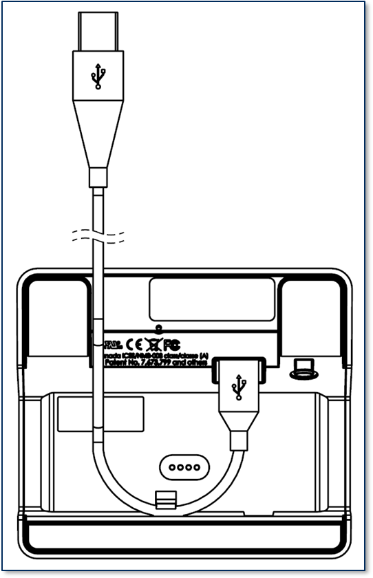
To connect via an interface listed in the Connection Type box, follow these steps.
For best results, use the cable that is included with the device.
Connect the USB-C end of the cable to DynaFlex device.
Figure - Connecting DynaFlex to a USB Host
If you plan to route the cable out the back of the device, route the cable through the cable management clip to change its direction. Even if you are not routing out the back, you may use the cable clip for strain relief, to help stabilize the mechanical connection when cardholders or operators move the device or the cable.
Route the cable in the desired direction (e.g., out the back, left, right, or down into the countertop).
Connect the other end of the USB cable to the host’s USB port.
As soon as the device starts receiving power through USB, it automatically powers on.
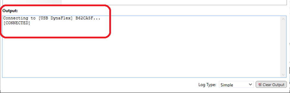
Launch the DynaFlex Utility and select DynaFlex device in the Device Type list, then press the connect button.
The Output log shows the status of the connection.
To disconnect the device, press Disconnect button.
The following instructions are for pairing the DynaFlex II GO to a PC.
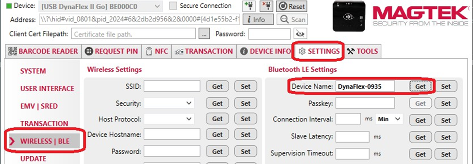
Launch the DynaFlex Utility to connect to the device by USB connection. Obtain Bluetooth LE Device name from selecting the Settings tab, Wireless/BLE menu, and at Bluetooth LE Settings press the Get button for Device Name
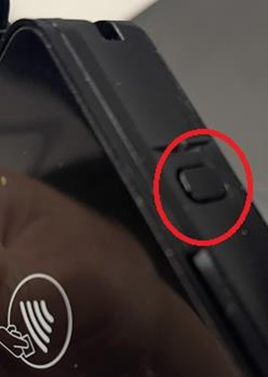
Place the device into Pairing Mode by pressing and holding the power button on device until 4 beeps and release the button. The 4th LED will blink green.
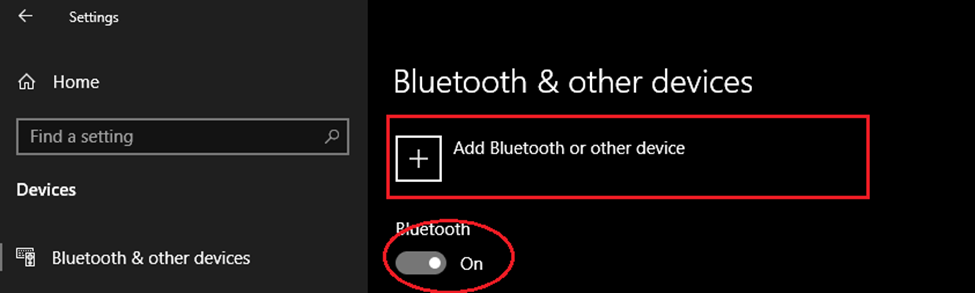
On the PC, open Settings and choose Bluetooth & other devices. Make sure the “Bluetooth” is turned ON . On the right panel, choose Add Bluetooth or other device.
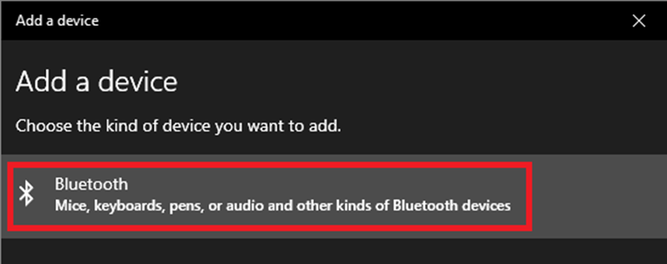
At the Add a device window, select Bluetooth.
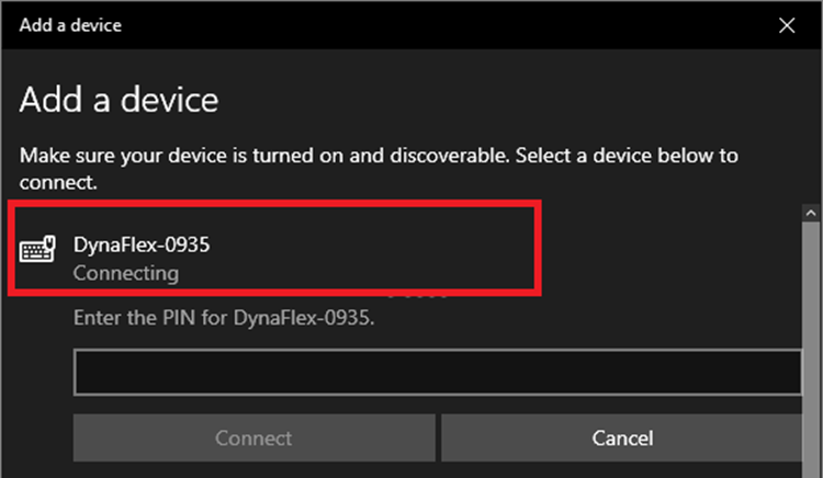
To pair, click on the device name that was been retrieved from DynaFlex Utility.
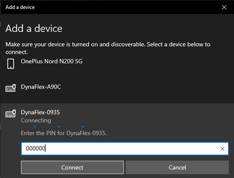
Enter the PIN, (“000000” by default), and press Connect .
Go back to DynaFlex Utility, disconnect the current USB connection.
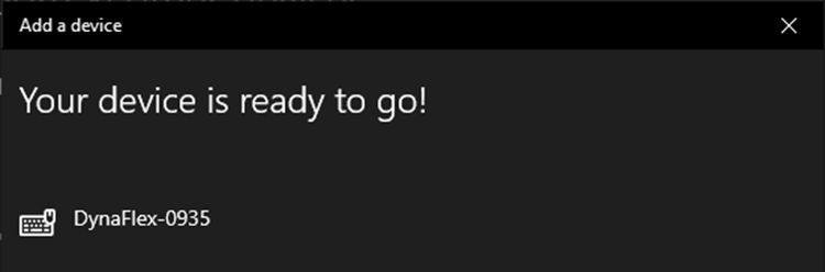
Click on Device list to find the added BLE device similar as below.



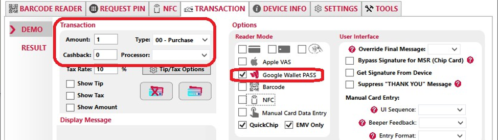
Select the Transaction tab, select the DEMO menu, seect the desired Transaction Type, and then select the Google Wallet PASS option.
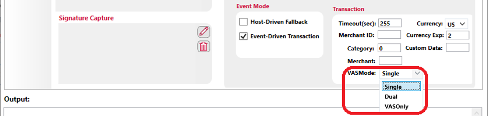
Select a VAS mode from the VASMode.
Single Mode: The device reads only VAS data from a tapped smartphone or reads EMV payment data from a tapped card. When the device sends ARQC to conclude the transaction, it only includes either EMV payment data in container FC for cards, or includes VAS data in FE container for smartphones.
Dual Mode: The device reads both VAS data and EMV payment data from a tapped smartphone or reads EMV payment data from a tapped card. When device sends ARQC to the host to conclude the transaction, it includes EMV payment data in container FC and includes VAS data, if available, in container FE.
VASOnly Mode: The device reads only VAS data from a tapped smartphone and does not read data from a tapped card. If the tapped smartphone does not support VAS, the device does not detect or read from the smartphone. When the device send ARQC to conclude the transaction, it includes VAS data in container FE and does not include EMV payment data in container FC.
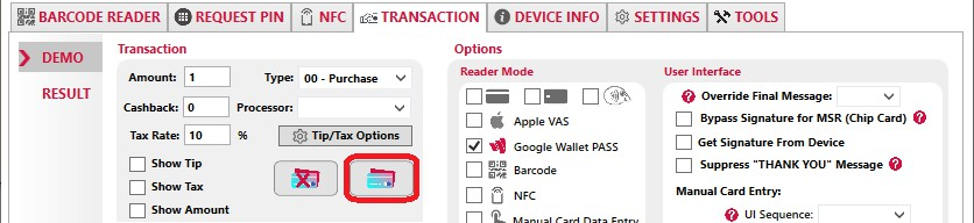
Press the Start EMV Transaction button to start the transaction.
Present the payment device with Google Wallet near the reader to continue the contactless transaction.
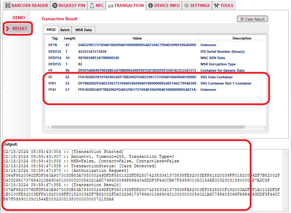
To view the transaction result after the transaction is completed, press RESULT menu. Parsed details can be seen in the ARQC tab, which shows details of the FE TLV object containing the Google Wallet VAS data. The status is displayed in the Outpit log
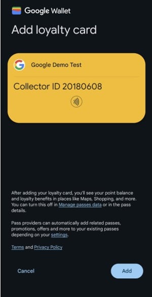
The following instructions is for installing a demo test Google Pass into an Android device. This pass is identified as Collector ID 20180608
Follow the link below. The link can be sent to an Android device by email.
If not already signed in, sign in with a Google account from the Android device.
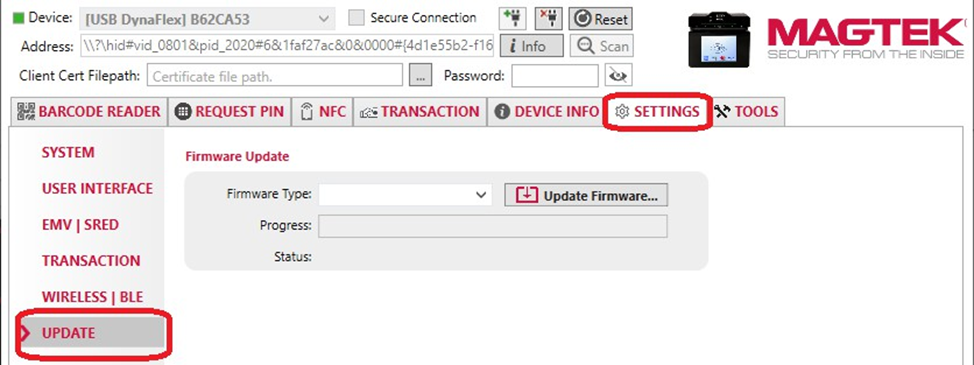
Press the Settings tab, and then select the Update menu.
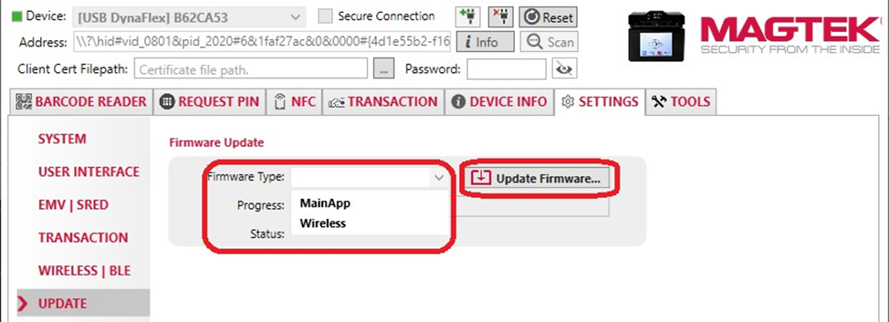
Select the Firmware Type, press the Update Firmware button. Navigate and select the firmware file.
Check the status displayed in the software.

How your integrated application software authenticates to the QwantiFi broker, and how it keeps that access alive on its own without a person logging into a portal.
This is the "why it works this way" companion to the Integration Guide, which covers the topics, the message flow, and the endpoint mechanics. Read this page to understand the credential model you are integrating against; read that one to write the code.
An integrated application instance talks to devices over the QwantiFi broker. To connect, it needs an MQTT credential. Unlike a physical device — which is issued a permanent username/password — an integrated application instance is issued a short-lived JSON Web Token (JWT) that it presents as its MQTT password.
Three ideas drive the whole design:
The platform is the credential authority. The broker does not mint, refresh, or revoke tokens — it only verifies them on connect. All issuance and refresh logic lives in the platform service.
Authentication and authorization are separate. The JWT answers "who are you?" The broker then answers "what may you do?" from a separate authorization store, looked up by the identity in the token. The token itself carries no permissions.
Identity is a scope, not a single terminal. A credential is keyed to a reseller (and optionally a customer/merchant), not to one physical lane. Every integrated application instance under the same scope shares one identity and one set of permissions.
When your credential is provisioned, a stable username is derived from your scope:
Reseller-wide — pos-{resellerId}, one identity covering every merchant under a reseller.
Customer-scoped — pos-{resellerId}-{customerId}, narrowed to a single merchant.
This username is the anchor for everything else: the JWT is issued for it, the broker's permission rules are keyed by it, and an audit record is stored under it. Because the identity is a scope, multiple integrated application terminals can run concurrently under the same username. Each must pick a distinct per-connection clientId so the broker does not treat them as the same session — the shared username is the identity, not the connection.
The issued JWT is authentication-only: it asserts the username and carries an expiry, signed with HS256 using a secret the broker also holds. On connect, the broker checks the signature and the expiry — nothing else. The token deliberately contains no permission rules. Its lifetime is 8 hours by default and is configurable per environment, so drive your refresh timer off the expiresAt you were handed rather than a hard-coded number.
Separately, a small, least-privilege set of permission rules is written into the broker's authorization store, keyed by your integrated application username. These grant exactly two things, each as a single scope-wide pattern rather than a per-device list:
the topics you may publish to (commands toward devices in your scope), and
the topics you may subscribe to (responses coming back from those devices).
Because the grant is a scope-wide pattern, you are automatically authorized for any device that appears or disappears under your scope later — no per-device maintenance, and no re-provisioning when a device is added.
A successful provisioning hands you everything needed to connect — broker coordinates, your username, the JWT to use as the password, the topic patterns you are allowed to use, and the time the JWT expires plus a refresh token. The JWT itself is never stored on the platform side; only audit metadata is kept (who, what scope, when, expiry).
At onboarding, alongside the JWT, you receive a long-lived, opaque refresh token. It is a 256-bit high-entropy random string with no internal structure (not a JWT) and carrying no claims. Only a salted hash of it is stored on the platform side, never the token itself. The plaintext is returned to you exactly once, at issuance. This means a read of the platform's data store does not expose any usable refresh token; the platform can verify a token you present (by hashing it and comparing in constant time) but can never reproduce one.
If you lose it, it cannot be recovered — only re-issued through onboarding. Store it durably.
When your JWT is near expiry, call with your username and refresh token. The presented token is hashed, compared against the stored hash, and if it matches and is still valid, a fresh JWT with a new expiry is minted and returned. Swap it in and reconnect.
Because the refresh endpoint sits on the public gateway, the refresh token is not the only thing standing between an attacker and a fresh credential. You must also present your current MQTT JWT as an Authorization: Bearer token on the refresh call. This proves the caller recently held a legitimately-issued credential, not merely a refresh token. Two properties make this practical:
Expired tokens are accepted here. The whole point of refresh is to renew a credential that is about to expire or has just expired, so the JWT's signature is validated but its expiry is deliberately ignored — on this endpoint only. Instead the token's age is bounded: a JWT issued more than 90 days ago is refused. Since the issued-at is re-stamped on every refresh, an actively-refreshing integrated application always passes, while an ancient leaked token does not.
The identity must match. The JWT's username claim must equal the username being refreshed, so a valid token for one scope cannot be used to refresh another.
Refresh does not rotate the refresh token. The same refresh token keeps working for repeated refreshes, which is what lets an integrated application that was offline past its JWT's expiry come back on its own. The refresh response returns "refreshToken": null — that is expected; keep the token you already hold and do not overwrite it with the null.
Re-onboarding does rotate it. If the portal re-provisions your scope, a brand-new refresh token is issued and the previous one stops working. Because the identity is shared per scope, this affects all integrated application instances under that scope.
The refresh token is issued with 90 days of life, and each successful refresh slides its expiry: if fewer than 60 days remain it is pushed back out to 60 days from now; if more remain it is left alone. The slide only ever extends — it never shortens a longer window, and it cannot revive an already-expired or revoked token. The practical effect: an integrated application that refreshes on schedule never falls below 60 days and never needs re-onboarding, while one that stays dark past that window lapses naturally.
A refresh attempt is refused when any of these hold: the access-token factor is missing, malformed, wrongly-signed, older than 90 days, or for a different username; the username is unknown; the refresh token does not match; the refresh token has expired; or your scope has been revoked (§5). Two 401 responses are distinguishable, and it is worth branching on them:
Persist the refresh token durably and atomically (write-then-rename), so a crash never leaves it half-written.
Refresh proactively, with margin — around 75–80% of the JWT lifetime is a good trigger. This is also what keeps the sliding window from lapsing.
Tolerate clock skew and retry transient failures (502, 503) with backoff.
Access can be withdrawn by whoever issued your credentials — a decommissioned terminal, a merchant offboarding, or a credential believed compromised. This is an operator action on the issuing side; there is no endpoint for it on the integrated application-facing surface. What you would observe:
Refresh stops working, returning {"error":"Invalid username or refresh token."}.
Live connections are disconnected, and reconnecting is blocked — even with a JWT that has not expired yet. That block lifts on its own once the JWT would have expired anyway.
Publishes and subscribes stop being authorized, because the permission rules for your scope are removed.
Withdrawal comes in two flavors. The default is reversible: if it was done in error, access can be restored in place, and your integrated application simply refreshes with the original refresh token it still holds and reconnects — no re-onboarding. The stricter form is permanent, appropriate when a token may be compromised; restoring access then requires full re-onboarding through the portal. In either case, the correct client behavior is the same: stop retrying, surface the state, and contact whoever issued your credentials.
Short-lived JWTs keep blast radius small and require no revocation list for the common case — tokens simply expire. Refresh tokens let an unattended integrated application stay alive without a human in the loop, while hash-only storage keeps a refresh-token leak from a database read off the table. Splitting authentication (the token) from authorization (the rules the broker consults live) is the single decision that makes instant withdrawal of access possible at all — and pairing it with a self-expiring connection block means it takes effect immediately without leaving lasting residue on a reusable scope identity. Sliding the refresh token's expiry on every use closes the last gap: an actively-running integrated application is never dragged back through a portal on the calendar's say-so, while a credential nobody is using still lapses on schedule.
Keep one clean fallback: if a refresh is ever hard-rejected (expired or revoked), stop retrying and surface a "needs re-onboarding" state rather than hammering the endpoint.
Treat both secrets as passwords. Never log the JWT or the refresh token.
{"error":"Unauthorized."}
The JWT factor failed.
Usually recoverable — refresh and retry once.
{"error":"Invalid username or refresh token."}
The refresh-token factor failed — wrong, expired, or revoked.
Not recoverable by retrying. Stop and surface a "needs re-onboarding" state.

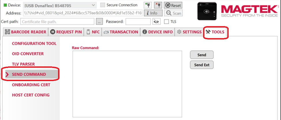
Select the Tools tab , and select the Send Command menu.
Below the Output box, change the Log Type to All Messages . Because the Output box auto scrolls after each command sent, the bottom displays the response referenced in these instructions.
Enter the following sequence of commands into the Raw Command text box
Set Protection Key Command
Response
Set Your Long Term Key Command
Response
Retrieve your key version Command
Response
Set Collector ID Slot 1 with value Command: “DF7C083230313830363038DF7D0103”
Response
Set Google Wallet Smart Tap POS Capability Command: (this sample set value to 08140300)
Response
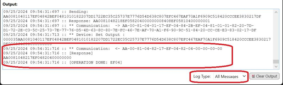
AA0081040117EF04842BEF0481010182207DD1722EC35C25737E7776D54D638C807EFC 467EAF70A1F6909C518420CCCEE3830217DFCommunication: <- AA-00-81-04-82-17-EF-04-82-04-00-00-00-00AA0081040118EF05848196EF0581010182040000000183020079858180B402AA3EC2EC 15DE2DCF8B06C75038DD0CBDA17C03FE6A71DBF2757A6CD050C39B99E2E190FC11C80E B07F0E6E1CA4B19A2FCEF4D35C48E0CF545045FC5F1E5C2973A8A8A05B33EBABD1D9A8 FE6CBC7E55A1083AD3CB00B452504015A96A82E3F0F49ACE94F20622251705071B73A5 6E8DAD2B971CD8865ACCB66A169DF0BEF88602BB2ECommunication: <- AA-00-81-04-82-18-EF-05-82-04-00-00-00-00-84-08-EF-05-81-04-00-00-00-01AA008104010AEF058405EF05810100Communication: <- AA-00-81-04-82-0A-EF-05-82-04-00-00-00-00-84-08-EF-05-81-04-00-00-00-01AA0081040110D1118429D11181072B06010401F6098501018919E117E115E113E111D0 0FDF7C083230313830363038DF7D0103Communication: <- AA-00-81-04-82-10-D1-11-82-04-00-00-00-00-84-82-00-29-D1-11-81-07-2B-06-01-04-01-F6-09-85-01-01-89-19-E1-17-E1-15-E1-13-
E1-11-D0-0F-DF-7C-08-32-30-31-38-30-36-30-38-DF-7D-01-03AA008104010BD111841ED11181072B06010401F609850101890EE10CE10AE108E106DA 0408140300Communication: <- AA-00-81-04-82-0B-D1-11-82-04-00-00-00-00-84-82-00-1E-D1-11-81-07-2B-06-01-04-01-F6-09-85-01-01-89-0E-E1-0C-E1-0A-E1-08-E1-06-DA-04-08-14-03-00Due to Payment Card Industry (PCI) certification requirements, the device must automatically reset at least once every 24 hours. This is required for security purposes, so that the device can reinitialize memory and perform a self-test. Host software developers and potentially end users should be aware of this.
By default, the device will automatically reset 23 hours after it boots up and it will attempt to send a warning notification message to the host 3 minutes before the reset occurs.
The default behavior is adjustable. See the following for more information:
Device Reset Will Occur Soon notification in
One way the host software could handle receiving a device reset-will-occur notification:
Cancel any operation that is in process (for example, a transaction) if it is unlikely to end before the reset.
Optionally send instead of waiting for the automatic reset to occur.
Re-connect with the device and re-start any operation that was in process.
The purpose of locking a device is to disable most of the device’s functionality for use cases that need this extra layer of security. When a device is locked, it will reject all commands except for a few. Use of the device lock feature is optional. It is not required by PCI.
The device lock state can be either unlocked or locked. The device lock state can be retrieved by getting a property.
The device lock state can be changed by setting a secure property or it can be changed with a command that requires knowledge of the device lock passcode.
The device can be configured to always have the device lock state set to locked after a reset or power cycle by setting a property.
If the device has a display and the device is locked, the welcome screen will display “WELCOME” “Device is Locked”. This screen can be customized.
Commands and properties to manage the device lock feature:
Only the following commands are allowed when the device lock state is set to locked:
The device lock passcode can be changed by setting a secure property or it can be changed with a command that requires knowledge of the current device lock passcode.
For more information on Google Wallet Smart Tap see document D998200597 DynaFlex II Go Programmer’s Manual (COMMANDS).
Property 1.1.1.1.1.10 Google Smart Tap Collector ID Slot 1
Property 1.1.1.1.1.11 Google Smart Tap Collector ID Slot 2
Property 1.1.1.1.1.12 Google Smart Tap Collector ID Slot 3
Property 1.1.1.1.1.13 Google Smart Tap Collector ID Slot 4
Property 1.1.1.1.1.14 Google Smart Tap Collector ID Slot 5
Property 1.1.1.1.1.15 Google Smart Tap Collector ID Slot 6
Property 1.1.1.1.1.1A Google Smart Tap POS Capability
The section uses the following sample values for demonstration purposes. Keys, Collector ID, and Capability will need to be replaced with actual values during integration.
(Protection Key - Key 0)
(Google Sample Key - Key 1)
Response
With value DF7C083230313830363038DF7D0103
This sample sets value to 08140300
7DD1722EC35C25737E7776D54D638C807EFC467EAF70A1F6909C518420CCCEE330770201010420826D17E50767B165B0E4D9E332F8D1D1E20224284FB4DAF1E50A03246E70797D A00A06082A8648CE3D030107A14403420004721C978FCEBDCDF98A8518BDC4FEDFD802B4EE4 128E2513B665593375E238786014E7CBE8511915DC5337AF57DCD248F2653C7A6AAAEE6913096 FD71C85BC4D7AA0081040117EF04842BEF0481010182207DD1722EC35C25737E7776D54D638C807EFC467EAF70 A1F6909C518420CCCEE3830217DFAA00
[81] [4] 0117EF04
[84] [43]
EF0481010182207DD1722EC35C25737E7776D54D638C807EFC467EAF70A1F6909C5184 20CCCEE3830217DF
EF04
[81] [1] 01
[82] [32]
7DD1722EC35C25737E7776D54D638C807EFC467EAF70A1F6909C518420CCCEE3 (AES
Key : Key 0)
[83] [2] 17DF (CRC for content of Key
0) CRC16_MCRF45X(7DD1722EC35C25737E7776D54D638C807EFC467EAF70A1F6909C
518420CCCEE3)AA0081040118EF05848196EF0581010182040000000183020079858180B402AA3EC2EC15DE2DCF8 B06C75038DD0CBDA17C03FE6A71DBF2757A6CD050C39B99E2E190FC11C80EB07F0E6E1CA4B 19A2FCEF4D35C48E0CF545045FC5F1E5C2973A8A8A05B33EBABD1D9A8FE6CBC7E55A1083AD
3CB00B452504015A96A82E3F0F49ACE94F20622251705071B73A56E8DAD2B971CD8865ACCB66 A169DF0BEF88602BB2EAA00
[81] [4] 0118EF05
[84] [150]
EF0581010182040000000183020079858180B402AA3EC2EC15DE2DCF8B06C75038DD0C BDA17C03FE6A71DBF2757A6CD050C39B99E2E190FC11C80EB07F0E6E1CA4B19A2FCEF4
D35C48E0CF545045FC5F1E5C2973A8A8A05B33EBABD1D9A8FE6CBC7E55A1083AD3CB00 B452504015A96A82E3F0F49ACE94F20622251705071B73A56E8DAD2B971CD8865ACCB6 6A169DF0BEF88602BB2E
EF05
[81] [1] 01
[82] [4] 00000001
[83] [2] 0079
[85] [128]
B402AA3EC2EC15DE2DCF8B06C75038DD0CBDA17C03FE6A71DBF2757A6CD050C39B99E2
E190FC11C80EB07F0E6E1CA4B19A2FCEF4D35C48E0CF545045FC5F1E5C2973A8A8A05B 33EBABD1D9A8FE6CBC7E55A1083AD3CB00B452504015A96A82E3F0F49ACE94F2062225
1705071B73A56E8DAD2B971CD8865ACCB66A169DF0BEF8 ( Encrypted
Key AES(Key 1) with Key 0)
[86] [2] BB2E (CRC for encrypted
key) CRC16_MCRF45X(B402AA3EC2EC15DE2DCF8B06C75038DD0CBDA17C03FE6A71DB F2757A6CD050C39B99E2E190FC11C80EB07F0E6E1CA4B19A2FCEF4D35C48E0CF545045 FC5F1E5C2973A8A8A05B33EBABD1D9A8FE6CBC7E55A1083AD3CB00B452504015A96A82 E3F0F49ACE94F20622251705071B73A56E8DAD2B971CD8865ACCB66A169DF0BEF8)
PRIVATE
Key 30770201010420826D17E50767B165B0E4D9E332F8D1D1E20224284FB4DAF1E50 A03246E70797DA00A06082A8648CE3D030107A14403420004721C978FCEBDCDF98A851 8BDC4FEDFD802B4EE4128E2513B665593375E238786014E7CBE8511915DC5337AF57DC D248F2653C7A6AAAEE6913096FD71C85BC4D7
Encrypted
LTPK B402AA3EC2EC15DE2DCF8B06C75038DD0CBDA17C03FE6A71DBF2757A6CD050C3 9B99E2E190FC11C80EB07F0E6E1CA4B19A2FCEF4D35C48E0CF545045FC5F1E5C2973A8 A8A05B33EBABD1D9A8FE6CBC7E55A1083AD3CB00B452504015A96A82E3F0F49ACE94F2 0622251705071B73A56E8DAD2B971CD8865ACCB66A169DF0BEF8
CRC for Key BB2E
AA008104010AEF058405EF05810100AA00
[81] [4] 010AEF05
[84] [5] EF05810100
EF05
[81] [1] 00 ( Get Key version)AA008104820AEF058204000000008408EF05810400000001AA00
[81] [4] 820AEF05
[82] [4] 00000000
[84] [8] EF05810400000001
EF05
[81] [4] 00000001AA0081040110D1118429D11181072B06010401F6098501018919E117E115E113E111D00FDF7C0832 30313830363038DF7D0103AA00
[81] [4] 0110D111
[84] [41] D11181072B06010401F6098501018919E117E115E113E111D00FDF 7C083230313830363038DF7D0103
D111
[81] [7] 2B06010401F609
[85] [1] 01
[89] [25] E117E115E113E111D00FDF7C083230313830363038DF7D0103
DF7C [08] 3230313830363038 Collector ID
DF7D [01] 03 (Type)AA008104010BD111841ED11181072B06010401F609850101890EE10CE10AE108E106DA040814030 0AA00
[81] [4] 010BD111
[84] [30]
D11181072B06010401F609850101890EE10CE10AE108E106DA0408140300
D111
[81] [7] 2B06010401F609
[85] [1] 01
[89] [14] E10CE10AE108E106DA0408140300EMV acceptance is how your host runs a chip (contact) or contactless EMV sale on a DynaFamily reader. The reader runs the EMV kernel and communicates with the card; your host orchestrates the transaction over the MMS command set — starting it, responding to the reader's prompts, forwarding the ARQC to your processor, and returning the result. This guide walks the full flow on the MMS command path and links to the commands, notifications, and data objects that implement each step.
The work is split between the reader and your host:
The reader runs the EMV kernel, talks to the card, and encrypts cardholder data at the point of read (SRED).
Your host starts the transaction, answers the reader's requests, forwards the ARQC to your processor, and returns the response.
There are two integration surfaces for this same flow. This guide covers the MMS command set directly. The Universal SDK wraps the identical flow in method calls and events — if you integrate through the SDK, the steps below still describe what happens underneath. (The .NET EMV Transaction Flow sample in the iDynamo manual shows the SDK surface.)
One behavior to note up front: readers with a display (e.g., the PED's touch screen) show cardholder prompts themselves. Readers without a full display, including the DynaFlex II Go, delegate those prompts to your host by sending ; your host shows the message or collects the selection. Watch for that difference throughout.
The reader is connected over USB or Bluetooth LE.
See
Keys are injected and you can decrypt output.
See
A typical contact or contactless sale runs as follows. Your host drives it with Start Transaction and reacts to the reader's notifications:
(Optional) Early card presentation. If the cardholder taps or inserts before you start, the reader sends to tell your host to start a transaction now.
Host starts the transaction. Send with the amount and type (transaction TLV, tag 86: 9C, 9F02, 5F2A), the interfaces to enable (Reader Options, tag A3), a timeout (tag 82), and the flow-control bitmask (tag 84).
Use this when the issuer must authorize online in real time.
Your host processes the ARQC, sends it to the processor, receives the ARPC, and returns it to the reader with .
The reader applies the issuer response, finishes with the card, and sends reporting the kernel outcome (Approved or Declined).
The result shows on-device on a display reader; on the the reader sends so your host can display it.
The recommended flow for most retail — it minimizes how long the card stays in the reader.
The reader builds its own internal ARPC (tag 8A = Z3) and completes immediately with ("Quick Chip Deferred"), so the cardholder can remove the card right away.
Your host then processes the ARQC, sets the final amount, and coordinates with the processor out-of-band. The reader is not involved in the final approve/decline, so you display the result yourself (via on a display reader, or your own UI on the Go).
Select it with the Transaction Flow bit in tag 84
The transaction carries EMV data as TLV objects, each documented once in Data types & shared TLV objects. The ones you'll handle most:
When you take a transaction online, you forward the ARQC to your processor and return the ARPC via . Two things to know:
Parts of the data are encrypted. Portions of the EMV ARQC and EMV Batch Data objects are SRED-encrypted. To use them, your host must first determine which key was used, then decrypt.
See .
You can avoid handling clear PAN. Magensa's service lets you send the encrypted transaction straight to a processor without exposing cardholder data in your environment
Both run the flow above; enable each interface in Reader Options (tag A3) on .
Contactless payments (tap-to-pay, mobile wallets) follow the same ARQC/ARPC flow.
NFC tags (non-payment) are different: the reader reports the card type and UID via and produces no ARQC or Batch data — you continue with pass-through commands.
See .
The kernel's behavior is controlled by configuration files you load onto the device:
, , and control the contact and contactless kernels.
enable Offline Data Authentication.
Load them using the file-operations commands and the file-type definitions in the data-object pages above.
To clear or reset a configuration, load the file type with EMPTY
Your device and payment application must be L3-certified with each processor. Dyna-family readers share a common EMV kernel, so certifying one family member can carry to the others, and Quick Chip is included in .
For the full strategy and the discovery questions to scope your certification, see .
EMV configuration is loaded (Terminal, Processing, Entry Point, and CA public keys).
See EMV Configuration below.
You've chosen a flow — Quick Chip or full EMV (see the fork below).
Card presented. The reader sends 0x0101 - Transaction Information Update reporting the payment technology and a Card Event.
Application selection (if needed). If the card supports more than one application, a display reader prompts directly; the device sends 0x1803 - Host Action Request, and your host replies with 0x1802 - Report Cardholder Selection.
ARQC produced. The reader sends 0x0101 again reporting a Data Update / ARQC Update, with the EMV ARQC object attached.
Completion depends on the flow you chose:
Files that control kernel behavior (see ).
Required for Offline Data Authentication (ODA).
AmEx contactless DRL handling.
See Magensa Services.
The host uses this command to provide a cardholder selection to the device when the device itself does not have a display or inputs to prompt the cardholder for a selection.
All Configuration Object Types can be found in Section.
Object
Description
The authorization request you forward to the processor.
The issuer response you return via Resume Transaction.
Command
Description
The host uses this command to start a payment transaction.
The host uses this command to provide the device with additional/modified data to resume a transaction that is currently paused.
Notification
Description
During a transaction.
Upon completion of a transaction
Type
Description
Information on how the device formats ARQC messages.
Information on how the device formats ARPC messages,
Guide
Description
This section covers how DynaFamily readers protect cardholder data and manage keys.
DynaFamily readers with a contactless interface can exchange commands directly with NFC tags and MIFARE cards through pass-through commands and can present themselves as a card to another reader through NFC card emulation.
Clearing/settlement data returned at completion.
The host can use this command to cancel a transaction in progress that it initiated using Start Transaction.
This notification requests that the host take action during operations involving the device’s User Interface modules.
Information on the device formats EMV batch data, such as merchant data and pre-defined EMV batch data tags.
Pursuing an L3 Certification (Level 3 Certification) with an EMV (Europay, Mastercard, Visa) payment processor involves several steps.
This section provides information about developing an iOS app that interfaces with the device via the USB connector using iPod Accessory Protocol (iAP2). For sample code and other supporting materials, see
To develop host software for an iOS host that connects to the device, you must know the following device properties, which are specified by the purchaser when ordering, and loaded by the manufacturer:
Apple iAP2 AppBundleID, also known as the SDK Protocol, usually in the form of a reverse DNS string unique to the host software developer or the device purchaser.
The host software should initiate a connection to the device using the iOS SDK’s ExternalAccessory Framework (for sample code, see Apple’s EADemo app). Upon establishing the connection, the host can begin exchanging data with the device.
File operations let your host move files to and from the reader — firmware images, EMV configuration files, certificates, and more. All of them use the File Operations command group and share the Common File Structure format. The most common file operation is updating firmware, covered first below.
Firmware images are signed by MagTek and delivered as a Firmware File Type object. There are two ways to apply one — a code path and a Windows utility.
Get the signed image. Obtain the firmware file for your device (see Getting firmware files below).
Send it to the device with 0xD801 - Load Firmware File, supplying the image type (boot loader, main app, Wi-Fi, or BLE module), a SHA-256 hash of the image, the payload, and a Load Option (Default or Auto Commit). The device must have more than 5% battery or it won't run the command.
The device validates and authenticates the signed image.
Commit the image:
If you sent Auto Commit, the device commits automatically.
Otherwise (Default mode), commit it with .
The device reports the result and resets: or. If the image is already current, the device sends .
If you don't need to script it, MagTek's Windows utility performs the same update through a GUI — see
The same command group handles non-firmware files — for example loading EMV configuration or certificate files, or retrieving files from the device:
For how files are framed, see About Files and the Common File Structure data object. Loading and erasing EMV configuration files specifically is covered in EMV acceptance.
To read the device's current firmware before or after an update, use the Firmware Identification Information properties.
Firmware images and the Windows utility are downloads, not part of this guide — find the files for your device in .
Read a file's metadata without downloading it.
Remove a file.
The host uses this command to start sending secured files to the device for storage or processing. It is similar to Start Send File to Device (Unsecured), but is used to send a different subset of file types that impact device security and require some form of authentication from the host.
The host uses this command to start sending unsecured files to the device for storage or processing. It is similar to Start Send File to Device (Secured) but is used to send a different subset of file types that do not impact device security.
`The host uses this command to request a file stored on the device. File types include standard files (images and certificates), MagTek custom files (configuration, firmware), and in some cases even large data blob output (such as signature capture data).
The host uses this command to request the file information of a file stored on the device. File types include standard files (images and certificates), MagTek custom files (configuration, firmware), and in some cases even large data blob output (such as signature capture data).
The host uses this command to request the deletion of a file stored on the device.
Section
Information
Send a file that must be sent securely.
Send a file that doesn't require a secure channel.
Section
Information
The host uses this command to send a firmware image file, signed by MagTek, to the device as the first step in updating firmware.
The host uses this command to commit a file previously uploaded using Command 0xD801 into the device’s permanent memory after the device has authenticated the file.
Section
Information
This notification reports the successful completion of firmware update operations the host initiated using Load Firmware File and Commit Firmware from File
This notification reports the failure of a Firmware Update command the host initiated using Load Firmware File and Commit Firmware from File.
Section
Information
Guide to loading EMV config files
Retrieve a file from the device.
The host uses this command to request a file stored on the device. File types include standard files (images and certificates), MagTek custom files (configuration, firmware), and in some cases even large data blob output (such as signature capture data).
This notification reports Firmware is up to date for host initiated Load Firmware File.
Understand the benefits DynaCast, NFC Card Emulation, offers and the business use cases.
DynaCast delivers receipts, access, and links directly to a user’s phone.
How to expand the use of NFC Card Emulation technology with MagTek DynaFlex II Go and DynaProx and add revenue building value to your application offering.
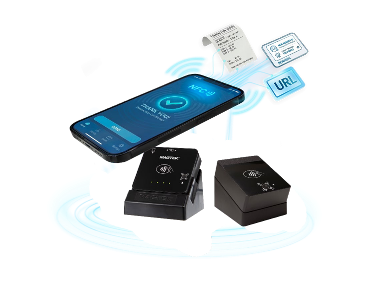
DynaCast is NFC Card Emulation technology integrated into MagTek DynaFlex II Go and DynaProx devices. It delivers significant value at the point-of-sale and the point-of-interaction by seamlessly connecting users to personalized digital experiences via custom URLs. It supports a wide variety of use cases, including instant loyalty program enrollment, digital product information, warranty registration, customer feedback collection, social media engagement, flexible payment solutions, personalized upselling, order tracking, subscription services, charity donations, digital business cards, event invitations, instant software downloads, product recall notifications, queue management, and immersive AR/VR experiences.
For merchants, this technology reduces costs associated with physical receipts and marketing materials, provides frictionless customer engagement without requiring app downloads, and facilitates comprehensive data collection for analytics. It significantly enhances the customer experience through personalized and timely interactions, increases opportunities for upselling, strengthens brand loyalty, aligns with sustainability initiatives, and helps prevent fraud by eliminating easily counterfeited printed coupons.
Consumers benefit through enhanced convenience, personalized offers, immediate access to relevant information, improved security and privacy, and engaging, interactive experiences optimized for mobile devices. The solution also aligns with consumer preferences for sustainability and provides instant support and resolution channels, significantly elevating the overall shopping experience.
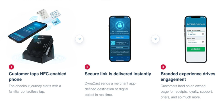
Unlock instant, engaging digital interactions at the point-of-sale and point-of-interaction with MagTek DynaFlex II Go and DynaProx DynaCast technology. DynaFlex II Go and DynaProx devices transform the checkout experience by emulating a secure, read-only smart card that delivers custom URLs directly to customers' smartphones instantaneously.
DynaCast allows an NFC-enabled device, like a smartphone, to function like a contactless smart card. This enables the smartphone to interact with other NFC readers, like MagTek DynaFlex II Go and DynaProx devices, for various applications like payments, access control, and ticketing. This allows users to digitally access a limitless number of points and gives users the freedom to no longer need physical access objects (like ID badges, tickets, coupons, etc.).
Compliant with ISO/IEC14443 Type-A and NFC Forum Type 4 standards
No app required on consumer’s phones.
No complex consumer setup
Works with most modern smartphones including: iPhone 7 and later and Android devices equipped with NFC capabilities
MERCHANT/BUSINESS BENEFITS
For merchants, having DynaCast enhances customer engagement and captures valuable interaction data. This results in several key benefits:
Cost Savings: Reduces paper receipts, printed coupons, and marketing materials.
Frictionless Engagement: No need for app downloads; only a tap is needed.
Data Collection G Analytics: Track customer interactions with URL clicks.
Improved Customer Experience: Personalized, real-time interactions.
CUSTOMER/USER BENEFITS
Users simply tap their phone, resulting in key benefits, including:
Convenience: No need to carry physical receipts, coupons, or loyalty cards.
Personalized Offers: Receive targeted deals and product recommendations.
Ǫuick Access to Information: Instantly retrieve warranty info, manuals, or product info.
Secure G Private: No need to share personal information directly with the merchant.
DynaCast opens a world of opportunities. Experience secure, personalized, and frictionless interactions with DynaCast built into DynaFlex II Go and DynaProx devices, transforming every transaction into an opportunity for deeper customer connection, brand loyalty, and revenue generation. Empowering restaurant, retail, hospitality, healthcare, airline, transportation, and banking industries with technology tailored to their needs.
Loyalty Program Enrollment G Rewards: Instantly direct customers.
Digital Product Information: Provide access to product details, reviews, and videos.
Warranty Registration: Allow customers to register their purchased product.
Surveys G Feedback Collection: Prompt customers to leave a review.
DynaFlex II Go and DynaProx devices with DynaCast allow ISVs to offer their clients more. MagTek’s Devices deliver a robust, versatile, and secure payment solution ideal for businesses seeking reliable and future-proof transaction devices. With multiple form-factors including mobile, countertop, and kiosk options, these devices easily adapt to diverse operational settings, accommodate to limited spaces, and deliver while flexible mounting options.
For EMV ARQC and EMV Batch Data, the device encrypts data using TDES in CBC-like chaining without an Initial Vector:
The device begins by TDES encrypting the first 8 bytes of clear text data. The 8-byte result is placed in an encrypted data buffer.
Continue using TDES CBC method with the encrypted 8 bytes XORed with the next 8 bytes of clear text; encrypt that result and place it into the encrypted data buffer.
Repeat until all clear text bytes have been encrypted.
If the final block of clear text contains fewer than 8 bytes, the device pads the end of the block to make 8 bytes.
After the final clear text block is XORed with the prior 8 bytes of encrypted data, the device encrypts it and places it in the encrypted data value.
No Initial Vector is used.
The host must decrypt the data in 8-byte blocks, ignoring any final unused bytes in the last block. When a value consists of more than one block, use the CBC method to decrypt the data by following these steps:
Start decryption on the last block of 8 bytes (call it block N) using the key.
XOR the result of the decryption with the next-last block of 8 bytes (block N-1).
Repeat until reaching the first block.
When the device and the host are using TDES DUKPT key and the device is encrypting data, the host software must generate a key (the “derived key”) to use for decryption.
The lookup methods the host software uses depend on the overall solution architecture and are outside the scope of this document. Most solutions do this in one of two ways, both of which use the Initial Key Serial Number that arrives with the encrypted data:
Look up the value of the Base Derivation Key using the Initial KSN portion of the current KSN as an index value, then use TDES DUKPT algorithms to calculate the value of the Initial Key; or
Look up the value of the Initial Key directly, using the Initial KSN portion of the current KSN as an index value.
For and , the device encrypts data using TDES in CBC-like chaining without an Initial Vector:
The device begins by TDES encrypting the first 8 bytes of clear text data. The 8-byte result is placed in an encrypted data buffer.
Continue using TDES CBC method with the encrypted 8 bytes XORed with the next 8 bytes of clear text; encrypt that result and place it into the encrypted data buffer.
Repeat until all clear text bytes have been encrypted.
If the final block of clear text contains fewer than 8 bytes, the device pads the end of the block to make 8 bytes.
The host must decrypt the data in 8-byte blocks, ignoring any final unused bytes in the last block. When a value consists of more than one block, use the CBC method to decrypt the data by following these steps:
Start decryption on the last block of 8 bytes (call it block N) using the key.
XOR the result of the decryption with the next-last block of 8 bytes (block N-1).
Repeat until reaching the first block.
Increased Sales G Upselling: Digital promotions and recommendations delivered.
Brand Loyalty G Retention: Seamless sign-ups for loyalty programs.
Sustainability G Eco-Friendly: Reduce waste and align with green business initiatives.
Fraud Prevention: Eliminates printed coupons that can be easily counterfeited.
Mobile-Friendly: Work seamlessly on any smartphone without extra steps.
Engaging G Interactive: Access videos, AR experiences, or gamified promotions.
Sustainable Choice: Reduce reliance on paper and physical media.
Immediate Support G Resolution: Get instant access to FAǪs, live chat, or service.
Social Media Engagement: Direct customers to share on social media.
Payment Options G BNPL Links: Guide users to payment and financing applications.
Personalized Upselling: Offer related product recommendations or discounts.
Order Tracking: Provide real-time order status updates and delivery tracking.
Subscription Services: Offer quick sign-up for recurring purchases or memberships.
Charity Donations: Enable customers to donate at checkout.
Digital Business Cards: Share the merchant’s contact details, app, or services.
Event G Webinar Invitations: Invite customers to exclusive events.
Instant Software Downloads: Provide a direct download link for apps and software.
Emergency Recall Notices: Offer a quick way for customers to check recall info.
Ǫueue Management G Waitlist Signups: Offer check in for curbside pickup, reservations, or healthcare appointments.
Mobile AR G VR Experiences: Engage users with augmented reality or virtual stores.
Determine which variant of the current key the device used to encrypt. The variants are defined in ANS X9.24-1:2009 Annex A. Which variant the host should use depends on the type of data the host is decrypting. The encrypted portions of EMV ARQC and EMV Batch Data both use the Data Encryption, Request or Both Ways variant.
After the final clear text block is XORed with the prior 8 bytes of encrypted data, the device encrypts it and places it in the encrypted data value.
No Initial Vector is used.
Pursuing an L3 Certification (Level 3 Certification) with an EMV (Europay, Mastercard, Visa) payment processor involves several steps. Level 3 Certification typically pertains to testing and certifying integrated circuit cards (ICCs) with advanced functionalities, such as contactless payments. Here are the general steps you might follow, but keep in mind that specific requirements may vary based on the EMV payment processor and the region.
Familiarize yourself with the EMV specifications, especially those related to Level 3 testing. This may include understanding the EMVCo specifications and guidelines.
Reach out to the specific EMV payment processor with which you want to achieve Level 3 Certification. Obtain information on their certification process, requirements, and any necessary documentation. Be sure to verify Expiry Dates for the payment device's L1 or L2 certifications.
Proceed to Step 3 only after Steps 1 and 2 are 100% complete.
MEET PREREQUISITES:
Ensure that you meet any prerequisites set by the EMV payment processor. This might include having successfully completed Level 1 and Level 2 certifications.
PREPARE TEST ENVIRONMENT:
Set up a test environment that replicates real-world scenarios for payment transactions. Include the necessary hardware, software, and test cards to perform comprehensive testing.
Obtain test card or tools as defined by the processor. Most will require a purchased ICC or UL tool kit.
Identify if MagTek/Magensa test environments need to be enabled. This could be Magensa Decrypt and Forward or Magensa Decrypt.
In the absence of Magensa Decrypt an Forward or Magensa Decrypt, identify key creation and distribution activities.
DOCUMENTATION AND APPLICATION FORMS:
Complete any required documentation or application forms provided by the EMV payment processor. This may involve providing details about your system architecture, specifications, and other relevant information.
INTEGRATION AND DEVELOPMENT:
Integrate your payment application with the EMV payment processor's test environment. Develop and modify your application to support the necessary Level 3 functionalities.
TESTING:
Conduct thorough testing of your integrated circuit cards in the test environment. This includes testing various scenarios, such as contact and contactless transactions, to ensure compliance with EMV specifications.
SUBMIT TEST RESULTS:
Provide the test results to the EMV payment processor for evaluation. This may involve submitting detailed reports, logs, and any other requested information.
ADDRESS FEEDBACK:
If the payment processor provides feedback or identifies issues during the testing process, address them promptly. Make the necessary adjustments to your system to ensure compliance.
FINAL CERTIFICATION:
Once the system successfully passes all required tests and meets the EMV specifications, the payment processor may issue the Level 3 Certification LOA.
STAY INFORMED:
Stay informed about any updates or changes to EMV specifications. Regularly check for new guidelines and requirements to maintain compliance.
This section covers how DynaFamily readers protect cardholder data and manage keys: encrypting data at the point of read, the keys and key-serial numbers behind DUKPT, verifying message integrity with MACs, loading keys with TR-31, and the PCI requirements deployers must meet. These pages are the concepts and procedures; the security commands and data objects that implement them live in the API & Command Reference.
Reference Section
Information Available
The section (where you are now) contains articles on implementation. actual commands and objects live in the section:
Key Security Commands
Individual Security Data Objects can be found in the section.
DynaFamily readers with a contactless interface can exchange commands directly with NFC tags and MIFARE cards through pass-through commands and can present themselves as a card to another reader through NFC card emulation. This guide explains the supported card technologies and how contactless support is organized; the pass-through commands themselves live in the API & Command Reference.
The reader provides a pass-through command for each supported tag family, letting your host send commands to, and receive responses from, the card directly:
NTag / MIFARE Ultralight (Type 2)
Pass-through for NTag and MIFARE Ultralight tags.
MIFARE Classic / MINI / Plus SL1 (Type 2)
Pass-through for an activated MIFARE Classic, MINI, or Plus SL1 tag.
MIFARE DESFire (Type 4)
Pass-through for MIFARE DESFire tags.
MIFARE Plus (Type 2)
Pass-through for MIFARE Plus tags.
Each card's unique identifier is returned as the NFC UID data object.
Once the reader detects and activates a contactless tag, your host sends tag-specific commands through the matching pass-through command above and reads the tag's responses. For lower-level access to any card that supports the ISO 14443-4 APDU, use . Entering and leaving pass-through mode is handled by, and requests the reader to poll for a card.
Beyond reading tags, the reader can emulate a card so it can be read by another NFC device — the basis for MagTek's . Card emulation is initiated with the command, using the Card Emulation data object.
Change the device's lock state or its lock passcode.
Retrieves information about a key slot and the key stored in it.
The operational requirements the device enforces for PCI compliance: the 24-hour automatic reset and the device lock feature.
The data object, its tags, and structure (in the command reference).
How DUKPT derives a unique key per transaction, and the path (and reasons) for moving from legacy 3DES/TDEA DUKPT to AES DUKPT on your devices and host.
What a KSN is, how it's structured, and how it identifies the unique key used to encrypt a given transaction under DUKPT.
How a MAC lets the host and device confirm a message hasn't been altered in transit, and when one is required.
How the reader encrypts data at the point of read (SRED), how to determine which key was used, and how to decrypt the output on your host.
The ANSI TR-31 key-block format used to transport and load keys securely into the device.
The operational requirements the device enforces for PCI compliance: the 24-hour automatic reset and the device lock feature.
Reference Section
Information Available
0xE001 - Get Challenge
Requests a random challenge from the device, used to build a secured command.
0xEEEE - Send Secured Command to Device
Transmits another command to the device securely.
0xEF01 - Load Key using TR-31
Reference Section
Information Available
This non-TLV data structure consists of four or five bytes that describes a security operation, including the algorithms and methods to be used in that operation.
This structure contains an Encrypted Signature Capture FileType specifying the operation to be performed.
Loads a key into one of the device's secure key slots.
Identifies the key being used for operation.
Section
Information
A worked integration using the reader's contactless interface for Google Wallet value-added services (VAS) transactions, including connecting the device, sending the command set, and adding a Smart Tap pass.
Background on card-emulation scenarios and where they apply.
Section
Information
The full command group in the reference
Polling and raw APDU access
These USB devices conform to the USB specification revision 1.1. They also conform to the Human Interface Device (HID) class specification version 1.1. This document assumes the audience is familiar with USB HID class specifications, which are available at MagTek strongly recommends becoming familiar with that standard before trying to communicate with the device directly via USB.
These devices are full-speed, high-powered USB devices that draw power from the USB bus they are connected to. They enter and wake up from Suspend mode when directed to do so by the USB host. They do not support remote wakeup.
When connecting via USB, MMS devices connect to the USB host as a vendor-defined Human Interface Device.
MMS devices identify themselves to the host with MagTek’s vendor ID 0x0801.
DynaFlex products report as Product ID (PID) 0x2020
DynaProx products report as Product ID (PID) 0x2023
DynaFlex II Go report as Product ID (PID) 0x2024.
Details for exchanging messages with the device are provided in the sections that follow.
All USB HID devices send and receive data using Reports. Each report may contain several sections, called Usages, each of which has its own unique four-byte (32-bit) identifier. The two most significant bytes of a usage are called the usage page, and the two least significant bytes are called the usage ID. Vendor-defined HID device usages must have a usage page in the range 0xFF00 - 0xFFFF, and it is common practice for related usage IDs share the same usage page. For these reasons, all usages for MMS devices use vendor-defined usage page 0xFF00, Magnetic Stripe Reader.
HID reports used by the host can be divided into two types:
Output Reports, which the host uses to send messages (such as commands) to the device.
Input Reports, which the device uses to send messages (such as responses and unsolicited notifications) to the host.
For information about using output reports to send command messages to / receive response messages from the device, see How to Send Command Requests Using the USB Connection. For information about receiving unsolicited data from the device, see How to Receive Data Using the USB Connection (HID Only).
The steps for a host to connect to the device using the USB connector are the same as connecting to any USB HID device and are platform specific. The general steps regardless of platform are as follows:
Enumerate the USB devices connected to the host.
Locate the desired device by PID.
Open the USB connection.
Read the report descriptor.
Begin listening for incoming reports and sending data using outgoing reports.
Connection MMS communication between the host and the device consists of Messages, which are independent of connection type. This section focuses specifically on how to use the device’s USB HID connection to transmit a Command to the host by composing and sending a Request Message, then listening for and interpreting the corresponding Response Message.
When the device is connected to the host via USB, the host sends one or more Output Reports to the device to send the requests for commands, and listens / waits for the device to send one or more Input Reports containing a response. All reports use Usage Page 0xFF00, Usage ID 0x20, and no Report ID (which some platform libraries present to the calling software as Report ID 0x00).
The host may send Output Reports by using either the default Control pipe or the Interrupt OUT pipe using a blocking call to the platform’s USB libraries. The device ACKs all Output Reports immediately. Upon detecting the ACK for the last Output Report in the message stream, the host software can immediately begin listening for one or more follow-up Input Reports containing the device’s response.
Some messages may exceed the maximum packet length allowed by USB HID. For this reason, MMS implements a packetizing scheme the host must use when it composes Output Reports to send commands, and when it decomposes Input Reports to receive responses. The host should follow this general sequence to send a request and receive a response:
Choose the command to invoke from Commands.
Construct the command request message using the Request table in the command documentation.
Examine the device’s Report Descriptor to determine what payload length the device expects for an Output Report (operating system libraries may refer to this length as the “Report Length” or “Report Count”). MMS devices using USB HID generally use a payload length of 64 bytes.
If the message length fits the Single Packet payload length of 62 bytes, wrap the message in the .
If the message length does not fit the Single Packet payload length, wrap the message in the format of a single , followed by zero or more as necessary, followed by one . If necessary, the host can cancel in the middle of a Multi-Packet message using the packet.
For each packet, send an Output Report to the device, and wait for the device to ACK the output report USB packet. Upon ACK, either send the next packet in the sequence (if any), or begin listening for an Input Report containing the device’s response message (see ). If an ACK does not arrive, time out and assume the command needs to be started again.
Strip wrappers off the device’s response in exactly the same way you constructed the command (using either Single Packet format or Multi-Packet format), and recompose the response message. Be sure to assemble the packets in the correct order using Packet Number, and to truncate the padding based on Message Length or Remaining Message Length.
Parse the final response message using the Response table in the documentation for the command.
0
Packet Type
0x00 = Single Packet
1
Message Length
0
Packet Type
0x01 = Multi-packet Head
1..4
Message Length
0
Packet Type
0x02 = Multi-Packet Middle
1..2
Packet Number
0
Packet Type
0x03 = Multi-Packet Tail
1
Remaining Message Length
0
Packet Type
0x04 = Multi-Packet Cancel
1..2
Reason for Cancel
MMS devices use the same mechanism to send Response messages to host commands and to send unsolicited Notifications to the host when events occur, such as device state changes or user interactions.
When the device communicates with the host as a vendor-defined HID device, it sends messages to the host via an Input Report, which it sends to the host using the USB Interrupt IN pipe. Per the USB HID standard, the host polls the device on a regular Polling Interval to see if the device has input reports available to send. If the device does not, it responds to the host’s poll with a USB NAK.
The host software should always be listening for Input Reports from the device containing notification messages and command response messages. Assembling and parsing the incoming message is the same in both cases, but notification messages, which are generally unpredictable, need to be routed to different handlers than responses, which are generally anticipated after sending a command. All input reports use Usage Page 0xFF00, Usage ID 0x20. Because MMS devices only implement one input report, the input report they send to the host does not include an Input Report ID (which some operating system libraries present to the calling software as Input Report ID 0x00), in accordance with the USB HID specification.
Some response and notification messages may exceed the maximum packet length allowed by USB HID. If the message can’t fit into one packet, the device sends multiple packets, each containing partial message data using the same message packet structures described in the Multi-Packet tables above.
Upon receiving an input report, the host can determine the size of message packet Input Reports by looking at the HID report descriptor. The host can locate a specific data element in the report by finding the corresponding Usage and interpreting its contents as binary data. Because MMS devices use a single usage to hold the Input Report contents, unlike devices that divide the Input Report contents into length-delimited Usages, the host software can hard-code its method of finding the packet data; it is not necessary for the host software to examine the Report Descriptor for information about separate data elements’ offsets upon receiving a packet.
The host should follow this general sequence to process incoming Input Reports:
When an Input Report arrives, knowing from this section that the device uses Usage Page 0xFF00, and knowing the desired data is found in the usage with Usage ID 0x0020, call the platform’s USB SDK to retrieve the data from Usage 0xFF000020 in the input report.
Interpret the blob of data according to tables to determine whether the incoming message is in single packet format or multi-packet format. If it is using multi-packet format:
Continue buffering the message and processing incoming packets until the last packet of the message arrives.
Assemble the full message. Be sure to assemble the packets in the correct order using the Packet Number, and to truncate the padding based on Message Length or Remaining Message Length.
Determine the message type and message ID and parse it according to the corresponding Response table or Notification table.
Route the fully composed message to the appropriate handler.
🕐 Hours: Monday-Friday, 5:30 AM - 5:00 PM PST
Online Resources:
🌐 Support Portal: developer.magtek.com
Documentation Feedback:
Help us improve this documentation!
Message length, denoted as N
2..N+1
Message
Message exactly from section 2.7
N+2..63
Padding, if needed
0x00
Total message length before decomposing into packets, denoted as N. If 62 or less, use Single Packet Format.
5..63
Message Part
First 59 bytes of message from section 2.7
0x0001 = First Multi-Packet Middle 0x0002 = Second Multi-Packet Middle Etc. up to 0xFFFF
3..63
Message Part
Next 61 bytes of message from section 2.7
Number of bytes of the message that are being transmitted in this final packet, denoted as n.
2..n+1
Message Part
Final n bytes of message exactly as described in section 2.7
n+2..63
Padding, if needed
0x00
0x0000 = General
3..63
Padding
0x00
When is the right time to transition to AES DUKPT and what needs to be considered?
Since the 1970s the electronic payments and secure banking communities have strived to provide their customers with greater convenience, faster speeds, and improved security for electronic transactions. Throughout this timeline, the Open Standards Community, comprised of the International Standards Organization (ISO) and the American National Standards Institute (ANSI-X9), have led the way with the development of numerous security standards that have provided an open platform for proper implementation of accepted encryption and authentication methods. This platform was further augmented in 2007 when the PCI Security Standards council adopted these standards and provided a superset of additional guidance and requirements for PCI DSS.
Collectively, the Open Standards and PCI Security Standards communities have provided a trusted foundation for guiding the global implementation of accepted security methods for Electronic Payments and Secure Banking.
Paramount amongst these security standards has been defining the use of encryption and authentication technologies for the protection of customer PINs and payment data.
TDEA ENCRYPTION WITH DUKPT KEY MANAGEMENT
Since 1998, the use of Triple DES (3DES), also known as Triple Data Encryption Algorithm (TDEA), in combination with DUKPT Key Management (Derived Unique Key Per Transaction) has been the gold-standard for protection of PINs and payment data. To its credit, the TDEA DUKPT platform continues to serve its community well and has never yet suffered a “real world” security compromise.
That said, numerous universities and security labs have conducted research and published data that suggests the security capabilities of TDEA DUKPT may soon be challenged (and surpassed) by security threats from advanced computing platforms that will brute-force calculations at ever faster speeds (e.g., quantum computers). These threats may soon provide a viable path for attackers to “crack” the TDEA DUKPT level of security. To mitigate these threats, stronger encryption and authentication methods are required.
In anticipation of increased security threats to the TDEA DUKPT platform, the Open Standards community released a new set of improved security standards in 2017 that support AES DUKPT. (Reference: ANSI X9.24-3) The AES DUKPT standards provide a pathway to improved security features that are significantly stronger and more resistant to brute-force attacks. Specifically, these standards use the AES algorithm (Advanced Encryption Standard) in conjunction with an updated DUKPT specification. AES-128 DUKPT and AES-256 DUKPT are the new standards.
AES-128 uses crypto keys that are 128-bits in length and AES-256 uses crypto keys that are 256-bits in length. Both are far more secure than the existing TDEA DUKPT implementation that uses crypto keys that provide only 112-bits of key strength.
In the world of cryptography, each additional bit represents an order-of-magnitude improvement in security. The larger AES key sizes represent a significant improvement in encryption protection from attackers. In addition, the AES algorithm itself provides numerous security improvements for faster calculation speeds and reduces the possibilities of crypto-analysis side-channel attacks.
In addition to stronger AES encryption, CMAC (cipher-based message authentication code) authentication enhances the security of sensitive data. In this context, CMAC authentication is the cryptographic process of validating that the encrypted sensitive data has not been manipulated or altered from its original form. The authentication process begins within the trusted hardware reader device, where prior to AES encryption, the sensitive clear-text data has a cryptographic CMAC calculation applied to it using a secret MAC key. This results in a unique 6-digit CMAC checksum that is unique to the sensitive data.
The sensitive data is then AES encrypted within the hardware reader device and the CMAC checksum is included with the encrypted data packet that is transferred to a trusted decryption host. Upon receipt at the trusted decryption host, the sensitive data is both decrypted and CMAC validated to confirm that clear-text sensitive data is still in its original form and without alteration or compromise.
Combined, the use of AES DUKPT encryption in combination with CMAC data authentication provides a powerful “one-two punch” that ensures sensitive data remains protected and intact.
Planning your Roadmap
TDEA DUKPT is in its twilight era and needs to be replaced by the more secure AES DUKPT platform. The benefits of doing so are improved security and higher confidence that financial transaction data will remain safe for now and into the future.
To stay ahead of potential threats, PCI has been encouraging the electronic payments community to begin the migration from TDEA DUKPT to AES DUKPT to protect both PIN and payment data. Although no mandates have been made, the threat landscape is expanding, and the urgency to migrate towards more secure encryption is accelerating.
WHAT DATA DO I NEED TO PROTECT? WHAT PROTECTION SHOULD I USE?
Ideally, to meet PCI DSS requirements, it is necessary to protect sensitive PAN (Personal Account Number) payment data and/or PIN (Personal Identification Number) data so that the clear-text sensitive data is never stored, transmitted, or available within the merchant’s payment systems. To do this, it is recommended to use AES DUKPT to protect this sensitive data.
IS THERE A REQUIREMENT TO AUTHENTICATE DATA?
After determining the data that needs to be protected and the best protection method, the next step is to determine how to build out the complete ecosystem including the customer environment, hardware, and services.
WHAT HARDWARE DO I NEED?
To move to AES DUKPT encryption, you will need a card reader / PIN entry device (PED) that is specifically rated and approved to support AES DUKPT operations. Check the data sheet of your device or speak with the product support team from your vendor. Ideally, the device should be a “PCI Approved” device rated as “PCI 6.x” (or higher) and list AES support.
DO I NEED NEW KEYS?
Transitioning from TDEA DUKPT to AES DUKPT requires a plan and trusted partners. MagTek and Magensa have a complete solution of integrated hardware, services, and support to make this migration simple, fast, and painless. Partner with us today and let us show you how to migrate to a higher-security AES DUKPT platform that provides maximum data protection for your customers and your business.
No. PCI DSS only requires that sensitive data be protected/encrypted. However, this document recommends that CMAC authentication be used when available, as it provides an additional layer of security to ensure that sensitive data has not been altered from its original form. This will direct which decryption host services, card readers, and PIN entry devices are used to meet this extra level of security.
WHAT ABOUT DECRYPTION SERVICES?
You will need to check with your existing Payment Gateway / Decryption service and validate that they can support AES DUKPT decryption for your specific reader device. Ensure they can support both AES-128 and AES-256 key sizes. Additionally, you should check if they can provide CMAC data validation services.
AES-128 VS AES-256 KEY SIZE? WHICH ONE SHOULD I CHOOSE?
All things being equal, it is preferable to migrate to AES-256 DUKPT. Doing so ensures that you are using the maximum level of encryption protection available. However, in some cases you may discover that certain products / services only support AES-128 DUKPT. In that case, it is your preference. Although AES-256 DUKPT is strongest, AES-128 DUKPT still provides encryption that is substantially stronger than TDEA DUKPT and is fully supported by PCI.
HOW DO I INJECT THE NEW AES KEY(s)?
Typically, all newly ordered reader devices are injected with their AES key(s) from the factory during the initial order process. For devices already in the field, these devices can typically be updated via remote management services. Check with your reader vendor for details.
CAN I STILL USE MY TDEA DUKPT DEVICES DURING THE MIGRATION TO AES?
Yes. There should be no problems with operating a “mixed fleet” of both TD
“MAC” is an abbreviation of Message Authentication Code, which is a string of bytes included in a message that can be used to provide reasonable assurance that the message originated from a trusted source and has not been modified.
This section describes how to calculate MACs for EMV ARQC and EMV Batch Data.
The key and variant used to calculate the MAC is determined by how the DUKPT Key Mapping is mapped; this can be set up for TDES or AES mode.
The key used to calculate the MAC is normally the same key used to encrypt the encrypted data included as part of the same data structure. For TDES MAC, the key variant is always Message Authentication, Request or Both Ways. For AES MAC, this can be AES-128 or AES-256; the valid usages are: 0x08 = MAC Generate, 0x0A = MAC Generate/Verify.
For TDES MAC:
ANSI X9.24-3-2017
The MAC operations follow the CBC procedure described in ISO 16609 Section C.4 using padding method 1 defined in ISO 9797 section 6.1.1.
For AES CMAC:
NIST Special Publication 800-38B Section 6.2 MAC Generation
The data structure for both EMV ARQC and EMV Batch Data has the following format related to MACing:
AAAA /* 2-byte MSB message length excluding padding and CBC-MAC */
F9<len> /* container for MAC structure and generic data */ DFDF54(MAC KSN)<len><val>
DFDF55(MAC Encryption Type)<len><val> DFDF25(IFD Serial Number)<len><val>
<Nested TLV data objects specific to the message>
<Padding to force the 2-byte MSB message length plus F9 plus padding to be a multiple of 8 bytes>
<Four byte CBC-MAC of all data starting with the 2-byte MSB message length and ending with the last byte of padding (if any)>The device can use two different types of keys: Triple Data Encryption Standard (TDES) DUKPT Keys and AES DUKPT Keys. The Key Serial Number (KSN) format is slightly different depending on which type of key is injected into the key slot that is being used by the operation being performed or the data being passed.
When the device and host are using TDES keys, the Key Serial Number (KSN) is an 80-bit value. The rightmost 21 bits are the current value of the encryption counter associated with that key. The leftmost 59 bits are the Initial KSN for that key, which is specified during key injection and is a combination of the Key Set ID that identifies the Base Derivation Key (BDK) injected into the device during manufacture, and the device’s serial number (DSN); how those two values are combined into the 59 bit Initial KSN is defined by a convention the customer defines when architecting the solution, with support from MagTek.For example, one common scheme is to concatenate:
a 7 hex digit (28 bit) Key Set ID,
a 7 hex digit (28 bit) Device Serial Number,
and a 3 bit Initial Key Load Counter the injecting host increments each time the same key is re-loaded into the device.
In these cases, the key can be referenced by an 8-digit MagTek part number (“key ID”) consisting of the 7 hex digit Key Set ID plus a trailing “0.”
These guides cover integrating a point-of-sale or backend application with QwantiFi, MagTek's cloud MQTT layer for commanding readers over the network. Read the credential model first to understand how your application authenticates to the broker and renews that access on its own, then follow the Integration Guide to connect, address devices by topic, and handle their responses.
New to QwantiFi? Start with the QwantiFi Overview under Services for the big picture.
Reference Section
Information Available
Explains how an integrated application authenticates to the QwantiFi broker with a short-lived token plus a long-lived refresh token, how it renews access without a portal login, and what happens when access is withdrawn.
Walks through connecting an integrated application to the broker and using QwantiFi topics to command one device or an entire fleet and handle their responses, with worked examples.
Guides are task-first, how-to side documentation. API & Command Reference is where you look up a specific command, notification, or data object, Guides is where you learn how to accomplish something end to end — accepting an EMV payment, migrating your keys to AES, getting L3 certified, or working with contactless cards. Each guide pullstogether concepts and procedures that used to live inside individual product manuals, and links into the reference for the exact command details.
Reference Section
Information Available
Information on the different ways products connect to hosts.
This section provides information about developing software for a host to communicate via a TCP/IP network with MMS products connected to a wireless LAN access point. In this arrangement, the host and device exchange messages as peers using the bidirectional WebSocket protocol. For details about the WebSocket Protocol, formally IETF RFC 6455, see and .
For information about SDKs and sample code that can wrap the protocol and speed up development, see .
Before the device and host can communicate using the wireless LAN (WLAN) connection, the device must first be configured to connect to a WLAN access point. For details about configuring the device, see the device’s Installation and Operation Manual or supporting documentation included with the device.
After the device has been successfully configured for WLAN communication, whenever the device powers on or resets, it attempts to connect to the configured access point. If it is configured to use DHCP, it contacts a DHCP server to acquire a dynamic IP address and register its Hostname to the DNS server, otherwise it uses its configured static IP address. It then opens a WebSocket server listener port, and waits for a host to establish a connection using a WebSocket handshake. If any notification events occur before the host completes the handshake and establishes a connection, the device does not send the corresponding notifications, and it does not buffer while it waits for a host to establish a connection.
If you wish to test the device’s network connection before writing any code, you may choose to use the echo tool at , which allows a WebSocket capable browser to connect directly to a local IP address and port to perform a simple echo operation.
To connect to the device, the host software must follow these steps:
Know the WebSocket connection / handshake parameters:
/host/ is the device’s IP address or IP name (if DNS is in use). By default, when using DHCP, the device registers its Hostname as its IP name. Suggest using the Hostname df-device serial number to keep each server unique. See the serial number label on the back of the device.
/port/ is the port the device’s WebSocket server is listening on. Per the WebSocket standard, if the host does not specify a port, the connection assumes the default (port 80 for non-secure WebSocket, port 443 for secure WebSocket). For these devices, use the default port.
/resource name/, /protocols/, and /extensions/ are not required because the device only communicates with a single host and uses binary WebSocket frames.
/origin/ is not required per the WebSocket standard, because the host software is not a web browser.
/secure/ is recommended.
As a WebSocket server, the device can be configured to accept up to four client connections at a time.
Establish a connection using a standard WebSocket handshake.
Leave the connection open to listen for incoming WebSocket messages as binary WebSocket frames.
The device will automatically disconnect from the client at the end of a session. See for more details.
Spawn a process to send a WebSocket ping across the connection on a reasonable interval (such as 5 seconds) to make sure the connection is still alive. Note that WebSocket protocol keeps ping / pong and binary message traffic separate, so there is not a risk of collision between MMS messages and a ping. Upon detecting the connection is no longer functioning (such as during power interruptions, wireless interference or out-of-range, network outage, etc.), take appropriate action such as:
Resetting the state of all host-side operations in process
Reporting the connection state and recommended troubleshooting procedures to the operator
To send a command to the device using the WLAN connection:
Choose the command to invoke from Commands.
Construct the command request message using the Request table in the command documentation. For a deeper explanation of the contents of request tables, see Commands.
Transmit the full command request using the binary WebSocket message type (binary frames).
Listen for the device’s response, which will also come in as a binary WebSocket message type.
Make sure the incoming message is the expected response, not an asynchronous notification.
Parse the final response message using the Response table in the documentation for the command.
MMS devices use the same mechanism to send Response messages to host commands and to send unsolicited Notifications to the host when events occur, such as device state changes or user interactions.
The host software should always be listening for notification messages and should listen for command response messages after sending a command. Receiving the incoming message is the same in both cases, but notification messages, which are generally unpredictable, need to be routed to different handlers than responses, which are generally anticipated after sending a command.
The host should follow this general sequence to process notification messages incoming via WebSocket protocol:
These guides cover integrating a point-of-sale or backend application with QwantiFi, MagTek's cloud MQTT layer for commanding readers over the network.
Run a contact or contactless EMV transaction end to end.
The certification path, and how a common kernel speeds it up.
DUKPT, KSNs, MAC, encryption/decryption, TR-31, and PCI requirements.
Contactless cards and tags, pass-through, and card emulation.
Updating firmware and moving files to and from a device.
Telling the real account number apart from tokens.
A worked integration using the reader's contactless interface for Google Wallet value-added services (VAS) transactions, including connecting the device, sending the command set, and adding a Smart Tap pass.
Background on card-emulation scenarios and where they apply.
Attempting to re-establish the connection
🕐 Hours: Monday-Friday, 5:30 AM - 5:00 PM PST
Online Resources:
🌐 Support Portal: developer.magtek.com
Documentation Feedback:
Help us improve this documentation! feedback@magtek.com
When you handle card data, it helps to know exactly which "number" you're holding — the real account number, a network's stand-in, or a token you created to avoid storing the real one. They look similar but carry very different sensitivity and PCI obligations.
The PAN (Primary Account Number) is the actual card number on a physical card. It's sensitive data and is fully in PCI scope. On a Dyna-family reader, PAN read from a card is encrypted at the point of read (SRED) and carried inside the transaction data (for example, within the EMV ARQC) — your host works with the encrypted form and decrypts only where authorized. See Encryption & decryption.
A DPAN (Device PAN) is a network token that stands in for the real PAN. When a card is added to a mobile wallet (Apple Pay, Google Pay), the wallet stores a DPAN rather than the real card number. So when a cardholder taps, the reader receives the DPAN plus a cryptogram — not the underlying account number. The DPAN maps back to the real PAN only at the payment network. In practice this means contactless wallet taps inherently carry a network token, which reduces the value of the data if it's ever exposed.
Separately from anything the network does, you can replace a PAN in your environment with a token so you never store the sensitive number. MagTek's Magensa TokenExchange is a cloud, vaultless tokenization service that does this via REST APIs, with a few token types:
Payment tokens — for standard payment operations (sale, refund).
Transaction tokens — for tokenized payment links or QR codes.
PII tokens — for non-payment sensitive data.
See and .
PAN — the real, sensitive card number; protect and encrypt it, and it's in full PCI scope.
DPAN / network token — the network's stand-in a wallet presents on tap; you receive this instead of the PAN for wallet transactions.
token — a stand-in you generate to keep the PAN out of your systems entirely.
The short version: a PAN is the sensitive number itself; a DPAN is the network's substitute used in device/wallet transactions; and a token is the substitute you use in place of the PAN in your own applications.
This section provides information about developing software for a Bluetooth® LE-capable host that needs to communicate with the device using Bluetooth® Low Energy (Bluetooth® LE). The device acts as a Bluetooth® LE server/peripheral, and the host acts as a client/central.
Messages are exchanged with the device using a service named “DynaFlex”. The UUID for this service is:
0c ba 14 b7 ff 24 47 b0 be 09 26 44 05 38 53 0c in big endian order. This service contains the following characteristics.
Messages are sent to the device using a characteristic named “Message From Host”. The UUID for this service is
47 f0 5f fa 59 09 49 69 bc 57 25 0d 47 e8 74 e5 in big endian order. This characteristic supports the Write Request Attribute PDU Method. The value of this characteristic has a variable length. The maximum length is 244 bytes. The host must have performed secure connections pairing with the device before the device will allow it to write to this characteristic.
Messages are sent to the host using a characteristic named “Message To Host”. The UUID for this service is
fe d4 91 18 c7 e2 4a 61 9e d5 e6 dd 65 c3 07 1b in big endian order. This characteristic only supports the Handle Value Notification Attribute PDU Method. The value of this characteristic has a variable length. The maximum length is 244 bytes. The host must have secure connections pairing with the device before the device will send notifications on this characteristic. The host must also enable notifications to be sent from this characteristic before the device will start sending messages on it.
Messages are exchanged with these characteristics using the DynaFlex Bluetooth® LE protocol. This protocol is described in the next section.
This protocol was designed to meet the following goals:
Exchange messages with the device.
Maximize throughput.
Allow the side receiving a message to detect if a message is partially or completely dropped.
Bluetooth® LE attribute protocol transmits data in protocol data units (PDUs). The maximum size of a PDU is determined by the maximum transmission unit (MTU) agreed on between the host and the device. The MTU is typically set to the minimum of the host and device’s ATT_MTU size. DynaFlex’s ATT_MTU size is 247 bytes. Most host’s ATT_MTU sizes are larger than 247 bytes, so the MTU size agreed on between most hosts and DynaFlex’s is 247 bytes. Since application messages can be much larger than 247 bytes, application messages need to be able to be sent using multiple PDUs. Note that the minimum ATT_MTU allowed for all hosts and devices is 23 bytes. To maximize throughput, all messages should be sent using the maximum MTU size possible. This protocol allows large application messages to be sent using multiple PDUs. The protocol format for sending and receiving messages is the same for both the host and device. The only difference is the characteristic used. Since the attribute opcode and attribute handle use 3 bytes of the MTU size the attribute value length for the message from host and message to host characteristics is limited to 247 - 3 = 244 bytes.
When a PDU is received in the application layer, it is guaranteed to be correct since Bluetooth® LE does error detection and retries in the lower layers. However, PDUs can be completely dropped if the device goes out of range of the host or bad interference occurs. So host applications should be written with appropriate error detection and handling to account for these potential drops.
The following is the definition of each byte of a characteristic’s value for the DynaFlex Bluetooth® LE protocol:
The first byte of the characteristic value is the message counter for every PDU. The message counter should be zero for the first message sent after every new BLE connection is established and should increase by one after sending every message. If its’ value is 0xff before it increments, it should have a value of zero after incrementing. All PDUs of a single message should have the same value for the message counter. The side receiving the message can use this counter to help detect if some PDUs of a message or if an entire message is dropped. The message counter for the message from host direction should be completely independent from the message counter for the message to host direction.
The second byte of the characteristic value is the PDU counter for every PDU. The PDU counter should be zero for the first PDU of a message sent and should increase by one after sending every PDU of that message. If its’ value is 0xff before it increments, it should have a value of one instead of zero after incrementing. This is because the value of zero is reserved to always be used for the first PDU of a message. If the device receives a PDU counter of zero while it is still expecting more PDUs for an existing message, it shall discard any message that it is currently receiving and start receiving the new message. The first PDU of a message has a different protocol format than the remaining PDUs. The side receiving the message shall use this counter to help detect if some PDUs of a message are dropped. The PDU counter for the message from host direction should be completely independent from the PDU counter for the message to host direction.
The following is an example of sending two application messages in a row where the first 9-byte message fits into a single PDU and the second 512-byte message requires 3 PDUs.
To optimize throughput, split large messages into the minimum number of PDUs by making all PDUs the agreed upon MTU size long (ideally 247 bytes) except for possibly the last PDU.
Implement error detection that as a minimum detects and discards incomplete messages.
If the device detects an incomplete message, it should be able to continue to receive new complete messages.
If the PDU counter is zero indicating that this is the first PDU of a message, then the following paragraphs define the remaining bytes of the PDU, otherwise the remaining bytes of the PDU starting with the third byte contain the next portion of the application message.
If the PDU counter is zero indicating that this is the first PDU of a message, then the third byte of the PDU contains the protocol control byte (PCB). The protocol control byte is reserved and should always be set to zero. This byte may be used in the future to extend the protocol.
If the PDU counter is zero indicating that this is the first PDU of a message, then the fourth, fifth, sixth and seventh byte of the PDU contain the message length in big endian order. This is the length of the entire message not just the portion contained in the current PDU. The receiver of the message shall use this value to determine when it has received all the PDUs of a message.
If the PDU counter is zero indicating that this is the first PDU of a message, the remaining bytes of the PDU starting with the eighth byte contain the first portion of the application message. If the entire application message fits into one PDU then it contains all the application message.
00
00
00
00 00 00 09
01
00
00
00 00 02 00 (512 bytes)
01
01
242 bytes
01
02
33 bytes
9 bytes
237 bytes
DynaFamily readers connect to a host over USB or Bluetooth LE. The MMS command set is identical over either transport — how you frame and send commands doesn't change — so the connection choice is about the device and your use case, not your integration code. Wired USB is simplest for fixed, attended setups; Bluetooth LE suits portable and mobile deployments (on the readers that support it, such as the DynaFlex II Go).
Reference Section
Information Available
Connecting over USB, including the HID interface the reader presents.
Once connected, head to , or the for the command set.
Communicate via a TCP/IP network with MMS products connected to a wireless LAN access point
For connection types that do not include error detection and correction, such as serial protocols.
Information about developing an iOS app that interfaces with the device via the USB connector using iPod Accessory Protocol (iAP2)
This document provides instructions to use the DynaFlex, DynaProx Utility software for configuring a device to accept Google Wallet Smart Tap Passes. It is part of a larger library of documents designed to assist implementers. For details, see the product Support pages on www.magtek.com.
The following documents are essential:
D998200383 DynaFlex Family Programmer’s Manual ( COMMANDS )
A Windows 10 host with available USB port
Microsoft .NET 4.6.1 and above installed on the host
Microsoft Access Database Engine 2016 Redistributable installed on the host
USB-C cable with USB Type-A or USB-C for host connection
Software 1000007406 DynaFlex, DynaProx Utility, provided by MagTek
To download DynaFlex, DynaProx Utility software, follow these steps.
Download the software with the name 1000007406.zip (DynaFlex, DynaProx Utility) from MagTek.
Extract the .zip file on the host’s hard drive.
Install the AccessDatabaseEngine.exe from the folder Access Database Engine in the extracted folder.
Download and install Microsoft .NET 4.6.1 or above from
For Apple VAS and Google Wallet VAS transactions, see instructions for configuration in the SDK document appendix:
D998200380 MAGTEK UNIVERSAL SDK PROGRAMMER'S MANUAL (MICROSOFT.NET)
Launch DynaFlexUtility.exe.
See the steps in the sections below to connect to a device.
TR-31 is an ANSI standard format for securely transporting a cryptographic key from one system to another. Instead of sending a key as raw bytes, the sender wraps it in a key block that binds the key to information about how it may be used — so a key can't be moved to a device and then used for a purpose it was never intended for. Dyna-family readers use TR-31 to load keys into their secure key slots.
Two pieces work together:
TR-31 Key Block (data object) — the format itself: a header describing the key's attributes (type, algorithm, allowed usage, mode) plus the encrypted key and a MAC that protects the whole block from tampering. This is what you build and hand to the device.
Load Key Using TR-31 (command) — the command that delivers a TR-31 key block to the reader and loads it into a key slot. The device validates the block, then stores the key for use.
Loading or rotating a key on the device — for example, provisioning an initial DUKPT key or updating a key later in the field. The TR-31 format is how the key gets there safely; how DUKPT then uses that key per transaction is covered in the security guides.
Reference Section
Information Available
The data object, its tags, and structure (in the command reference).
Loads a key into one of the device's secure key slots.
DUKPT, key serial numbers (KSN), and how keys are used once loaded.