REGISTERED TO ISO 9001:2015
Copyright © 2006 - 2021 MagTek, Inc. Printed in the United States of America
INFORMATION IN THIS PUBLICATION IS SUBJECT TO CHANGE WITHOUT NOTICE AND MAY CONTAIN TECHNICAL INACCURACIES OR GRAPHICAL DISCREPANCIES. CHANGES OR IMPROVEMENTS MADE TO THIS PRODUCT WILL BE UPDATED IN THE NEXT PUBLICATION RELEASE. NO PART OF THIS DOCUMENT MAY BE REPRODUCED OR TRANSMITTED IN ANY FORM OR BY ANY MEANS, ELECTRONIC OR MECHANICAL, FOR ANY PURPOSE, WITHOUT THE EXPRESS WRITTEN PERMISSION OF MAGTEK, INC.
MagTek® is a registered trademark of MagTek, Inc. MagnePrint® is a registered trademark of MagTek, Inc. MagneSafe® is a registered trademark of MagTek, Inc. Magensa™ is a trademark of MagTek, Inc.
MAS-CON® is a registered trademark of Pancon Corporation. AAMVA™ is a trademark of AAMVA.
MasterCard® is a registered trademark of MasterCard International Incorporated.
ANSI®, the ANSI logo, and numerous other identifiers containing "ANSI" are registered trademarks, service marks, and accreditation marks of the American National Standards Institute (ANSI).
ISO® is a registered trademark of the International Organization for Standardization.
PCI Security Standards Council® is a registered trademark of the PCI Security Standards Council, LLC. EMVCo™ and EMV™ are trademarks of EMVCo and its licensors.
UL™ and the UL logo are trademarks of UL LLC.
All other system names and product names are the property of their respective owners.
Table 0-1 - Revisions
LIMITED WARRANTY
MagTek warrants that the products sold pursuant to this Agreement will perform in accordance with MagTek’s published specifications. This warranty shall be provided only for a period of one year from the date of the shipment of the product from MagTek (the “Warranty Period”). This warranty shall apply only to the “Buyer” (the original purchaser, unless that entity resells the product as authorized by MagTek, in which event this warranty shall apply only to the first repurchaser).
During the Warranty Period, should this product fail to conform to MagTek’s specifications, MagTek will, at its option, repair or replace this product at no additional charge except as set forth below. Repair parts and replacement products will be furnished on an exchange basis and will be either reconditioned or new. All replaced parts and products become the property of MagTek. This limited warranty does not include service to repair damage to the product resulting from accident, disaster, unreasonable use, misuse, abuse, negligence, or modification of the product not authorized by MagTek. MagTek reserves the right to examine the alleged defective goods to determine whether the warranty is applicable.
Without limiting the generality of the foregoing, MagTek specifically disclaims any liability or warranty for goods resold in other than MagTek’s original packages, and for goods modified, altered, or treated without authorization by MagTek.
Service may be obtained by delivering the product during the warranty period to MagTek (1710 Apollo Court, Seal Beach, CA 90740). If this product is delivered by mail or by an equivalent shipping carrier, the customer agrees to insure the product or assume the risk of loss or damage in transit, to prepay shipping charges to the warranty service location, and to use the original shipping container or equivalent. MagTek will return the product, prepaid, via a three (3) day shipping service. A Return Material Authorization (“RMA”) number must accompany all returns. Buyers may obtain an RMA number by contacting MagTek Support Services at (888) 624-8350.
LIMITATION ON LIABILITY
EXCEPT AS PROVIDED IN THE SECTIONS RELATING TO MAGTEK’S LIMITED WARRANTY, MAGTEK’S LIABILITY UNDER THIS AGREEMENT IS LIMITED TO THE CONTRACT PRICE OF THIS PRODUCT.
MAGTEK MAKES NO OTHER WARRANTIES WITH RESPECT TO THE PRODUCT, EXPRESSED OR IMPLIED, EXCEPT AS MAY BE STATED IN THIS AGREEMENT, AND MAGTEK DISCLAIMS ANY IMPLIED WARRANTY, INCLUDING WITHOUT LIMITATION ANY IMPLIED WARRANTY OF MERCHANTABILITY OR FITNESS FOR A PARTICULAR PURPOSE.
MAGTEK SHALL NOT BE LIABLE FOR CONTINGENT, INCIDENTAL, OR CONSEQUENTIAL DAMAGES TO PERSONS OR PROPERTY. MAGTEK FURTHER LIMITS ITS LIABILITY OF ANY KIND WITH RESPECT TO THE PRODUCT, INCLUDING NEGLIGENCE ON ITS PART, TO THE CONTRACT PRICE FOR THE GOODS.
MAGTEK’S SOLE LIABILITY AND BUYER’S EXCLUSIVE REMEDIES ARE STATED IN THIS SECTION AND IN THE SECTION RELATING TO MAGTEK’S LIMITED WARRANTY.
FCC WARNING STATEMENT
This equipment has been tested and found to comply with the limits for a Class B digital device, pursuant to part 15 of the FCC Rules. These limits are designed to provide reasonable protection against harmful interference in a residential installation. This equipment generates, uses and can radiate radio frequency energy and, if not installed and used in accordance with the instructions, may cause harmful interference to radio communications. However, there is no guarantee that interference will not occur in a particular installation. If this equipment does cause harmful interference to radio or television reception, which can be determined by turning the equipment off and on, the user is encouraged to try to correct the interference by one or more of the following measures:
Reorient or relocate the receiving antenna.
Increase the separation between the equipment and receiver.
Connect the equipment to an outlet on a different circuit than the receiver.
FCC COMPLIANCE STATEMENT
This device complies with Part 15 of the FCC Rules. Operation of this device is subject to the following two conditions: (1) This device may not cause harmful interference, and (2) This device must accept any interference received, including interference that may cause undesired operation.
CUR/UR
This product is recognized per Underwriter Laboratories and Canadian Underwriter Laboratories 1950.
CE STANDARDS
Testing for compliance with CE requirements was performed by an independent laboratory. The unit under test was found compliant with standards established for Class B devices.
UL/CSA
This product is recognized per Underwriter Laboratories and Canadian Underwriter Laboratories 1950.
ROHS STATEMENT
When ordered as RoHS compliant, this product meets the Electrical and Electronic Equipment (EEE) Reduction of Hazardous Substances (RoHS) Directive (EU) 2015/863 amending Annex II to Directive 2011/65/EU. The marking is clearly recognizable, either as written words like “Pb-free,” “lead-free,” or as another clear symbol ( ).
SOFTWARE LICENSE AGREEMENT
IMPORTANT: YOU SHOULD CAREFULLY READ ALL THE TERMS, CONDITIONS AND RESTRICTIONS OF THIS LICENSE AGREEMENT BEFORE INSTALLING THE SOFTWARE PACKAGE. YOUR INSTALLATION OF THE SOFTWARE PACKAGE PRESUMES YOUR ACCEPTANCE OF THE TERMS, CONDITIONS, AND RESTRICTIONS CONTAINED IN THIS AGREEMENT. IF YOU DO NOT AGREE WITH THESE TERMS, CONDITIONS, AND RESTRICTIONS, PROMPTLY RETURN THE SOFTWARE PACKAGE AND ASSOCIATED DOCUMENTATION TO THE ADDRESS IN THIS DOCUMENT, ATTENTION: CUSTOMER SUPPORT.
TERMS, CONDITIONS, AND RESTRICTIONS
MagTek, Incorporated (the "Licensor") owns and has the right to distribute the described software and documentation, collectively referred to as the "Software."
LICENSE: Licensor grants you (the "Licensee") the right to use the Software in conjunction with MagTek products. LICENSEE MAY NOT COPY, MODIFY, OR TRANSFER THE SOFTWARE IN WHOLE OR IN PART EXCEPT AS EXPRESSLY PROVIDED IN THIS AGREEMENT. Licensee
may not decompile, disassemble, or in any other manner attempt to reverse engineer the Software. Licensee shall not tamper with, bypass, or alter any security features of the software or attempt to do so.
TRANSFER: Licensee may not transfer the Software or license to the Software to another party without the prior written authorization of the Licensor. If Licensee transfers the Software without authorization, all rights granted under this Agreement are automatically terminated.
COPYRIGHT: The Software is copyrighted. Licensee may not copy the Software except for archival purposes or to load for execution purposes. All other copies of the Software are in violation of this Agreement.
TERM: This Agreement is in effect as long as Licensee continues the use of the Software. The Licensor also reserves the right to terminate this Agreement if Licensee fails to comply with any of the terms, conditions, or restrictions contained herein. Should Licensor terminate this Agreement due to Licensee's failure to comply, Licensee agrees to return the Software to Licensor. Receipt of returned Software by the Licensor shall mark the termination.
LIMITED WARRANTY: Licensor warrants to the Licensee that the disk(s) or other media on which the Software is recorded are free from defects in material or workmanship under normal use.
THE SOFTWARE IS PROVIDED AS IS. LICENSOR MAKES NO OTHER WARRANTY OF ANY KIND, EITHER EXPRESS OR IMPLIED, INCLUDING, BUT NOT LIMITED TO, THE IMPLIED WARRANTIES OF MERCHANTABILITY AND FITNESS FOR A PARTICULAR PURPOSE.
Because of the diversity of conditions and hardware under which the Software may be used, Licensor does not warrant that the Software will meet Licensee specifications or that the operation of the Software will be uninterrupted or free of errors.
IN NO EVENT WILL LICENSOR BE LIABLE FOR ANY DAMAGES, INCLUDING ANY LOST PROFITS, LOST SAVINGS, OR OTHER INCIDENTAL OR CONSEQUENTIAL DAMAGES ARISING OUT OF THE USE, OR INABILITY TO USE THE SOFTWARE. Licensee's sole remedy in
the event of a defect in material or workmanship is expressly limited to replacement of the Software disk(s) if applicable.
GOVERNING LAW: If any provision of this Agreement is found to be unlawful, void, or unenforceable, that provision shall be removed from consideration under this Agreement and will not affect the enforceability of any of the remaining provisions. This Agreement shall be governed by the laws of the State of California and shall inure to the benefit of MagTek, Incorporated, its successors or assigns.
ACKNOWLEDGMENT: LICENSEE ACKNOWLEDGES THAT LICENSEE HAS READ THIS AGREEMENT, UNDERSTANDS ALL OF ITS TERMS, CONDITIONS, AND RESTRICTIONS, AND AGREES TO BE BOUND BY THEM. LICENSEE ALSO AGREES THAT THIS AGREEMENT SUPERSEDES ANY AND ALL VERBAL AND WRITTEN COMMUNICATIONS BETWEEN LICENSOR AND LICENSEE OR THEIR ASSIGNS RELATING TO THE SUBJECT MATTER OF THIS AGREEMENT.
QUESTIONS REGARDING THIS AGREEMENT SHOULD BE ADDRESSED IN WRITING TO MAGTEK, INCORPORATED, ATTENTION: CUSTOMER SUPPORT, AT THE ADDRESS LISTED IN THIS DOCUMENT, OR E-MAILED TO .
DEMO SOFTWARE / SAMPLE CODE: Unless otherwise stated, all demo software and sample code are to be used by Licensee for demonstration purposes only and MAY NOT BE incorporated into any production or live environment. The PIN Pad sample implementation is for software PIN Pad test purposes only and is not PCI compliant. To meet PCI compliance in production or live environments, a third-party PCI compliant component (hardware or software-based) must be used.
21
May 22, 2018
Add clarifying details about grounding in section 2.2; Provide detailed current requirement calculations in section 2.5, Misc. clarifications and corrections.
22
May 23, 2019
Table 5-1 clarify dismount and re-mount requires re-activation using a signed command; Add an introduction to section 4 Installation and new subsection about activation to clarify solution design requirements for install / uninstall security features; Misc. clarifications and corrections.
23
Mar 23, 2021
6.1 add information about debris clearing maintenance, reorder maintenance advice in order of importance.
30
Aug 26, 2021
1.8, 3.4, 3.5, 4, 4.1, 5.2, and whole section “About Pre-Activation, Activation, and Re-Activation” remove mention of dismount switches as a security function; 1.2, 3.1, 3.3, Appendix A remove mention of vertical mounting as a supported orientation; Misc. clarifications and corrections.
31
Sep 22, 2021
3.3 clarify horizontal orientation for optimum results; Misc. clarifications and corrections.
32
Oct 20, 2021
Update Software License Agreement, RoHS Statement.
33
June 6, 2022
Change EMV Contact chip insertions to 500K from 200K.
Rev Number
Date
Notes
10
July 31, 2017
Initial release
20
Jan 11, 2018
Add LED detail to section 5.2; Add section 1.9 and section 7; Completely rewrite section 3; Remove USB Host Port [J2]; Misc. clarifications, corrections, quality improvements.

This section contains supporting information for the solution design team to develop solution-specific tools, software, and procedures. For detailed information about procedures the solution design team must develop before deployment, see section 1.8 About Solution Planning.
Because every solution design is unique, the solution design team must develop and field test solution-specific installation procedures. Section 4.1 Example Installation Instructions provides a rudimentary example of device installation steps the solution design team may use as a starting point.
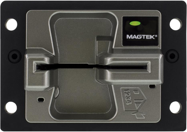
This document provides guidelines and technical information for designing solutions that integrate oDynamo, MagTek’s manual insertion Secure Card Reader Authenticator (SCRA) for OEM solutions.
oDynamo is a secure insertion card reader that is built to be durable and flexible. oDynamo allows for fast, reliable, and secure reading of magnetic stripe and chip card data from cards that meet the ISO 7810, 7811, and 7816 specifications. The slot and chassis are designed so cardholder-facing elements are impervious to liquid and other harsh environmental elements, making it an ideal solution for gas pumps, ATMs, and vending machines. Ultimate system design flexibility makes it ideal for a variety of unattended payment terminals.
oDynamo withstands a wide range of operational conditions and supports multiple communication protocols, and offers a USB connection, an Ethernet connection, and a serial connection.
oDynamo is made to work in harsh environmental conditions and delivers reliability of 500 thousand magnetic stripe swipes and 500 thousand chip inserts. The device is designed to be integrated into a solution that provides an enclosure. The device has been tested by an FCC lab for Class B radiated susceptibility and has no special shielding requirements.
oDynamo is secured by the MagneSafe™ Security Architecture (MSA), providing immediate encryption of card data using Triple DEA encryption with Derived Unique Key Per Transaction (DUKPT) key management. Additionally, oDynamo provides advanced MagnePrint® Card Authentication, which enables authorizing parties to detect and stop counterfeit card fraud in real-time. The firmware and the encryption keys are securely downloaded to the reader eliminating the chance of tampering.
The card latch feature allows the card to be securely held within the reader during the entire transaction process, and reduces the possibility of unwanted human intervention during card read operations. Power-fail card latch release and manual override features are available to ensure that a cardholder’s card can be easily retrieved under any conditions.
Cardholder-facing elements impervious to Liquid
Supports Multiple Protocols
Card Seated Sensor
ESD Protection: ±4kV contact discharge / ±8kV air discharge
In this document, oDynamo is referred to as the device. It is designed to be connected to a host, which is a piece of general-purpose electronic equipment which can send commands and data to, and receive data from, the device. Host types include PC computers/laptops, tablets, and smartphones. Generally, the host must have software installed that communicates with the device and is capable of processing transactions. The combination of device(s), host(s), software, firmware, configuration settings, physical mounting and environment, user experience, and documentation is referred to as the solution. During a transaction, the host and its software interact with the operator, such as a cashier or bank teller, while the device interacts with the cardholder.
A smooth deployment of a solution that integrates oDynamo requires some up-front planning and decision-making:
Determine the overall functional requirements and desired user experience of the solution oDynamo will be integrated into.
Determine what documentation and training will be required from solution design through testing and field deployment.
Determine what type of host oDynamo will connect to, and what connection type it will use. The host can be a computer with a USB port, serial (RS-232) port, or Ethernet port. When planning, include any additional support or devices required by the host and its connection, such as physical locations, mounting, and power connections.
From device delivery through assembly, shipping, installation, usage, and maintenance, the device must not be exposed to conditions outside the ratings in Appendix A Technical Specifications.
If the device is exposed to cold temperatures, adjust it to warmer temperatures gradually to avoid condensation, which can interfere with the operation of the device or cause permanent damage.
Upon receiving the device, inspect it according to D998200235 oDynamo Device Inspection procedure included in the box to make sure it originated from an authentic source and has not been tampered with.
Do not drop or shake the device.
The device should be transported/stored inside an anti-static bag at all times.
Before removing the device from the package, remove any static charge from your body by touching an earth-grounded metal surface.
Avoid touching the exposed pins on the connectors when handling the device.
For information about ongoing maintenance of the device, such as cleaning, see section 6 Maintenance.
EMVCo ESD Protection ±12kV air discharge
Card Latch
Anti-Tamper Security Features
Secure Download and Authentication of Firmware and of Encryption Keys
Determine what software will be installed on the host and how it will be configured. Software can include operating system, transaction processing software, security software, and so on. Include any additional support required by the software, such as network connections.
Determine how oDynamo should be configured, and specify that when you order devices. MagTek or your reseller can advise. For deep detail about configuration options and how they affect device behavior, see D998200162 ODYNAMO PROGRAMMER'S MANUAL (COMMANDS).
Determine how the solution design will integrate oDynamo electrically (see section 2 Electrical Integration for details).
Determine how the solution design will integrate oDynamo mechanically (see section 3 Mechanical Integration for details).
Develop an installation procedure. Basic device installation steps are provided in section 4 Installation, but installing technicians will need solution-specific materials. For example, technicians may be supported by incorporating a Maintenance Mode into the host software for configuration, updates, and diagnostic tests.
Determine how the solution will be tested and, if appropriate, how it will be certified.
Determine how the solution will be maintained. See section 6 Maintenance for guidance on maintaining the oDynamo portion of the solution.
Determine how the solution will be regularly inspected. MagTek provides D998200235 oDynamo Device Inspection with each device, but proper inspection will require additional solution-specific training, instructions, and visual references for inspecting the entire solution for tampering, unauthorized added components such as eavesdropping or skimming devices, and so on.
This document describes how to use oDynamo securely. Using the device in any way other than the approved methods described in this document invalidates the PCI PTS approval of the device.
Proper handling of the device throughout delivery, assembly, shipping, installation, usage, and maintenance is very important. Not following the guidelines in this document could damage the device, render it inoperable, and/or violate the conditions of the warranty.
The device does not contain any user-serviceable parts. Removing ANY screw, or otherwise attempting to disassemble or modify the device, is very likely to trigger tamper protection and render the device inoperable.


This document describes how to use oDynamo securely. Using the device in any way other than the approved methods described in this document invalidates the PCI PTS approval of the device.
Not following the guidelines in this section could damage the device, render it inoperable, and/or violate the conditions of the warranty.
This section provides information and guidelines for designing the mechanical aspects of a solution that incorporates oDynamo. MagTek strongly recommends vetting and testing solution designs before finalizing and deploying them, to make sure the design meets all requirements (e.g., functional, legal, security, certification, safety, and so on).
When designing the mechanical portions of a solution that incorporates oDynamo, consider the following:
Review section 1.6 About oDynamo Components for an overall introduction to the device’s physical features and what they are called.
Review Appendix A Technical Specifications.
See section 3.2 Dimensions for overall device dimensions.
Design the solution enclosure front panel. Information about fitting the device into a panel cutout are in section 3.4 Panel Cutout.
Determine how the device will be mounted. See section 3.5 Mounting for details. Coordinate with the electrical design team to make sure the panel design, mounting hardware, and solution-specific installation instructions meet electrical requirements.
Coordinate with the electrical design team to plan cable routing and fastening. See section 3.6 Cabling for details.
Consider additional factors that do not fit these categories. See section 3.7 Miscellaneous Considerations.
Review safe handling practices in section 1.9 Handling to make sure the logistical aspects of the solution design meet the device’s handling requirements.
Review recommended installation practices in section 4 Installation. The steps provided in that section depend on the solution design team to customize the steps or fill in solution-specific details before distribution to installation technicians.
Review section 6 Maintenance. When installed in the solution-specific enclosure, the maintenance procedures may require modifications, or the solution may require additional maintenance not covered in the general guidelines provided here.
Review any additional requirements from other agencies, such as PCI certification requirements, building codes, and so on, which may introduce additional constraints to the design.
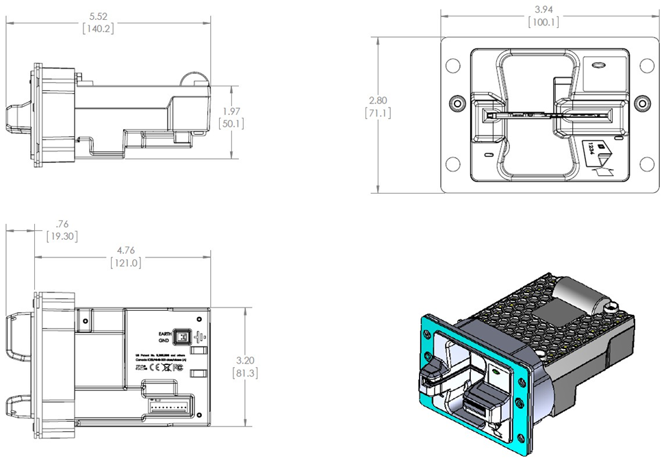
Overall dimensions of the device are shown in Figure 3-1. On request, MagTek can provide a 3D model of the device’s envelope to assist with the mechanical portion of solution design. MagTek strongly recommends building and testing prototypes with actual devices before finalizing the solution design.
Figure 3-1 - oDynamo Mechanical Dimensions in Inches [mm]
For optimum results, MagTek recommends orienting the device for horizontal card insertion (see Figure 3-2). Although it is possible to mount the device in vertical orientation, doing so may lead to impaired device function caused by the potential for increased accumulation of debris. Maintenance planning should take this into consideration.
Figure 3-2 - oDynamo Mounting Orientation
The device must be installed such that cardholders have a full, unobstructed view of the housing around the card insertion slot opening (“entry zone”) prior to insertion. This is to allow cardholders to easily detect suspicious objects in or around the card slot entry, such as bugs / skimmers / tapping mechanisms, and their wires or antennas. Installation height is one factor in meeting this requirement: Assuming the solution design does not add features that obstruct the view of the slot, choosing the installation height involves making sure the nominal inspection position has a view of the device that is no greater than 55° above the horizontal plane of the device (measured from the plastic body), which provides a view similar to Figure 3-3. If the solution mounts the device at a downward pitch, subtract the pitch angle from the 55° before calculating. For example, if the nominal inspection position is 12” away from the device and 60” above the ground, and the device is mounted at 0° pitch, the device’s slot must be mounted no higher than 60”-(12”)tan(55°-0°)=43”.
Figure 3-3 - View from 55 Degree Angle Above Device Horizontal
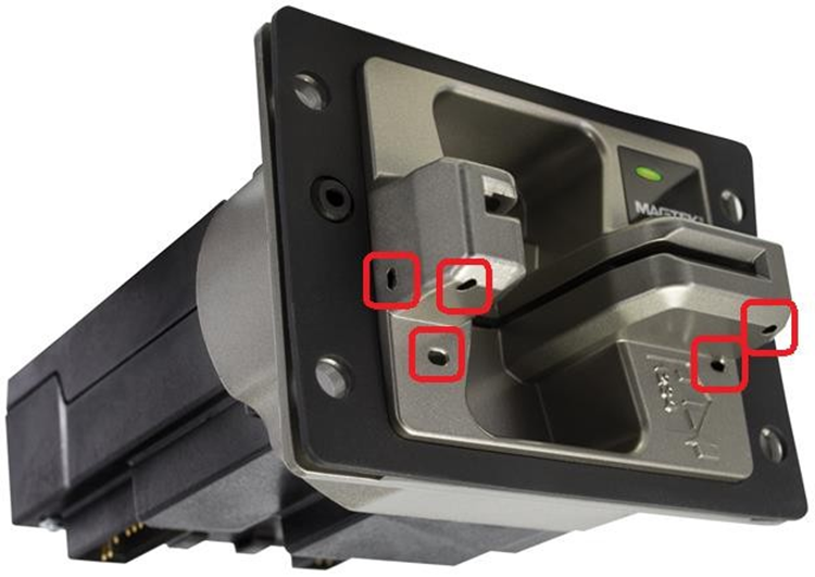
The device incorporates a number of drain holes, shown in Figure 3-4. Drainage requirements are as follows:
The drain holes must not be obstructed.
The device must be oriented with the drain holes on the bottom.
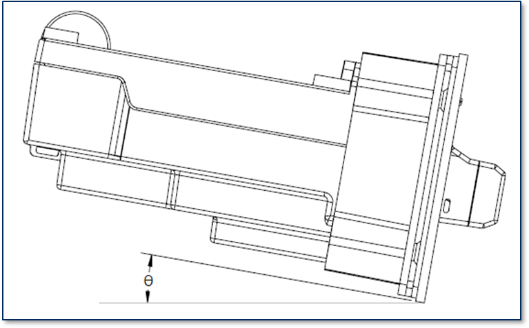
The enclosure must pitch the device’s face between 0 degrees (level) and 30 degrees downward. It must not pitch the device’s face upward (see Figure 3-5, 0° ≤ θ ≤ 30°).
Figure 3-4 - oDynamo Drain Holes
Figure 3-5 - oDynamo Mounting Pitch
The device is designed to be integrated into a solution design that includes an enclosure to secure the device and protect it from the elements. This section provides guidelines for creating a cutout in the enclosure’s front panel that accommodates the device.
The device’s installation face and gasket provide a seal against the elements:
The enclosure panel must be flat and rigid to produce a solid seal with the gasket and to provide security against tampering.
The solution’s enclosure must include a cutout that is sized to expose the device’s bezel while still squeezing the gasket.
The enclosure must protect the device from unauthorized tampering.
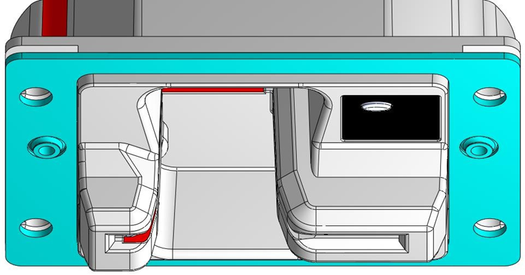
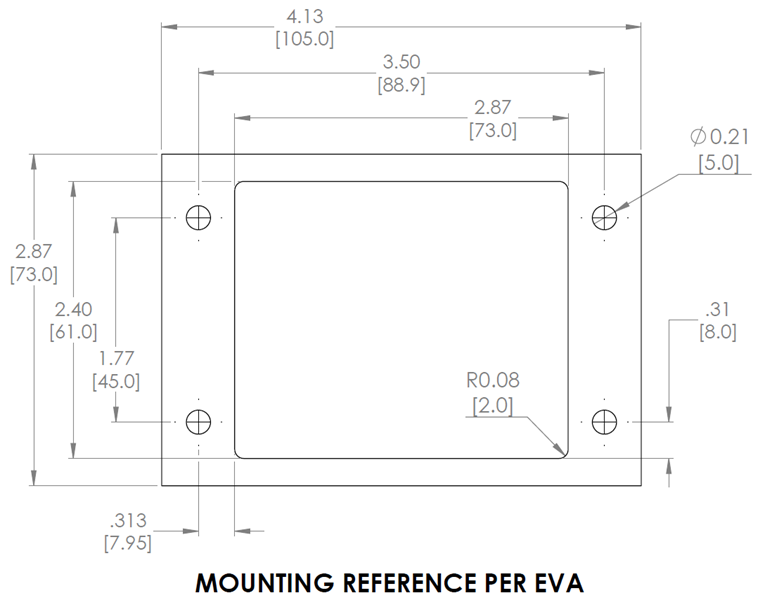
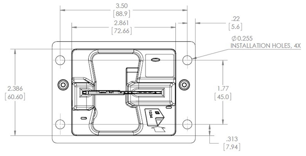
The device is sized for Compact Door Module hole patterns as specified by the European Vending Association (EVA) Electronic Payment Specification for Unattended Point Of Sale (UPOS), EVA EPS 1.1. Reference dimensions for the cutout in the solution enclosure, including the location of either screw holes or threaded studs, are shown in Figure 3-6; the outside dimensions of the sample cutout plate represent absolute minimum required clearances for the cutout’s overall placement in the enclosure. Detailed dimensions of the device’s installation face are shown in Figure 3-7.
Figure 3-6 - oDynamo Panel Cutout Dimensions in Inches [mm]
Figure 3-7 - oDynamo Mounting Face Dimensions in Inches [mm]
The solution design’s mounting hardware and torque specifications must apply adequate force to create a water-tight seal between the enclosure and the gasket. For example, for M4 nuts/bolts, the torque may be in the range of 0.7 N-m (6 to 7 in-lbs.).
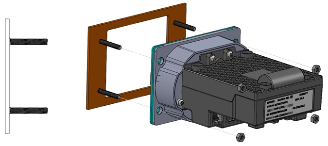
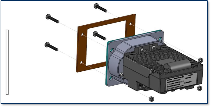
The device is designed to be mounted either onto screws (see Figure 3-9) or onto threaded studs permanently attached to the enclosure (see Figure 3-8), and nuts. The maximum shaft size for screws or studs is #10 or M5. Make sure mounting hardware in contact with the mounting holes conforms to the grounding requirements in section 2 Electrical Integration.
Figure 3-8 - oDynamo Threaded Stud / Nut Mounting
Figure 3-9 - oDynamo Screw/Nut Mounting
This section provides information about mechanical integration of cables into a solution design. For details about electrical aspects of integrating the device, see section 2 Electrical Integration.
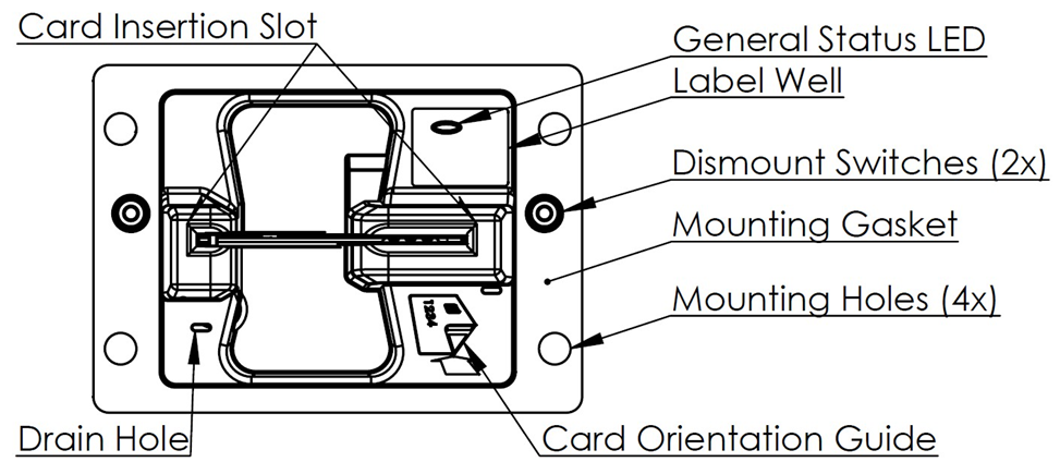
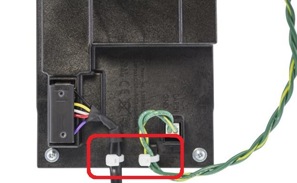
The device incorporates cable tie mounts (see Figure 1-1) that can be used with cable ties (not included) to implement cable strain relief. See Figure 3-10 for an example of tying down cables.
Figure 3-10 - Cable Strain Relief
The enclosure should include adequate clearance for installation and maintenance personnel to connect and disconnect all cables. If the solution uses the device’s cable tie mounts for strain relief, it should provide additional clearance to remove and re-fasten the cable ties. It should also provide support for the device when cables are being connected and disconnected.
Installation technicians will need to be provided detailed instructions for installing the cabling. For some basic guidelines, see section 4 Installation.
The device includes a label well (see Figure 1-1) around the General Status LED that can accommodate solution-branded labels. Labels should incorporate a cutout so they do not obstruct the LED.
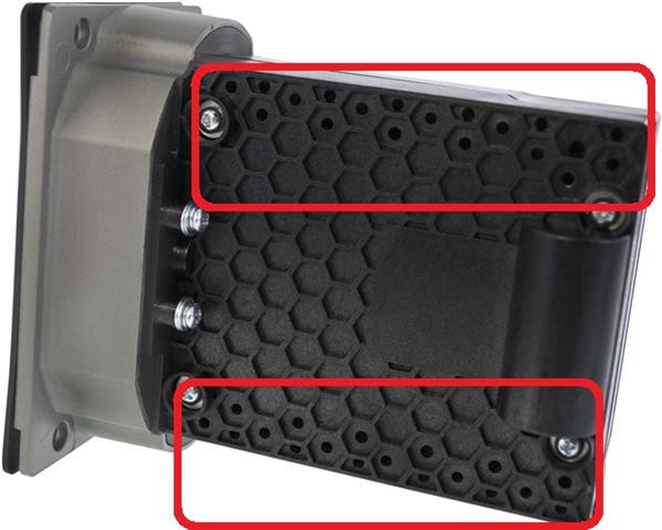
The device operates on low power, so no special cooling should be necessary. However, there must be adequate clearance around the vent holes in the top of the device’s body for heat to escape (see Figure 3-11), and the enclosure must not be an isolated thermal system that traps indefinite amounts of heat.
This document describes how to use oDynamo safely and securely. Using the device in any way other than the approved methods described in this document invalidates the PCI PTS approval of the device.
Not following the guidelines in this section could damage the device, render it inoperable, and/or violate the conditions of the warranty.
This section provides information and guidelines for designing the electrical aspects of a solution that incorporates oDynamo. MagTek strongly recommends vetting and testing solution designs before finalizing and deploying them, to make sure the design meets all requirements (e.g., functional, legal, security, certification, safety, and so on).
When designing the electrical portions of a solution that incorporates oDynamo, consider the following:
Review section 1.6 About oDynamo Components for an overall introduction to the device’s physical features and what they are called.
Review Appendix A Technical Specifications.
See all the subsections below for options and constraints involving cable design, signals, power, and other aspects of electrical integration. To coordinate with the solution’s mechanical design team about cables, see section 3.6 Cabling.
Consider additional factors that may affect the electrical aspects of the solution design. See section
Review safe handling practices in section 1.9 Handling to make sure the logistical aspects of the solution design meet the device’s handling requirements.
Review recommended installation practices in section 4 Installation. The steps provided in that section depend on the solution design team to customize the steps or fill in solution-specific details before distribution to installation technicians.
Review section 6 Maintenance. When installed in the solution-specific enclosure, the maintenance procedures may require modifications, or the solution may require additional maintenance not covered in the general guidelines provided here.
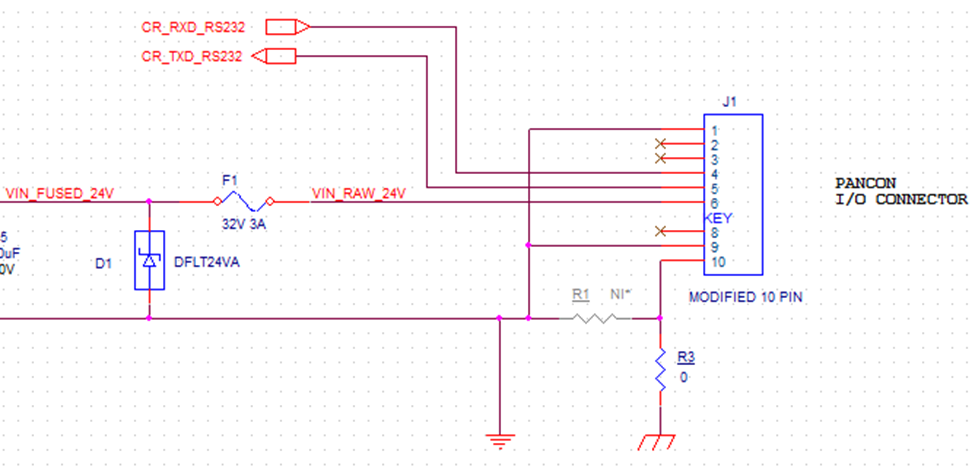
To guard against ground loops and to protect the device against electrostatic discharge (ESD), it is important that solution designs ground the device correctly. MagTek strongly recommends checking whether the host’s communication ports provide earth ground, and whether the cables carry that ground all the way to the corresponding ports on the device’s board. This will help make an informed decision about proper grounding. There are three paths to provide earth ground to the device; MagTek recommends all solution designs bring in earth ground to the device using one and only one of the possible paths:
Bring in earth ground through pin 10 of the RS-232 and Power Port [J1]
Bring in earth ground through pin 1 and pin 2 of the Alternative Earth Grounding Port [J9]
Bring in earth ground from the host through the USB cable’s metal connector shell to the USB Device Port [J3]
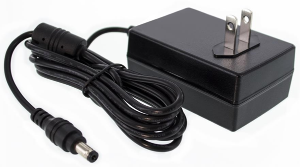
If it is not practical to connect earth ground using only one of the available paths (for example, if the solution uses multiple shielded cables that provide earth ground from the host), then the solution design must ensure that every source of external earth ground is at the same electrical potential, to prevent damaging ground loop currents from occurring. MagTek also recommends using an earth ground isolated power supply (i.e., with the power supply’s negative output not connected to earth ground) like the one shown in Figure 2-1, because a non-isolated supply would connect digital ground to earth ground, defeating the separation of digital ground from earth ground on the device’s PCBs.
Figure 2-1 - Example Earth Ground Isolated 24V Regulated Power Supply
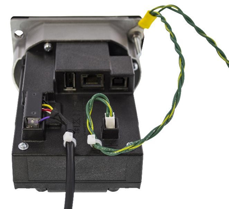
In addition, solutions that incorporate devices with a metal bezel must ground the bezel to the same earth ground potential as the point chosen above. This provides an additional path to protect the device from electrostatic discharge during card insertion and provides additional protection for the device’s electronics. MagTek recommends this earth grounding cable comprise two 18AWG stranded wires twisted together to form a Y cable. Figure 2-2 shows a prototype example of a Y cable that could be included in a standard installation kit.
MagTek recommends using shielded cables to provide noise immunity and to prevent radiated emissions. The device itself has been tested by an FCC lab for Class B radiated susceptibility and has no special shielding requirements. For details, see the FCC information provided at the beginning of this document.
MagTek also recommends that all communication cabling (i.e., USB, Ethernet, RS-232) should be draped together where possible, and isolated from the earth grounding cable to oDynamo and any other unrelated wiring at the installation site that could potentially couple noise into the device and degrade the low-level MagnePrint head signals.
The device has no special requirements for power conditioning or signal conditioning.
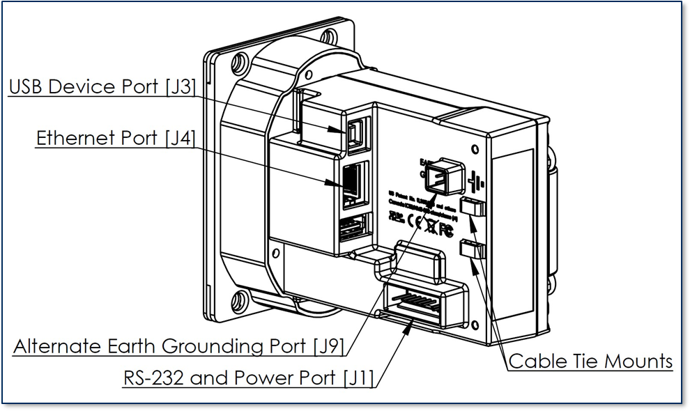
oDynamo provides the following connections (see Figure 1-1 - oDynamo Major Components):
·An RS-232 and Power port, which must be connected to a power source and may be connected to an RS-232 host for bidirectional communication. For details, see section 2.5 RS-232 and Power Port.
A USB Device port, which can be connected to a USB-capable host for bidirectional communication. For details, see section 2.6 USB Device Port [J3].
An Ethernet port, which can be connected to an Ethernet-capable host for bidirectional communication. For details, see section 2.7 Ethernet Port [J4].
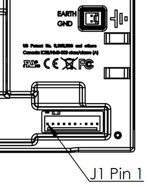
The RS-232 and Power port must be connected to a power source and may be connected to an RS-232 host for bidirectional communication. It is a Pancon MTSS100-10-CB header designed to mate with a Pancon MAS-CON CE100F22-10-CB connector or equivalent. Pinouts and a schematic excerpt are shown in Figure 2-3 and Table 2-1. Pin 1 is located nearest the front bezel, as shown in Figure 2-4.
Figure 2-3 - oDynamo RS-232 and Power Port J1
Figure 2-4 - oDynamo J1 Pin 1 Location
The Vin and Digital Ground (SG) pins must be connected across the terminals of a power supply. Vin is protected by an internal (non-serviceable) 3A fuse, shown in Figure 2-3.
oDynamo should be powered by a regulated isolated power supply having a fixed output between 9VDC
±5% to 24VDC ±5%, with worst-case output ripple voltage not exceeding 100mV RMS. See section 2.2 Grounding / ESD Protection for additional important information about sourcing an appropriate power supply. For optimal performance, solutions using less than 24VDC must configure the device to disable the card latch, because below 24V the latch behavior is not reliable.
The maximum current draw required from the power supply depends on the selected power supply voltage and the device features used in the solution design. To calculate the maximum required current, use the information in Table 2-2. For example, using a 24V power supply, with card latch function enabled, the maximum total current draw is 417 mA + 170 mA = 587 mA @ 24V.
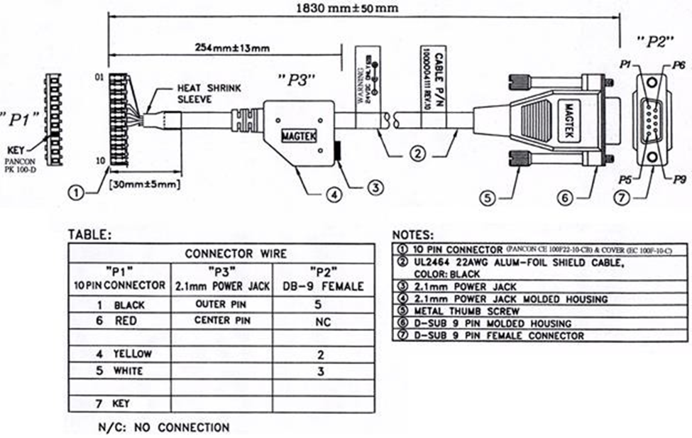
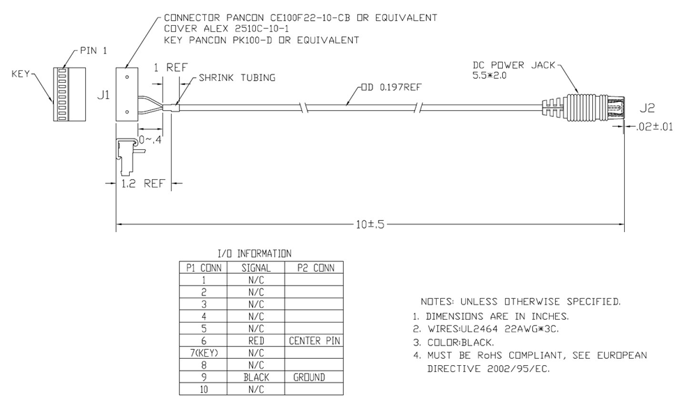
MagTek recommends 22AWG wires for all signal and power lines. The connector contacts must have a minimum of 15µ" of selective gold plating over nickel. MagTek also recommends filling the pin 7 hole on the cable connector with a Pancon PK100-D polarizing key or equivalent to guarantee the cable will mate with the device in the correct position and orientation.
For oDynamo solutions that use the RS-232 interface, MagTek recommends enclosing all wires in a shielded earth-grounded jacket, and a maximum length for the combination RS-232/power cable of 6 feet. See Figure 2-5 for an example of this RS-232 / Power cable, part number 1000004111.
For oDynamo solutions that do not use RS-232 communication, oDynamo can be powered using a simple power cable using 22AWG wires. See Figure 2-6 for an example power cable, part number 1000003906.
Programmers should see section 8 Developing Host Software for cross-references to programming tools and documentation for communicating through the port and configuring the device.
The factory default communication settings for the RS-232 port are shown in Table 2-3. The host must begin communication with those settings, then can use that connection (or the USB port) to reconfigure the port and switch to the new settings. Programmers should see section 8 Developing Host Software for cross-references to programming tools and documentation for communicating through the port and configuring the device.
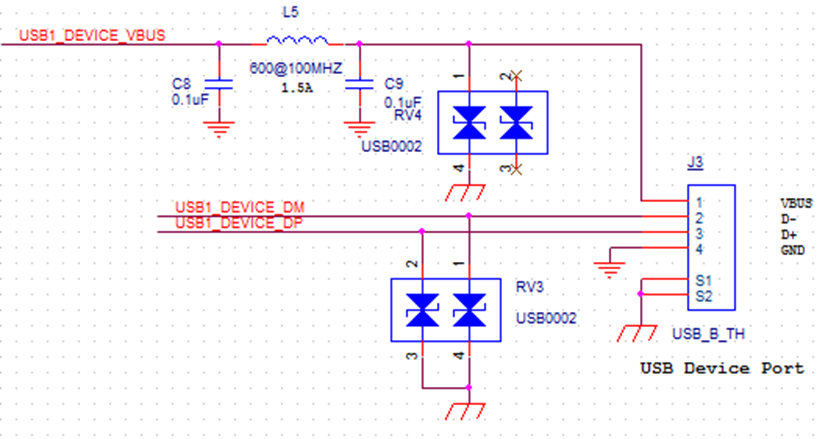
The USB Device port J3 can be used to provide bidirectional communication with a USB-capable host. It is a USB 2.0 Type B receptacle designed to mate with a standard USB Type B connector found on the peripheral end of commercially available USB peripheral cables. Pinouts and a schematic excerpt are shown in Figure 2-7.
Figure 2-7 - Pinouts for oDynamo USB Device Port J3
Because the device relies exclusively on RS-232 and Power Port [J1] for power, it draws negligible current from the USB Device Port.
Programmers should see section 8 Developing Host Software for cross-references to programming tools and documentation for communicating through the port.
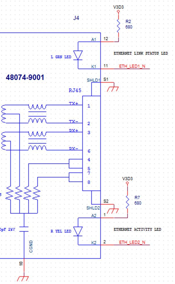
The Ethernet Port can be used to provide bidirectional communication with an Ethernet-capable host. It is an RJ45 receptacle designed to mate with a standard RJ45 connector found on commercially available Ethernet cables. Pinouts and a schematic excerpt are shown in Figure 2-7.
Figure 2-8 - Pinouts for oDynamo Ethernet Port J4
The RJ45 connector contains integrated magnetics, and supports standard 10/100 speeds. The green LED on the port provides Ethernet Link Status, and the amber LED shows Ethernet Activity.
MagTek recommends using CAT5 cables for the Ethernet connection: Connecting the device to an Ethernet switch or router requires a “straight” Ethernet cable; connecting the device directly to a host’s Ethernet port requires a crossover Ethernet cable.
The Alternative Earth Grounding port J9 can be used in solutions that need a connection for attaching external earth ground (see section 2.2 Grounding / ESD Protection). It is a 2-pin TE Connectivity 3-641126-2 header, compatible with a Pancon MAS-CON CE100F22-2-CB connector or equivalent. If the solution uses J9 , both pins should be connected directly to earth ground.
If the solution design calls for custom cables, use 22 AWG wire or thicker. The contact must have a minimum of 15µ" of selective gold plating over nickel.

Review any additional requirements from other agencies, such as PCI certification requirements, building codes, and so on, which may introduce additional constraints to the solution design.
An Alternative Earth Grounding port, which can be used in solutions that need a connection for attaching external earth ground. For details, see section 2.2 Grounding / ESD Protection and section 2.8 Alternative Earth Grounding Port [J9].
TXD (To host)
4
RXD (From host)
5
Vin
6
Polarizing Key
7 (no pin present)
Float
8
Digital Ground (SG)
9
Optional Earth Ground (see section 2.2)
10
=
Maximum current draw
12V ±5%
Do not use card latch
+
338 mA
=
Maximum current draw
9V ±5%
Do not use card latch
+
433 mA
=
Maximum current draw
1) Card latch solenoid is energized for 0.5 seconds.
Start bit
1 bit
Data Length
8 bits (Bit 7: MSB, Bit 0: LSB)
Parity
No Parity
Stop bit
1 bit
Transmission Speed (Baud rate)
9600 Baud
RS-232 Signal
Connector Pin
Digital Ground (SG)
1
Float
2
Float
3
Power Supply Voltage
Card Latch Enabled?
Maximum Steady State Current
Total
24V ±5%
No: 0 mA
Yes: 417 mA1
+
Parameter
Specification
Transmission Protocol
Asynchronous
Communication Method
Half Duplex
Flow Control
None

170 mA