Loading...
Loading...
Loading...
Loading...
Loading...
Loading...
Loading...
Loading...
Loading...
Loading...
Loading...
Loading...
Loading...
Loading...
Loading...
Loading...
Loading...
Loading...
Loading...
Loading...
Loading...
Loading...
Loading...
Loading...
Loading...
Loading...
Loading...
Loading...
Loading...
Loading...
Loading...
Loading...
Loading...
Loading...
Loading...
Loading...
Loading...
Loading...
Loading...
Loading...
Loading...
Loading...
Loading...
Loading...
Loading...
Loading...
Loading...
Loading...
Loading...
Loading...
Loading...
Loading...
Loading...
Loading...
Loading...
Loading...
Loading...
Loading...
Loading...
Loading...
Loading...
Loading...
Loading...
Loading...
Loading...
Loading...
Loading...
Loading...
Loading...
Loading...
Loading...
Loading...
Loading...
Loading...
Loading...
Loading...
Loading...
Loading...
Loading...
Loading...
Loading...
Loading...
Loading...
Loading...
Loading...
Loading...
Loading...
Loading...
Loading...
Loading...
Reserved
This page provides comprehensive programmer's manuals, EMV flowcharts, configuration instructions, and demo guides to help you integrate the oDynamo hybrid insertion secure card reader authenticator into your software solutions using direct commands or MagTek's Common Message Structure (MTCMS) across multiple development platforms.
Reference Section
Information Available
A reference manual providing the direct command set for controlling the oDynamo's magnetic stripe and EMV contact chip reading functions in unattended terminal applications.
A programmer's reference document that provides EMV transaction flow instructions for software developers creating solutions that include a MagTek Secure Card Reader Authenticator (SCRA) device connected to Windows, Android, or iOS.
A guide describing how to use the MagTek EMV Configuration application to verify EMV configurations, tags, and Certificate Authority Public Keys (CAPKs) on an oDynamo connected to a host PC via USB.
A programmer's reference manual for developers creating Windows and cross-platform software solutions that include a MagTek Common Message Structure (MTCMS) device.
A reference manual providing instructions for software developers who want to create Windows C++ software solutions that communicate with a MagTek Common Message Structure (MTCMS) device.
This document provides the instructions on how to use the MTCMSNET Demo.
Need Help?
For additional support, please contact MagTek Support:
Technical Support:
📧 Email: support@magtek.com
📞 Phone: 1-562-546-6800 (US)
🕐 Hours: Monday-Friday, 5:30 AM - 5:00 PM PST
Online Resources:
🌐 Support Portal: developer.magtek.com
Documentation Feedback:
Help us improve this documentation!
This page provides documentation for MagTek OEM magnetic stripe and EMV insertion readers and components, including developer guides, mechanical drawings, firmware downloads, and setup instructions to help integrate secure card reading into your own kiosk, payment terminal, and unattended hardware designs.
A small‑form‑factor device that combines a 3‑track magnetic stripe secure card reader authenticator with contact EMV chip reading, and can be paired with DynaWave to add contactless/NFC capabilities, offering a flexible hybrid solution.
The IP34-rated mDynamo with Outdoor Bezel is a compact EMV chip card reading module built on the MagneSafe security architecture, featuring a spring‑loaded door to block dust and moisture for reliable integration into both indoor and outdoor unattended kiosks.
A manually operated, push‑in magnetic stripe reader that minimizes incorrect card insertion with an optional dual‑head design and an open‑frame construction that keeps the card slot free of debris, available in TTL, RS‑232, and USB interfaces.
oDynamo is a PCI PTS 5.x SRED‑certified, secure insertion card reader authenticator for OEM solutions that reads both magnetic stripe and EMV contact chip data, supports USB, Ethernet, and RS‑232 connections, and features a sealed, liquid‑impervious chassis designed for harsh unattended environments like gas pumps, ATMs, and vending machines.
Secure card reader authenticator that reads up to three tracks from ISO and AAMVA cards, featuring a sealed, tamper‑resistant design for unattended and outdoor installations.
Secure card reader authenticator that reads up to three tracks from ISO and AAMVA cards, featuring a sealed, tamper‑resistant design for unattended and outdoor installations.
OEM Components
The first magnetic sensing, media-validating, tamper-resistant security module that reads three tracks of magnetic stripe data, encrypts it inside the head using 3DES and DUKPT, and authenticates cards with MagnePrint technology to help OEMs meet stringent PCI security requirements.
High-performance, low-cost three-channel magnetic stripe decoder chips that significantly simplify the card-reader-to-micro-controller interface, including the Delta ASIC (proven for three-track reading) and the next-generation Qwantum ASIC with integrated encryption, SPI support, and ultra-low power modes.
An EMV contact chip card reader module that connects via USB, features two optional auxiliary ports (SPI and UART) to easily add magnetic stripe or contactless/NFC reading, and is built on the MagneSafe Security Architecture for secure chip card transactions.
A compact bidirectional magnetic stripe swipe reader available in USB keyboard emulation or HID format, designed for low‑cost, high‑reliability card reading in payment, membership, loyalty, and identification applications.
Highly efficient three-channel fully integrated magnetic stripe decoder chips (including the Delta and Qwantum families) that simplify the card-reader-to-micro-controller interface via MagTek's "Shift-Out" protocol while supporting advanced features like integrated encryption, SPI, and USB-C connectivity.
Modular card guide rails that work with MagTek’s IntelliHead product line (including the encrypted MagneSafe™ IntelliHead) to provide a complete card swipe assembly in lengths such as 43mm, 60mm, 70mm, and 90mm for various OEM integration needs.
A low-profile magnetic read head with an embedded high-performance multi-channel decoder chip that outputs raw track data using the simple "Shift-Out" protocol (data/strobe), making it ideal for battery-powered or microcontrollers where minimal power consumption is critical.
Product
Description
OEM Readers
Need Help?
For additional support, please contact MagTek Support:
Technical Support:
📧 Email:
📞 Phone: 1-562-546-6800 (US)
🕐 Hours: Monday-Friday, 5:30 AM - 5:00 PM PST
Online Resources:
🌐 Support Portal: developer.magtek.com
Documentation Feedback:
Help us improve this documentation!
📞 Phone: 1-562-546-6800 (US)
🕐 Hours: Monday-Friday, 5:30 AM - 5:00 PM PST
Online Resources:
🌐 Support Portal: developer.magtek.com
Documentation Feedback:
Help us improve this documentation!
This class allows building MagTek CMS messages to be used in communications with MagTek CMS devices.
This constructor method builds an MTCMSMessage instance with the provided values.
public void MTCMSMessage(int messageType, int applicationID, int commandID, int dataTag, byte[] data)Parameters:
Parameter
Description
messageType
Return Value: None
This constructor method builds an MTCMSMessage instance with the provided byte array value.
Parameters:
Return Value: None
This method sets the value of MessageType.
Parameters:
Return Value: None
This method sets the value of ApplciationID.
Parameters:
Return Value: None
This method sets the value of CommandID.
Parameters:
Return Value: None
This method sets the value of ResultCode.
Parameters:
Return Value: None
This method sets the value of Data Tag and the value of Data.
Parameters:
Return Value: None
This method returns the value of MessageType.
Return Value: MessageType value.
This method returns the value of ApplicationID.
Return Value: ApplicationID value.
This method returns the value of CommandID.
Return Value: CommandID value.
This method returns the value of ResultCode.
Return Value: ResultCode value.
This method returns the value of Data Tag.
Return Value: Data Tag value.
This method returns the value of Data.
Return Value: Data value.
This method returns the message bytes.
Return Value: Message bytes.
After creating an instance of the MTCMS class in your software project, use the methods described in this section to communicate with MagTek CMS device.
This method initiates request to discover devices that are visible to the host using the specified connection interface. The DeviceListReceived event will provide information regarding the available devices once the discovery process is completed.
Parameters:
MessageType value
applicationID
ApplicationID value
commandID
CommandID value
dataTag
Data Tag value
data
Data value
Parameter
Description
messageBytes
Message byte array value
Parameter
Description
messageType
MessageType value
Parameter
Description
applicationID
ApplicationID value
Parameter
Description
commandID
CommandID value
Parameter
Description
resultCode
ResultCode value
Parameter
Description
dataTag
Data Tag value
data
Data value
public void MTCMSMessage(byte[] messageBytes)public void setMessageType(int messageType)public void setMessageType(int messageType)public void setCommandID(int commandID)public void setResultCode (int resultCode)public void setData (int dataTag, byte[] data)public int getMessageType()public int getApplciationID()public int getCommandID()public int getResultCode()public int getDataTag()public byte[] getData()public byte[] getMessageBytes()MTConnectionType value: MTConnectionType.USB, MTConnectionType.IP, MTConnectionType.Serial
Return Value: None
This method sets the connection type of the device..
Parameters
Parameter
Description
connectionType
MTConnectionType value: MTConnectionType.USB, MTConnectionType.IP, MTConnectionType.Serial
Return Value: None
This method sets the address of the device.
Parameters:
Parameter
Description
deviceAddress
String value of the address.
The following table shows the address formats supported by the different connection types:
Connection Type
Address Format Parameter
Address Format Description
USB
[PATH]
The OS specific device path to the USB device. The path is normally retrieved from the Address property of MTDeviceInformation.
IP
[IPA]
Connection Type
Address Format
Serial
PORT=[PORT],
BAUDRATE=[BAUDRATE],
DATABITS=[DATABITS],
PARITY=[PARITY],
STOPBITS=[STOPBITS],
HANDSHAKE=[HANDSHAKE],
STARTINGBYTE=[STARTINGBYTE],
ENDINGBYTE=[ENDINGBYTE],
CRCMODE=[CRCMODE]
Connection Type
Parameter
Description
Serial
[PORT]
The OS specific device path to the serial port (i.e. COM4).
Serial
[BAUDRATE]
Return Value: None
This method sets the device ID.
Parameter
Description
deviceID
String value of the device ID.
Return Value: None
This method opens the connection to the device.
Parameters: None
Return Value: None
This method closes the connection to the device.
Parameters: None Return Value: None
This method returns whether the device is connected or not.
Parameters: None
Return Value:
Return true if the device is connected. Otherwise, return false.
This method sends a command string to the device.
Parameters:
Parameter
Description
dataString
Command to be sent in hexadecimal string format.
Return Value:
0 = Success
9 = Error
15 = Busy
This method sends a command to the device.
Parameters:
Parameter
Description
dataBytes
Command to be sent in byte array format.
dataBytesLength
Length of the command bytes.
Return Value:
0 = Success
9 = Error
15 = Busy
This method sends a command to the device.
Parameters:
Parameter
Description
message
MTCMSMessage to be sent to the device.
Return Value:
0 = Success
9 = Error
15 = Busy
MTCMS_API void requestDeviceList(MTConnectionType connectionType); Parameters:Parameter
Description
connectionType
MTCMS_API void setConnectionType(MTConnectionType connectionType); MTCMS_API void setAddress(const char* deviceAddress);MTCMS_API void setDeviceID(const char* deviceID); MTCMS_API void openDevice(); MTCMS_API void closeDevice();MTCMS_API bool isDeviceConnected();MTCMS_API int sendCommandString(const char* dataString);MTCMS_API int sendDataBytes(
const unsigned char* dataBytes,
int dataBytesLength);MTCMS_API int sendMTCMSMessage(MTCMSMessage* message);The IP address of the device in dotted-quad notation (i.e. 192.178.1.123).
IP
[PORT]
The TCP port of the device. (Default: 5000)
The data baud rate . (Default: 9600)
Serial
[DATABITS]
The data bits per byte. (Default: 8)
Serial
[PARITY]
The parity checking protocol. (Default: NONE).
Supported Values: NONE,EVEN,ODD,SPACE,MARK
Serial
[STOPBITS]
The number of stop bits per byte. (Default: 1)
Supported Values: 1,1.5,2
Serial
[HANDSHAKE]
The handshaking protocol for serial port transmission of data. (Default: NONE)
Supported Values: NONE,RTS,XONXOFF,RTSXONSOFF
Serial
[STARTINGBYTE]
The special character used as the starting byte for each message. (Default is empty string)
An empty string indicates no special character is used as the starting byte for each message.
Serial
[ENDINGBYTE]
The special character used as the ending byte for each message. (Default is 0x0A)
Serial
An empty string indicates no special character is used as the ending byte for each message.
Serial
[CRCMODE]
A value of 0 indicates CRC is disabled, otherwise CRC is enabled. (Default: 0)
This document describes the master set of messages a host can send and receive via byte-by-byte direct communication with secure card reader authenticator devices that implement MagTek Common Message Format (MCMF), such as oDynamo (referred to in this document as “the device”).
The general terms “device” and “host” are used in different, often incompatible ways in a multitude of specifications and contexts. For example, “host” may have different a meaning in the context of USB communication than in the context of networked financial transaction processing. In this document, “device” and “host” are used strictly as follows:
Device refers to the MagTek product that receives and responds to the command set specified in this document. Devices include oDynamo.
Host refers to the piece of general-purpose electronic equipment the device is connected or paired to, which can send data to and receive data from the device. Host types include PC and Mac computers/laptops, tablets, smartphones, teletype terminals, and even test harnesses. In many cases the host may have custom software installed on it that communicates with the device. When “host” must be used differently, it is qualified as something specific, such as “acquirer host” or “USB host.”
Similarly, the word “user” is used in different ways in different contexts. This document separates users
into more descriptive categories:
The cardholder
The operator (such as a cashier, bank teller, customer service representative, or server), and The developer or the administrator (such as an integrator configuring the device for the first time).
Because some connection types, payment brands, and other vocabulary name spaces (notably Bluetooth, EMV, smart phones, and more recent versions of Windows) use very specific meanings for the term “Application,” this document favors the term software to refer to software on the host that provides a user interface for the operator.
The word terminal uses the EMV definition, which may mean a stationary interface for a cashier or teller at a point of sale or bank, an ATM or other unattended device, a handheld service interface on an air or water craft, and so on. In some situations the terminal interacts with the operator, though in self-service situations the terminal might interact with a cardholder directly.
The combination of device(s), host(s), software, firmware, configuration settings, physical mounting and environment, user experience, and documentation is referred to as the solution.
This device and related products use a common communication protocol across a variety of physical connection layers, which can include universal serial bus (USB), Ethernet, RS-232, and Bluetooth Low Energy (“Bluetooth LE”). The set of available connection layers depends on the device. Details for communicating with devices via each physical connection type are provided in section 3 Connection Types.
The information in this document applies to multiple devices. When developing solutions that use a specific device or set of devices, integrators must be aware of each device’s communication interfaces, features, and configuration options, which affect the availability and behavior of some messages. Table 1-1 provides a list of device features that may impact message availability and behavior.
MagTek provides convenient Software Development Kits (SDKs) that include libraries for some connection types and development frameworks. These SDKs wrap the details of the connection in an interface that conceptually parallels the device’s internal operation, freeing developers from dealing with the details of the connection, and allowing them to focus on software business logic. In cases where SDK libraries are available, developers also have the option to revert to direct communication with the device using libraries available in the chosen development framework. This document provides information and support for the latter method. Information about using MagTek SDKs is available in separate documentation.
Signature Capture (“SC”)
No
Custom messages
No
Bitmaps
No
Clear text user data
No
Capacitive Keypad (“Cap Keypad”)
No
Power management
No
PCI 4.x Key Block
Yes
IntelliHead
No
Max financial card PAN length
19
MagneSafe 2.0 (MS 2.0)
No
Communication Interfaces
USB Connection to peripherals
No
USB Connection to host
Yes
TCP/IP over 802.11 wireless connection
No
Ethernet connection
Yes
Apple 30-pin connection
No
RS-232 connection
Yes
Bluetooth LE connection
No
EMV Features
Chip card contact
Yes
Chip card L1 mode
No
Chip card L2 mode
Yes
RID CAPK Key Slots
Yes
Multiple payment brand defaults
Yes
PayPass support
No
payWave support
No
Expresspay support
No
D-PAS support
No
Configurable EMV Support
No
Feature
oDynamo
Reserved
Reserved
Reserved
Reserved
Reserved
General Features
Feature
oDynamo
Reserved
Reserved
Reserved
Reserved
Reserved
Chip card contactless
No
Details about the tag set in this section are provided in EMV Integrated Circuit Card Specifications for Payment Systems v4.3, Book 3, Annex A. In addition, MagTek defines custom tags for use with the device, which are clearly identifiable as beginning with DFDF. The information here applies to the newest firmware with the EMV 4.3J kernel. For older firmware, please see previously published revisions of this manual. When upgrading from firmware that uses an older EMV kernel, please note the following changes to EMV configuration files:
Tags removed from Contact Terminal Settings
DFDF5B Terminal Capabilities for Purchase Transaction
DFDF5C Terminal Capabilities for Cashback Transaction
DFDF75 Terminal Capabilities for Inquiry Transaction
DFDF76 Terminal Capabilities for Transfer Transaction
DFDF6E Terminal Capabilities for Payment Transaction
DFDF7E Terminal Capabilities for Cash Advance
DFDF7F Terminal Capabilities for Cash Manual
Tag added to Contact Terminal Settings
DF812D Display hold time (n*100ms, default=10=1 second)
Pauses transaction for the following EMV messages
Tags moved from Contact Terminal Settings to each slot of Contact Application Settings
9F15 Merchant Cat Code
9F16 Merchant ID
Certificate Authority Public Key (CAPK) slots are left blank, there are 52 CAPK slots.
EMV Contact Terminal Settings and Defaults
This section lists the default EMV Contact Terminal default settings. For information about reading and changing these settings, see Application Group 0x07 - EMV L2 Contact Messages (Chip Card L2 Mode Only).
EMV Contact Application Settings and Defaults (Contact Only)
Invalid PIN length
INCORRECT PIN
PIN OK
NOT ACCEPTED
9F4E Merchant Name and Location
5F36
02
1
MagTek
Transaction Currency Exponent
5F57
00
1
MagTek
Account Type
9F1A
08 40
2
MagTek
Terminal Country Code
9F1D
31 31 32 32 33 33 34
34
8
MagTek
Terminal Risk Management Data
9F1E
8
9F33
20 48 00
3
Manufacturer
Terminal Capabilities
9F35
24
1
Manufacturer
Terminal Type
9F3A
00 00 00 00
4
MagTek
Amount Reference Currency
9F3C
09 98
2
MagTek
Transaction Reference Currency Code
9F3D
02
1
MagTek
Transaction Reference Currency Exponent
9F40
72 00 00 F0 01
5
Manufacturer
Additional Terminal Capabilities
DF812D
00 00 0A
3
MagTek
Message Pause Time (100msec)
DFDF01
A0 00 00 00 04 F8 00
10 00
16
MagTek
Certificate Revocation List. Contains zero or more sequences of:
· 5 byte Registered Application Provider ID (RID)
· 1 byte CAPK Index
· 3 byte Certificate Serial Number
DFDF05
9A 82 9F 36 9F 1E 9F
10 9F 5B 9F 33 9F 35
95 9F 01 5F 24 5A 5F
34 8A 9F 15 9F 16 9F
39 9F 1A 9F 1C 57 9F
02 5F 2A 9F 21 9C
128
MagTek
Reversal message for EMV transaction. Data Object List (DOL) of tags to be included in Batch Data for EMV Transactions.
DFDF06
8A 91
2
MagTek
Data Object List (DOL) of tags to be checked in EMV Online Response in EMV Transactions.
DFDF14
00 00 75 30
4
MagTek
Socket timeout for Online Processing (in ms)
DFDF15
00 00 00 01
4
MagTek
Number of connection retries in Online Processing
DFDF16
00 00 00 80
4
Read Only
Maximum length of issuer script
DFDF17
9A DF DF 28 9F 02
9F 03 5A 89 9F 10 9F
15 9F 16 9F 4E 82 8E
5F 24 5F 25 9F 06 9F
07 9F 0D 9F 0E 9F 0F
9F 26 9F 27 9C 9F 33
9F 34 9F 35 9F 36 9F
37 9F 39 9F 40 9F 41
9F 53 95 9B 9F 5B DF DF 00 9F 1E 9F 1A 5F 2A 9F 01 8A DF 81 20
128
MagTek
Batch Message for EMV Transaction Data Object List (DOL) of tags to be included in Batch Data for EMV Transactions
DFDF21
20
1
Compile Only
Number of supported AIDs
DFDF26
4D 41 47 54 45 4B 20
44 45 46 41 55 4C 54
16
MagTek
EMV Database Label
DFDF4E
00 00 01 10
4
MagTek
Transaction Reference Currency Conversion. See the function definition of the same name in EMV 4.3 Book 3.
97
00 00 00
252
MagTek
TDOL
9F01
00 00 00 00 00 01
6
MagTek
Acquirer Identifier
9F06
A0 00 00 00 25 01
16
MagTek
Application Identifier (AID) - Terminal
9F09
00 01
2
MagTek
Application Version Number
9F15
30 30
2
MagTek
Merchant Category Code
9F16
4D 61 67 54 65 5B
15
MagTek
Merchant Identifier
9F1B
00 00 00 00
4
MagTek
Terminal Floor Limit
9F1C
31 31 32 32 33 33 34
34
8
MagTek
Terminal Identification
9F49
9F 37 04
15
MagTek
Default DDOL
9F4E
4D 61 67 54 65 6B
128
MagTek
Merchant Name and Location
DF8120
00 00 00 00 00
5
MagTek
Terminal Action Code - Default
See the function definition of the same name in EMV 4.3 Book 3.
DF8121
00 00 00 00 00
5
MagTek
Terminal Action Code - Denial
See the function definition of the same name in EMV 4.3 Book 3.
DF8122
00 00 00 00 00
5
MagTek
Terminal Action Code - Online
See the function definition of the same name in EMV 4.3 Book 3.
DFDF10
00 00 00 00 00 00
6
MagTek
Terminal Threshold Value for Biased Random Selection
See the function definition of the same name in EMV 4.3 Book 3.
DFDF11
63
1
MagTek
Terminal Target Percentage to be used for Random Selection
See the function definition of the same name in EMV 4.3 Book 3.
DFDF12
63
1
MagTek
Terminal Maximum Target Percentage to be used for Biased Random Selection See the function definition of the same name in EMV 4.3 Book 3.
DFDF23
01
1
MagTek
Application Selection Indicator (ASI) See the function definition of the same name in EMV 4.3 Book 3.
DFDF68
00
1
MagTek
PIN Bypass Supported
0x00 = PIN Bypass Not Supported 0x01 = PIN Bypass Supported
97
00 00 00
252
MagTek
TDOL
9F01
00 00 00 00 00 01
6
MagTek
Acquirer Identifier
9F06
A0 00 00 06 20 06 20
16
MagTek
Application Identifier (AID) - Terminal
9F09
00 01
2
MagTek
Application Version Number
9F15
30 30
2
MagTek
Merchant Category Code
9F16
4D 61 67 54 65 5B
15
MagTek
Merchant Identifier
9F1B
00 00 00 00
4
MagTek
Terminal Floor Limit
9F1C
31 31 32 32 33 33 34
34
8
MagTek
Terminal Identification
9F49
00 00 00
15
MagTek
Default DDOL
9F4E
4D 61 67 54 65 6B
128
MagTek
Merchant Name and Location
DF8120
FC 50 AC A0 00
5
MagTek
Terminal Action Code - Default
See the function definition of the same name in EMV 4.3 Book 3.
DF8121
00 00 00 00 00
5
MagTek
Terminal Action Code - Denial
See the function definition of the same name in EMV 4.3 Book 3.
DF8122
FC 50 BC F8 00
5
MagTek
Terminal Action Code - Online
See the function definition of the same name in EMV 4.3 Book 3.
DFDF10
00 00 00 00 00 00
6
MagTek
Terminal Threshold Value for Biased Random Selection
See the function definition of the same name in EMV 4.3 Book 3.
DFDF11
63
1
MagTek
Terminal Target Percentage to be used for Random Selection
See the function definition of the same name in EMV 4.3 Book 3.
DFDF23
01
1
MagTek
Application Selection Indicator (ASI) See the function definition of the same name in EMV 4.3 Book 3.
DFDF67
01
1
MagTek
MSR Fallback Supported
0x00 = MSR Fallback Not Supported 0x01 = MSR Fallback Supported
DFDF68
00
1
MagTek
PIN Bypass Supported
0x00 = PIN Bypass Not Supported 0x01 = PIN Bypass Supported
97
00 00 00
252
MagTek
TDOL
9F01
00 00 00 00 00 01
6
MagTek
Acquirer Identifier
9F06
A0 00 00 01 52 30 10
16
MagTek
Application Identifier (AID) - Terminal
9F09
00 01
2
MagTek
Application Version Number
9F15
30 30
2
MagTek
Merchant Category Code
9F16
4D 61 67 54 65 5B
15
MagTek
Merchant Identifier
9F1B
00 00 00 00
4
MagTek
Terminal Floor Limit
9F1C
31 31 32 32 33 33 34
34
8
MagTek
Terminal Identification
9F49
9F 37 04
15
MagTek
Default DDOL
9F4E
4D 61 67 54 65 6B
128
MagTek
Merchant Name and Location
DF8120
DC 00 00 20 00
5
MagTek
Terminal Action Code - Default
See the function definition of the same name in EMV 4.3 Book 3.
DF8121
00 10 00 00 00
5
MagTek
Terminal Action Code - Denial
See the function definition of the same name in EMV 4.3 Book 3.
DF8122
FC E0 9C F8 00
5
MagTek
Terminal Action Code - Online
See the function definition of the same name in EMV 4.3 Book 3.
DFDF10
00 00 00 00 00 00
6
MagTek
Terminal Threshold Value for Biased Random Selection
See the function definition of the same name in EMV 4.3 Book 3.
DFDF11
63
1
MagTek
Terminal Target Percentage to be used for Random Selection
See the function definition of the same name in EMV 4.3 Book 3.
DFDF12
63
1
MagTek
Terminal Maximum Target Percentage to be used for Biased Random Selection See the function definition of the same name in EMV 4.3 Book 3.
DFDF23
01
1
MagTek
Application Selection Indicator (ASI) See the function definition of the same name in EMV 4.3 Book 3.
DFDF67
01
1
MagTek
MSR Fallback Supported 0x00 = MSR Fallback Not Supported 0x01 = MSR Fallback Supported
97
9F 02 06
252
MagTek
TDOL
9F01
00 00 00 00 00 01
6
MagTek
Acquirer Identifier
9F06
A0 00 00 00 98 08 40
16
MagTek
Application Identifier (AID) - Terminal
9F09
00 8C
2
MagTek
Application Version Number
9F15
30 30
2
MagTek
Merchant Category Code
9F16
4D 61 67 54 65 5B
15
MagTek
Merchant Identifier
9F1B
00 00 00 00
4
MagTek
Terminal Floor Limit
9F1C
31 31 32 32 33 33 34
34
8
MagTek
Terminal Identification
9F49
9F 37 04
15
MagTek
Default DDOL
9F4E
4D 61 67 54 65 6B
128
MagTek
Merchant Name and Location
DF8120
DC 40 00 A8 00
5
MagTek
Terminal Action Code - Default
See the function definition of the same name in EMV 4.3 Book 3.
DF8121
00 10 00 00 00
5
MagTek
Terminal Action Code - Denial
See the function definition of the same name in EMV 4.3 Book 3.
DF8122
D8 40 04 F8 00
5
MagTek
Terminal Action Code - Online
See the function definition of the same name in EMV 4.3 Book 3.
DFDF10
00 00 00 00 00 00
6
MagTek
Terminal Threshold Value for Biased Random Selection
See the function definition of the same name in EMV 4.3 Book 3.
DFDF11
63
1
MagTek
Terminal Target Percentage to be used for Random Selection
See the function definition of the same name in EMV 4.3 Book 3.
DFDF12
63
1
MagTek
Terminal Maximum Target Percentage to be used for Biased Random Selection See the function definition of the same name in EMV 4.3 Book 3.
DFDF23
01
1
MagTek
Application Selection Indicator (ASI) See the function definition of the same name in EMV 4.3 Book 3.
DFDF67
01
1
MagTek
MSR Fallback Supported 0x00 = MSR Fallback Not Supported 0x01 = MSR Fallback Supported
97
00 00 00
252
MagTek
TDOL
9F01
00 00 00 00 00 01
6
MagTek
Acquirer Identifier
9F06
A0 00 00 02 77 10 10
16
MagTek
Application Identifier (AID) - Terminal
9F09
00 01
2
MagTek
Application Version Number
9F15
30 30
2
MagTek
Merchant Category Code
9F16
4D 61 67 54 65 5B
15
MagTek
Merchant Identifier
9F1B
00 00 00 00
4
MagTek
Terminal Floor Limit
9F1C
31 31 32 32 33 33 34
34
8
MagTek
Terminal Identification
9F49
9F 37 04
15
MagTek
Default DDOL
9F4E
4D 61 67 54 65 6B
128
MagTek
Merchant Name and Location
DF8120
FC 50 F8 A8 F0
5
MagTek
Terminal Action Code - Default
See the function definition of the same name in EMV 4.3 Book 3.
DF8121
10 10 58 00 00
5
MagTek
Terminal Action Code - Denial
See the function definition of the same name in EMV 4.3 Book 3.
DF8122
FC F8 E4 B8 70
5
MagTek
Terminal Action Code - Online
See the function definition of the same name in EMV 4.3 Book 3.
DFDF10
00 00 00 00 00 00
6
MagTek
Terminal Threshold Value for Biased Random Selection
See the function definition of the same name in EMV 4.3 Book 3.
DFDF11
63
1
MagTek
Terminal Target Percentage to be used for Random Selection
See the function definition of the same name in EMV 4.3 Book 3.
DFDF12
63
1
MagTek
Terminal Maximum Target Percentage to be used for Biased Random Selection See the function definition of the same name in EMV 4.3 Book 3.
DFDF23
01
1
MagTek
Application Selection Indicator (ASI) See the function definition of the same name in EMV 4.3 Book 3.
DFDF67
01
1
MagTek
MSR Fallback Supported 0x00 = MSR Fallback Not Supported 0x01 = MSR Fallback Supported
97
00 00 00
252
MagTek
TDOL
9F01
00 00 00 00 00 01
6
MagTek
Acquirer Identifier
9F06
A0 00 00 00 65 10 10
16
MagTek
Application Identifier (AID) - Terminal
9F09
2 00
2
MagTek
Application Version Number
9F15
30 30
2
MagTek
Merchant Category Code
9F16
4D 61 67 54 65 5B
15
MagTek
Merchant Identifier
9F1B
00 00 00 00
4
MagTek
Terminal Floor Limit
9F1C
31 31 32 32 33 33 34
34
8
MagTek
Terminal Identification
9F49
9F 37 04
15
MagTek
Default DDOL
9F4E
4D 61 67 54 65 6B
128
MagTek
Merchant Name and Location
DF8120
FC 60 24 A8 00
5
MagTek
Terminal Action Code - Default
See the function definition of the same name in EMV 4.3 Book 3.
DF8121
00 10 00 00 00
5
MagTek
Terminal Action Code - Denial
See the function definition of the same name in EMV 4.3 Book 3.
DF8122
FC 60 AC F8 00
5
MagTek
Terminal Action Code - Online
See the function definition of the same name in EMV 4.3 Book 3.
DFDF10
00 00 00 00 00 00
6
MagTek
Terminal Threshold Value for Biased Random Selection
See the function definition of the same name in EMV 4.3 Book 3.
DFDF11
63
1
MagTek
Terminal Target Percentage to be used for Random Selection
See the function definition of the same name in EMV 4.3 Book 3.
DFDF12
63
1
MagTek
Terminal Maximum Target Percentage to be used for Biased Random Selection See the function definition of the same name in EMV 4.3 Book 3.
DFDF23
01
1
MagTek
Application Selection Indicator (ASI) See the function definition of the same name in EMV 4.3 Book 3.
DFDF67
01
1
MagTek
MSR Fallback Supported 0x00 = MSR Fallback Not Supported 0x01 = MSR Fallback Supported
97
9F 02 06 5F 2A 02 9A
03 9C 01 95 05 9F 37 04
252
MagTek
TDOL
9F01
00 00 00 00 00 01
6
MagTek
Acquirer Identifier
9F06
A0 00 00 00 04 10 10
16
MagTek
Application Identifier (AID) - Terminal
9F09
00 02
2
MagTek
Application Version Number
9F15
30 30
2
MagTek
Merchant Category Code
9F16
4D 61 67 54 65 5B
15
MagTek
Merchant Identifier
9F1B
00 00 00 00
4
MagTek
Terminal Floor Limit
9F1C
31 31 32 32 33 33 34 34
8
MagTek
Terminal Identification
9F49
9F 37 04
15
MagTek
Default DDOL
9F4E
4D 61 67 54 65 6B
128
MagTek
Merchant Name and Location
DF8120
FC 50 B8 A0 00
5
MagTek
Terminal Action Code - Default
See the function definition of the same name in EMV 4.3 Book 3.
DF8121
00 00 00 00 00
5
MagTek
Terminal Action Code - Denial
See the function definition of the same name in EMV 4.3 Book 3.
DF8122
FC 50 B8 F8 00
5
MagTek
Terminal Action Code - Online
See the function definition of the same name in EMV 4.3 Book 3.
DFDF10
00 00 00 00 00 00
6
MagTek
Terminal Threshold Value for Biased Random Selection
See the function definition of the same name in EMV 4.3 Book 3.
DFDF11
63
1
MagTek
Terminal Target Percentage to be used for Random Selection
See the function definition of the same name in EMV 4.3 Book 3.
DFDF12
63
1
MagTek
Terminal Maximum Target Percentage to be used for Biased Random Selection See the function definition of the same name in EMV 4.3 Book 3.
DFDF23
01
1
MagTek
Application Selection Indicator (ASI) See the function definition of the same name in EMV 4.3 Book 3.
DFDF67
01
1
MagTek
MSR Fallback Supported 0x00 = MSR Fallback Not Supported 0x01 = MSR Fallback Supported
97
9F 02 06 5F 2A 02 9A
03 9C 01 95 05 9F 37 04
252
MagTek
TDOL
9F01
00 00 00 00 00 01
6
MagTek
Acquirer Identifier
9F06
A0 00 00 00 04 30 60
16
MagTek
Application Identifier (AID) - Terminal
9F09
00 02
2
MagTek
Application Version Number
9F15
30 30
2
MagTek
Merchant Category Code
9F16
4D 61 67 54 65 5B
15
MagTek
Merchant Identifier
9F1B
00 00 00 00
4
MagTek
Terminal Floor Limit
9F1C
31 31 32 32 33 33 34 34
8
MagTek
Terminal Identification
9F49
9F 37 04
15
MagTek
Default DDOL
9F4E
4D 61 67 54 65 6B
128
MagTek
Merchant Name and Location
DF8120
FC 50 BC A0 00
5
MagTek
Terminal Action Code - Default
See the function definition of the same name in EMV 4.3 Book 3.
DF8121
00 00 00 00 00
5
MagTek
Terminal Action Code - Denial
See the function definition of the same name in EMV 4.3 Book 3.
DF8122
FC 50 BC F8 00
5
MagTek
Terminal Action Code - Online
See the function definition of the same name in EMV 4.3 Book 3.
DFDF10
00 00 00 00 00 00
6
MagTek
Terminal Threshold Value for Biased Random Selection
See the function definition of the same name in EMV 4.3 Book 3.
DFDF11
63
1
MagTek
Terminal Target Percentage to be used for Random Selection
See the function definition of the same name in EMV 4.3 Book 3.
DFDF12
63
1
MagTek
Terminal Maximum Target Percentage to be used for Biased Random Selection See the function definition of the same name in EMV 4.3 Book 3.
DFDF23
01
1
MagTek
Application Selection Indicator (ASI) See the function definition of the same name in EMV 4.3 Book 3.
DFDF67
01
1
MagTek
MSR Fallback Supported 0x00 = MSR Fallback Not Supported 0x01 = MSR Fallback Supported
97
9F 02 06 5F 2A 02 9A
03 9C 01 95 05 9F 37 04
252
MagTek
TDOL
9F01
00 00 00 00 00 01
6
MagTek
Acquirer Identifier
9F06
A0 00 00 00 04 22 03
16
MagTek
Application Identifier (AID) - Terminal
9F09
00 02
2
MagTek
Application Version Number
9F15
30 30
2
MagTek
Merchant Category Code
9F16
4D 61 67 54 65 5B
15
MagTek
Merchant Identifier
9F1B
00 00 00 00
4
MagTek
Terminal Floor Limit
9F1C
31 31 32 32 33 33 34 34
8
MagTek
Terminal Identification
9F49
9F 37 04
15
MagTek
Default DDOL
9F4E
4D 61 67 54 65 6B
128
MagTek
Merchant Name and Location
DF8120
FC 50 BC A0 00
5
MagTek
Terminal Action Code - Default
See the function definition of the same name in EMV 4.3 Book 3.
DF8121
00 00 00 00 00
5
MagTek
Terminal Action Code - Denial
See the function definition of the same name in EMV 4.3 Book 3.
DF8122
FC 50 BC F8 00
5
MagTek
Terminal Action Code - Online
See the function definition of the same name in EMV 4.3 Book 3.
DFDF10
00 00 00 00 00 00
6
MagTek
Terminal Threshold Value for Biased Random Selection
See the function definition of the same name in EMV 4.3 Book 3.
DFDF11
63
1
MagTek
Terminal Target Percentage to be used for Random Selection
See the function definition of the same name in EMV 4.3 Book 3.
DFDF12
63
1
MagTek
Terminal Maximum Target Percentage to be used for Biased Random Selection See the function definition of the same name in EMV 4.3 Book 3.
DFDF23
01
1
MagTek
Application Selection Indicator (ASI) See the function definition of the same name in EMV 4.3 Book 3.
DFDF67
01
1
MagTek
MSR Fallback Supported
0x00 = MSR Fallback Not Supported 0x01 = MSR Fallback Supported
97
00 00 00
252
MagTek
TDOL
9F01
00 00 00 00 00 01
6
MagTek
Acquirer Identifier
9F06
A0 00 00 03 33 01 01 01
16
MagTek
Application Identifier (AID) - Terminal
9F09
00 20
2
MagTek
Application Version Number
9F15
30 30
2
MagTek
Merchant Category Code
9F16
4D 61 67 54 65 5B
15
MagTek
Merchant Identifier
9F1B
00 00 00 00
4
MagTek
Terminal Floor Limit
9F1C
31 31 32 32 33 33 34 34
8
MagTek
Terminal Identification
9F49
9F 37 04
15
MagTek
Default DDOL
9F4E
4D 61 67 54 65 6B
128
MagTek
Merchant Name and Location
DF8120
D8 40 00 A8 00
5
MagTek
Terminal Action Code - Default
See the function definition of the same name in EMV 4.3 Book 3.
DF8121
00 10 00 00 00
5
MagTek
Terminal Action Code - Denial
See the function definition of the same name in EMV 4.3 Book 3.
DF8122
D8 40 04 F8 00
5
MagTek
Terminal Action Code - Online
See the function definition of the same name in EMV 4.3 Book 3.
DFDF10
00 00 00 00 00 00
6
MagTek
Terminal Threshold Value for Biased Random Selection
See the function definition of the same name in EMV 4.3 Book 3.
DFDF11
63
1
MagTek
Terminal Target Percentage to be used for Random Selection
See the function definition of the same name in EMV 4.3 Book 3.
DFDF12
63
1
MagTek
Terminal Maximum Target Percentage to be used for Biased Random Selection See the function definition of the same name in EMV 4.3 Book 3.
DFDF23
01
1
MagTek
Application Selection Indicator (ASI) See the function definition of the same name in EMV 4.3 Book 3.
DFDF67
01
1
MagTek
MSR Fallback Supported
0x00 = MSR Fallback Not Supported
0x01 = MSR Fallback Supported
97
00 00 00
252
MagTek
TDOL
9F01
00 00 00 00 00 01
6
MagTek
Acquirer Identifier
9F06
A0 00 00 03 33 01 01 02
16
MagTek
Application Identifier (AID) - Terminal
9F09
00 20
2
MagTek
Application Version Number
9F15
30 30
2
MagTek
Merchant Category Code
9F16
4D 61 67 54 65 5B
15
MagTek
Merchant Identifier
9F1B
00 00 00 00
4
MagTek
Terminal Floor Limit
9F1C
31 31 32 32 33 33 34 34
8
MagTek
Terminal Identification
9F49
9F 37 04
15
MagTek
Default DDOL
9F4E
4D 61 67 54 65 6B
128
MagTek
Merchant Name and Location
DF8120
D8 40 00 A8 00
5
MagTek
Terminal Action Code - Default
See the function definition of the same name in EMV 4.3 Book 3.
DF8121
00 10 00 00 00
5
MagTek
Terminal Action Code - Denial
See the function definition of the same name in EMV 4.3 Book 3.
DF8122
D8 40 04 F8 00
5
MagTek
Terminal Action Code - Online
See the function definition of the same name in EMV 4.3 Book 3.
DFDF10
00 00 00 00 00 00
6
MagTek
Terminal Threshold Value for Biased Random Selection
See the function definition of the same name in EMV 4.3 Book 3.
DFDF11
63
1
MagTek
Terminal Target Percentage to be used for Random Selection
See the function definition of the same name in EMV 4.3 Book 3.
DFDF12
63
1
MagTek
Terminal Maximum Target Percentage to be used for Biased Random Selection See the function definition of the same name in EMV 4.3 Book 3.
DFDF23
01
1
MagTek
Application Selection Indicator (ASI) See the function definition of the same name in EMV 4.3 Book 3.
DFDF67
01
1
MagTek
MSR Fallback Supported
0x00 = MSR Fallback Not Supported
0x01 = MSR Fallback Supported
97
00 00 00
252
MagTek
TDOL
9F01
00 00 00 00 00 01
6
MagTek
Acquirer Identifier
9F06
A0 00 00 03 33 01 01 03
16
MagTek
Application Identifier (AID) - Terminal
9F09
00 20
2
MagTek
Application Version Number
9F15
30 30
2
MagTek
Meerchant Category Code
9F16
4D 61 67 54 65 5B
15
MagTek
Merchant Identifier
9F1B
00 00 00 00
4
MagTek
Terminal Floor Limit
9F1C
31 31 32 32 33 33 34 34
8
MagTek
Terminal Identification
9F49
9F 37 04
15
MagTek
Default DDOL
9F4E
4D 61 67 54 65 6B
128
MagTek
Merchant Name and Location
DF8120
D8 40 00 A8 00
5
MagTek
Terminal Action Code - Default
See the function definition of the same name in EMV 4.3 Book 3.
DF8121
00 10 00 00 00
5
MagTek
Terminal Action Code - Denial
See the function definition of the same name in EMV 4.3 Book 3.
DF8122
D8 40 04 F8 00
5
MagTek
Terminal Action Code - Online
See the function definition of the same name in EMV 4.3 Book 3.
DFDF10
00 00 00 00 00 00
6
MagTek
Terminal Threshold Value for Biased Random Selection
See the function definition of the same name in EMV 4.3 Book 3.
DFDF11
63
1
MagTek
Terminal Target Percentage to be used for Random Selection
See the function definition of the same name in EMV 4.3 Book 3.
DFDF12
63
1
MagTek
Terminal Maximum Target Percentage to be used for Biased Random Selection See the function definition of the same name in EMV 4.3 Book 3.
DFDF23
01
1
MagTek
Application Selection Indicator (ASI) See the function definition of the same name in EMV 4.3 Book 3.
DFDF67
01
1
MagTek
MSR Fallback Supported
0x00 = MSR Fallback Not Supported
0x01 = MSR Fallback Supported
97
9F 02 06
252
MagTek
TDOL
9F01
00 00 00 00 00 01
6
MagTek
Acquirer Identifier
9F06
A0 00 00 00 03 10 10
16
MagTek
Application Identifier (AID) - Terminal
9F09
00 8C
2
MagTek
Application Version Number
9F15
30 30
2
MagTek
Merchant Category Code
9F16
4D 61 67 54 65 5B
15
MagTek
Merchant Identifier
9F1B
00 00 00 00
4
MagTek
Terminal Floor Limit
9F1C
31 31 32 32 33 33 34
34
8
MagTek
Terminal Identification
9F49
9F 37 04
15
MagTek
Default DDOL
9F4E
4D 61 67 54 65 6B
128
MagTek
Merchant Name and Location
DF8120
DC 40 00 A8 00
5
MagTek
Terminal Action Code - Default
See the function definition of the same name in EMV 4.3 Book 3.
DF8121
00 10 00 00 00
5
MagTek
Terminal Action Code - Denial
See the function definition of the same name in EMV 4.3 Book 3.
DF8122
D8 40 04 F8 00
5
MagTek
Terminal Action Code - Online
See the function definition of the same name in EMV 4.3 Book 3.
DFDF10
00 00 00 00 00 00
6
MagTek
Terminal Threshold Value for Biased Random Selection
See the function definition of the same name in EMV 4.3 Book 3.
DFDF11
63
1
MagTek
Terminal Target Percentage to be used for Random Selection
See the function definition of the same name in EMV 4.3 Book 3.
DFDF12
63
1
MagTek
Terminal Maximum Target Percentage to be used for Biased Random Selection See the function definition of the same name in EMV 4.3 Book 3.
DFDF23
01
1
MagTek
Application Selection Indicator (ASI) See the function definition of the same name in EMV 4.3 Book 3.
DFDF67
01
1
MagTek
MSR Fallback Supported 0x00 = MSR Fallback Not Supported 0x01 = MSR Fallback Supported
97
9F 02 06
252
MagTek
TDOL
9F01
00 00 00 00 00 01
6
MagTek
Acquirer Identifier
9F06
A0 00 00 00 03 20 10
16
MagTek
Application Identifier (AID) - Terminal
9F09
00 8C
2
MagTek
Application Version Number
9F15
30 30
2
MagTek
Merchant Category Code
9F16
4D 61 67 54 65 5B
15
MagTek
Merchant Identifier
9F1B
00 00 00 00
4
MagTek
Terminal Floor Limit
9F1C
31 31 32 32 33 33 34
34
8
MagTek
Terminal Identification
9F49
9F 37 04
15
MagTek
Default DDOL
9F4E
4D 61 67 54 65 6B
128
MagTek
Merchant Name and Location
DF8120
DC 40 00 A8 00
5
MagTek
Terminal Action Code - Default
See the function definition of the same name in EMV 4.3 Book 3.
DF8121
00 10 00 00 00
5
MagTek
Terminal Action Code - Denial
See the function definition of the same name in EMV 4.3 Book 3.
DF8122
D8 40 04 F8 00
5
MagTek
Terminal Action Code - Online
See the function definition of the same name in EMV 4.3 Book 3.
DFDF10
00 00 00 00 00 00
6
MagTek
Terminal Threshold Value for Biased Random Selection
See the function definition of the same name in EMV 4.3 Book 3.
DFDF11
63
1
MagTek
Terminal Target Percentage to be used for Random Selection
See the function definition of the same name in EMV 4.3 Book 3.
DFDF12
63
1
MagTek
Terminal Maximum Target Percentage to be used for Biased Random Selection See the function definition of the same name in EMV 4.3 Book 3.
DFDF23
01
1
MagTek
Application Selection Indicator (ASI) See the function definition of the same name in EMV 4.3 Book 3.
DFDF67
01
1
MagTek
MSR Fallback Supported 0x00 = MSR Fallback Not Supported 0x01 = MSR Fallback Supported
97
9F 02 06
252
MagTek
TDOL
9F01
00 00 00 00 00 01
6
MagTek
Acquirer Identifier
9F06
A0 00 00 00 03 30 10
16
MagTek
Application Identifier (AID) - Terminal
9F09
00 8C
2
MagTek
Application Version Number
9F15
30 30
2
MagTek
Merchant Category Code
9F16
4D 61 67 54 65 5B
15
MagTek
Merchant Identifier
9F1B
00 00 00 00
4
MagTek
Terminal Floor Limit
9F1C
31 31 32 32 33 33 34
34
8
MagTek
Terminal Identification
9F49
9F 37 04
15
MagTek
Default DDOL
9F4E
4D 61 67 54 65 6B
128
MagTek
Merchant Name and Location
DF8120
DC 40 00 A8 00
5
MagTek
Terminal Action Code - Default
See the function definition of the same name in EMV 4.3 Book 3.
DF8121
00 10 00 00 00
5
MagTek
Terminal Action Code - Denial
See the function definition of the same name in EMV 4.3 Book 3.
DF8122
D8 40 04 F8 00
5
MagTek
Terminal Action Code - Online
See the function definition of the same name in EMV 4.3 Book 3.
DFDF10
00 00 00 00 00 00
6
MagTek
Terminal Threshold Value for Biased Random Selection
See the function definition of the same name in EMV 4.3 Book 3.
DFDF11
63
1
MagTek
Terminal Target Percentage to be used for Random Selection
See the function definition of the same name in EMV 4.3 Book 3.
DFDF12
63
1
MagTek
Terminal Maximum Target Percentage to be used for Biased Random Selection See the function definition of the same name in EMV 4.3 Book 3.
DFDF23
01
1
MagTek
Application Selection Indicator (ASI) See the function definition of the same name in EMV 4.3 Book 3.
DFDF67
01
1
MagTek
MSR Fallback Supported 0x00 = MSR Fallback Not Supported 0x01 = MSR Fallback Supported
97
9F 02 06
252
MagTek
TDOL
9F01
00 00 00 00 00 01
6
MagTek
Acquirer Identifier
9F06
00
16
MagTek
Application Identifier (AID) - Terminal
9F09
00 8C
2
MagTek
Application Version Number
9F15
30 30
2
MagTek
Merchant Category Code
9F16
4D 61 67 54 65 6B
15
MagTek
Merchant Identifier
9F1B
00 00 00 00
4
MagTek
Terminal Floor Limit
9F1C
31 31 32 32 33 33 34
34
8
MagTek
Terminal Identification
9F49
9F 37 04
15
MagTek
Default DDOL
9F4E
4D 61 67 54 65 6B
128
MagTek
Merchant Name and Location
DF8120
DC 40 00 A8 00
5
MagTek
Terminal Action Code - Default
See the function definition of the same name in EMV 4.3 Book 3.
DF8121
00 10 00 00 00
5
MagTek
Terminal Action Code - Denial
See the function definition of the same name in EMV 4.3 Book 3.
DF8122
D8 40 04 F8 00
5
MagTek
Terminal Action Code - Online
See the function definition of the same name in EMV 4.3 Book 3.
DFDF10
00 00 00 00 00 00
6
MagTek
Terminal Threshold Value for Biased Random Selection
See the function definition of the same name in EMV 4.3 Book 3.
DFDF11
63
1
MagTek
Terminal Target Percentage to be used for Random Selection
See the function definition of the same name in EMV 4.3 Book 3.
DFDF12
63
1
MagTek
Terminal Maximum Target Percentage to be used for Biased Random Selection See the function definition of the same name in EMV 4.3 Book 3.
DFDF23
01
1
MagTek
Application Selection Indicator (ASI) See the function definition of the same name in EMV 4.3 Book 3.
DFDF67
01
1
MagTek
MSR Fallback Supported 0x00 = MSR Fallback Not Supported 0x01 = MSR Fallback Supported
Tag
Default Value (Hex)
Max. Length
Configurable
Tag Description
5F2A
08 40
2
MagTek
Tag
Default Value (Hex)
Max. Length
Configurable
Tag Description
DFDF02
9A DF DF 28 9F 02
5A 89 9F 10 9F 15 9F
16 9F 4E 82 8E 5F 24
5F 25 9F 06 9F 07 9F
0D 9F 0E 9F 0F 9F 26
9F 27 9F 36 9C 9F 33
9F 34 9F 37 9F 39 9F
40 95 9B 9F 5B DF DF 00 9F 1E 9F 1A 5F 2A 9F 01 9F 21 8A
DF 81 20 DF 81 21
DF 81 22 5F 20 50 5F
34 84 9F 03 9F 09 9F
1E 9F 35 9F 41 9F 53
F5 9F 24
128
MagTek
Tag
Default Value (Hex)
Max. Length
Configurable
Tag Description
DFDF20
43 23 80
3
Read Only
Tag
Default Value (Hex)
Max. Length
Configurable
Tag Description
84
A0 00 00 00 25 01
16
MagTek
Tag
Default Value (Hex)
Max. Length
Configurable
Tag Description
DFDF67
01
1
MagTek
Tag
Default Value (Hex)
Max. Length
Configurable
Tag Description
84
A0 00 00 06 20 06 20
16
MagTek
Tag
Default Value (Hex)
Max. Length
Configurable
Tag Description
DFDF12
63
1
MagTek
Tag
Default Value (Hex)
Max. Length
Configurable
Tag Description
84
A0 00 00 01 52 30 10
16
MagTek
Tag
Default Value (Hex)
Max. Length
Configurable
Tag Description
DFDF68
00
1
MagTek
Tag
Default Value (Hex)
Max. Length
Configurable
Tag Description
84
A0 00 00 00 98 08 40
16
MagTek
Tag
Default Value (Hex)
Max. Length
Configurable
Tag Description
DFDF68
00
1
MagTek
Tag
Default Value (Hex)
Max. Length
Configurable
Tag Description
84
A0 00 00 02 77 10 10
16
MagTek
Tag
Default Value (Hex)
Max. Length
Configurable
Tag Description
DFDF68
00
1
MagTek
Tag
Default Value (Hex)
Max. Length
Configurable
Tag Description
84
A0 00 00 00 65 10 10
16
MagTek
Tag
Default Value (Hex)
Max. Length
Configurable
Tag Description
DFDF68
00
1
MagTek
Tag
Default Value (Hex)
Max. Length
Configurable
Tag Description
84
A0 00 00 00 04 10 10
16
MagTek
Tag
Default Value (Hex)
Max. Length
Configurable
Tag Description
DFDF68
00
1
MagTek
Tag
Default Value (Hex)
Max. Length
Configurable
Tag Description
84
A0 00 00 00 04 30 60
16
MagTek
Tag
Default Value (Hex)
Max. Length
Configurable
Tag Description
DFDF68
00
1
MagTek
Tag
Default Value (Hex)
Max. Length
Configurable
Tag Description
84
A0 00 00 00 04 22 03
16
MagTek
Tag
Default Value (Hex)
Max. Length
Configurable
Tag Description
DFDF68
00
1
MagTek
Tag
Default Value (Hex)
Max. Length
Configurable
Tag Description
84
A0 00 00 03 33 01 01 01
16
MagTek
Tag
Default Value (Hex)
Max. Length
Configurable
Tag Description
DFDF68
00
1
MagTek
Tag
Default Value (Hex)
Max. Length
Configurable
Tag Description
84
A0 00 00 03 33 01 01 02
16
MagTek
Tag
Default Value (Hex)
Max. Length
Configurable
Tag Description
DFDF68
00
1
MagTek
Tag
Default Value (Hex)
Max. Length
Configurable
Tag Description
84
A0 00 00 03 33 01 01 03
16
MagTek
Tag
Default Value (Hex)
Max. Length
Configurable
Tag Description
DFDF68
00
1
MagTek
Tag
Default Value (Hex)
Max. Length
Configurable
Tag Description
84
A0 00 00 00 03 10 10
16
MagTek
Tag
Default Value (Hex)
Max. Length
Configurable
Tag Description
DFDF68
00
1
MagTek
Tag
Default Value (Hex)
Max. Length
Configurable
Tag Description
84
A0 00 00 00 03 20 10
16
MagTek
Tag
Default Value (Hex)
Max. Length
Configurable
Tag Description
DFDF68
00
1
MagTek
Tag
Default Value (Hex)
Max. Length
Configurable
Tag Description
84
A0 00 00 00 03 30 10
16
MagTek
Tag
Default Value (Hex)
Max. Length
Configurable
Tag Description
DFDF68
00
1
MagTek
Tag
Default Value (Hex)
Max. Length
Configurable
Tag Description
84
00
16
MagTek
Tag
Default Value (Hex)
Max. Length
Configurable
Tag Description
DFDF68
00
1
MagTek
Transaction Currency Code
Online message for EMV transaction. Data Object List (DOL) of tags to be included in Online Messages for EMV Transactions
Terminal Features Byte 1:
Bit 8 TAC/IAC-Default process when unable to go online
Bit 7 Manual Language Selection Enabled Bit 6 Referrals are supported
Bit 5 CDA Failure detected prior to TAA is enabled
Bit 4 / Bit 3 0x00 = CDA Mode 1 is enabled, 0x01 = CDA Mode 2 is enabled, 0x10 = CDA Mode 3 is enabled, 0x11 = CDA Mode 4 is enabled
Bit 2 Cardholder confirmation is enabled Bit 1 EMV Language Selection is enabled
Byte 2:
Dedicated File (DF) Name
MSR Fallback Supported
0x00 = MSR Fallback Not Supported 0x01 = MSR Fallback Supported
Dedicated File (DF) Name
Terminal Maximum Target Percentage to be used for Biased Random Selection See the function definition of the same name in EMV 4.3 Book 3.
Dedicated File (DF) Name
PIN Bypass Supported
0x00 = PIN Bypass Not Supported 0x01 = PIN Bypass Supported
Dedicated File (DF) Name
PIN Bypass Supported
0x00 = PIN Bypass Not Supported 0x01 = PIN Bypass Supported
Dedicated File (DF) Name
PIN Bypass Supported
0x00 = PIN Bypass Not Supported 0x01 = PIN Bypass Supported
Dedicated File (DF) Name
PIN Bypass Supported
0x00 = PIN Bypass Not Supported 0x01 = PIN Bypass Supported
Dedicated File (DF) Name
PIN Bypass Supported
0x00 = PIN Bypass Not Supported 0x01 = PIN Bypass Supported
Dedicated File (DF) Name
PIN Bypass Supported
0x00 = PIN Bypass Not Supported 0x01 = PIN Bypass Supported
Dedicated File (DF) Name
PIN Bypass Supported
0x00 = PIN Bypass Not Supported 0x01 = PIN Bypass Supported
Dedicated File (DF) Name
PIN Bypass Supported
0x00 = PIN Bypass Not Supported 0x01 = PIN Bypass Supported
Dedicated File (DF) Name
PIN Bypass Supported
0x00 = PIN Bypass Not Supported 0x01 = PIN Bypass Supported
Dedicated File (DF) Name
PIN Bypass Supported
0x00 = PIN Bypass Not Supported 0x01 = PIN Bypass Supported
Dedicated File (DF) Name
PIN Bypass Supported
0x00 = PIN Bypass Not Supported 0x01 = PIN Bypass Supported
Dedicated File (DF) Name
PIN Bypass Supported
0x00 = PIN Bypass Not Supported 0x01 = PIN Bypass Supported
Dedicated File (DF) Name
PIN Bypass Supported
0x00 = PIN Bypass Not Supported 0x01 = PIN Bypass Supported
Dedicated File (DF) Name
PIN Bypass Supported
0x00 = PIN Bypass Not Supported 0x01 = PIN Bypass Supported
20 5F 34 9F 09 84
Bit 7 ‘Forced Acceptance’ is enabled Bit 6 ‘Application Preferred Order’ is enabled
Bit 5 ‘Transaction log’ is enabled
Bit 4 ‘Revocation of Issuer Public Key’ is
enabled
Bit 3 ‘Account Type selection’ is enabled Bit 2 ‘Subsequent Bypass PIN Entry’ is enabled
Bit 1 ‘Bypass PIN Entry’ is enabled
Byte 3:
Bit 8 Floor Limit Checking Enabled Bit 7 Random Transaction Selection Enabled
Bit 6 Velocity Checking Enabled Bit 1..5 Reserved
This document is intended to be used with the MagTek Reader Management System Windows Application.
Windows Application (PN 1000009734)
For use with DynaPro Go and oDynamo devices.
This document provides instructions for updating the Certificate Authority Public Keys (CAPKs) securely stored in DynaPro Go and oDynamo devices. CAPKs are used in EMV (Europay, Mastercard, and Visa) payment systems to verify the authenticity of card transactions. Each CAPK is associated with a specific issuing bank or payment network and has an expiration date, after which it must be updated in the device.
This section contains supporting information for the solution design team to develop solution-specific tools, software, and procedures. For detailed information about procedures the solution design team must develop before deployment, see section 1.8 About Solution Planning.
Because every solution design is unique, the solution design team must develop and field test solution-specific installation procedures. Section 4.1 Example Installation Instructions provides a rudimentary example of device installation steps the solution design team may use as a starting point.
Custom Windows software installed on a host PC can communicate with MagTek Common Message Structure (MTCMS) devices via USB, network interface, or serial interface using the MTCMS library.
The supported platforms for .NET projects include Windows 7, Windows 8/8.1, and Windows 10. The .NET project should contain references to the main library file: MTCMSNET.dll.
To add the MagTek CMS library to a .NET project in Microsoft Visual Studio, follow these steps:
Create or open your .NET project in Visual Studio.
Copy the following DLL file from the Library folders to the library folder of your software project: MTCMSNET.dll.
In the Visual Studio Solution Explorer, right-click the project and select Add Reference window to show the Add Reference window.
Select the Browse tab and press the Browse... button.
Navigate to your library folder, select MTCMSNET.dll, then press the Add button.
In your custom software, create an instance of MTDevice. For examples, see the source code included with the MTCMSNETDemo project and/or Appendix A Code Examples.
Begin using the features provided by the MTCMS library.
This document describes how to use the MagTek EMV Configuration application to verify the EMV configuration on a MagTek oDynamo and DynaWave connected to a host PC via USB interface.
Custom Windows software installed on a host PC can communicate with MagTek Common Message Structure (MTCMS) devices via USB, network interface, or serial interface using the MTCMS library.
The supported platforms for Windows C++ projects include Windows 7, Windows 8/8.1, and Windows 10. The Windows C++ project should contain references to the main library file: MTCMS.dll.
This document provides instructions for software developers who want to create Windows C++ software solutions that include a MagTek Common Message Structure (MTCMS) device connected to a Windows PC.
This document provides EMV transaction flow instructions for software developers who want to create software solutions that include a MagTek Secure Card Reader / Authenticator (SCRA) device connected to a Windows PC, Android, or iOS device.
This document provides instructions for using MagTek’s debris clearing tool to perform regular maintenance cleaning of the oDynamo card insertion slot. For additional support, contact MagTek Support Services.
1000007173 CLEANING KIT, CARD SLOT DEBRIS CLEARING TOOL, ODYNAMO contains the debris clearing tool and these instructions. For more intensive cleaning, consider 1000007139 CLEANING KIT, CARD SLOT, ODYNAMO, which includes additional tools and materials.
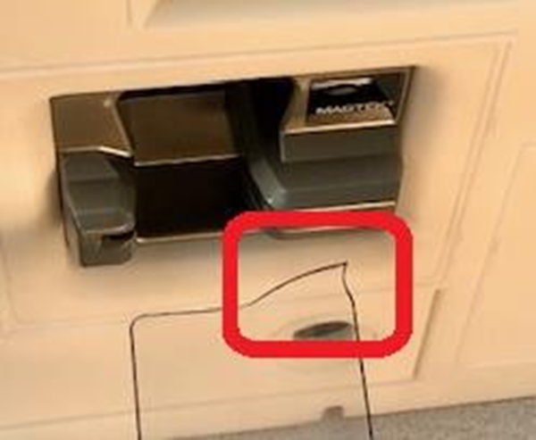
To clean the oDynamo card insertion slot using the MagTek debris clearing tool, follow these steps. MagTek recommends performing this preventive maintenance regularly, depending on usage of the devices you are cleaning. Ideally maintenance would be performed before debris accumulates and renders the device non-functional:
Gather one of the debris cleaning tools from the kit. Turn the tool so its hook corner is on the right side, pointing toward the card insertion slot.
Push the tool straight into the card insertion slot all the way until you feel it touch the back wall.
Push the butt end of the tool to the left. This pivots the tool inside the device and pushes the hook against the back right corner of the card insertion slot.
Continue pushing the tool to the left so it stays engaged with the right wall of the slot, and slowly pull the tool out, scraping the right wall of the card insertion slot clean as you pull.
Repeat the scraping motion 2-3 times.
Turn the tool over so the hook points to the left, and repeat the same steps 2-3 times.
Document Number D998200314-10
Table 1.1 - Revisions
Rev Number
Date
Notes
10
June 11, 2019
This class is a subclass of MTCMSMessage. This class instantiates an MTCMSMessages instance with MessageID value set to the Response message type.
This constructor method builds and initializes an MTCMSResponseMessage instance with the provided values.
public void MTCMSResponseMessage(int applicationID, int commandID, int dataTag, byte[] data)Parameters:
Parameter
Description
applicationID
Return Value: None
This class is a subclass of MTCMSMessage. This class instantiates an MTCMSMessages instance with MessageID value set to the Notification message type.
This constructor method builds and initializes an MTCMSNotificationtMessage instance with the provided values.
public void MTCMSNotificationMessage(int applicationID, int commandID,
int dataTag, byte[] data)Parameters:
Parameter
Description
applicationID
Return Value: None
OEM insertion readers are designed for seamless integration into kiosks, payment terminals, unattended kiosks, fuel pumps, and other self‑service environments; this page provides documentation including mechanical drawings, developer guides, firmware downloads, and setup instructions to embed reliable card reading into your own hardware designs.
Product
Description
A small‑form‑factor device that combines a 3‑track magnetic stripe secure card reader authenticator with contact EMV chip reading, and can be paired with DynaWave to add contactless/NFC capabilities, offering a flexible hybrid solution.
For the most up-to-date information about the device’s EMV Terminal Configuration, EMV Terminal Type, EMV Terminal Capabilities, and Additional EMV Terminal Capabilities, see the EMVCo Letter Of Approval (LOA) for the device:
In a web browser, open www.emvco.com.
Follow the Approvals and Certifications link.
Expand the navigation tree to Terminal Type Approval > Approved Products, and follow the Level/Contact Approved Application Kernels link.
Alternatively you may try
Find the table for products made by MagTek, Inc. and locate the table row for the device you are working with.
Click the attachment icon at the end of the row to open the Letter of Approval for that device.
Manual Part Number: D998200160-20
REGISTERED TO ISO 9001:2015
Information in this publication is subject to change without notice and may contain technical inaccuracies or graphical discrepancies. Changes or improvements made to this product will be updated in the next publication release. No part of this document may be reproduced or transmitted in any form or by any means, electronic or mechanical, for any purpose, without the express written permission of MagTek, Inc.
MagTek® is a registered trademark of MagTek, Inc. oDynamo™ is a registered trademark of MagTek, Inc.
Microsoft® and Windows® are registered trademarks of Microsoft Corporation. Java™ and Java Applet™ are registered trademarks of Oracle.
Bluetooth®, Bluetooth® Low Energy, Bluetooth® LE are registered trademarks of Bluetooth SIG, Inc. All other system names and product names are the property of their respective owners.
The MTCMS Library uses the following constants and data structures.
Device connection types:
Device connection states:
Device information structure:
MTCMSMessage structure:
MagTek warrants that the products sold pursuant to this Agreement will perform in accordance with
MagTek’s published specifications. This warranty shall be provided only for a period of one year from the date of the shipment of the product from MagTek (the “Warranty Period”). This warranty shall apply only to the “Buyer” (the original purchaser, unless that entity resells the product as authorized by MagTek, in which event this warranty shall apply only to the first repurchaser).
During the Warranty Period, should this product fail to conform to MagTek’s specifications, MagTek will, at its option, repair or replace this product at no additional charge except as set forth below. Repair parts and replacement products will be furnished on an exchange basis and will be either reconditioned or new. All replaced parts and products become the property of MagTek. This limited warranty does not include service to repair damage to the product resulting from accident, disaster, unreasonable use, misuse, abuse, negligence, or modification of the product not authorized by MagTek. MagTek reserves the right to examine the alleged defective goods to determine whether the warranty is applicable.
Without limiting the generality of the foregoing, MagTek specifically disclaims any liability or warranty for goods resold in other than MagTek’s original packages, and for goods modified, altered, or treated without authorization by MagTek.
For all MagneSafe ASIC documentation, including programmer’s manuals, the technical reference manual, software/SDKs, and warranty info, please visit the official MageneSafe ASIC Support Page:
Some of the commands and notifications described in this application group are designed to support an external Cryptera Encrypting PIN Pad (EPP). To use these functions, the host software must first serve as a broker to pair oDynamo with the Encrypting PIN Pad.
Be aware that dismounting the EPP erases all pairing information.
Pairing can happen in the field, usually after installation or replacement of the EPP or SCR. Pairing always starts at Step 1.
For all OEM USB Swipe Reader documentation, including programmer’s manuals, the technical reference manual, software/SDKs, and warranty info, please visit the official OEM USB Swipe Reader Support Page:
This page provides essential documentation for the oDynamo hybrid insertion secure card reader authenticator (SCRA), including installation and operation manuals, programmer's references, EMV configuration guides, compliance documents, and supporting resources to enable seamless integration into unattended OEM solutions.
This page provides essential software resources for developing with and managing the oDynamo secure card reader, including platform-specific SDKs for integration across Linux, Windows, .NET, and Java, as well as utility programs for device demonstration, remote configuration, and enterprise‑scale firmware and setting updates.
For all DynaDip documentation, including programmer’s manuals, the technical reference manual, software/SDKs, and warranty info, please visit the official DynaDip Support Page:
For all mDynamo Outdoor Bezel documentation, including programmer’s manuals, the technical reference manual, software/SDKs, and warranty info, please visit the official mDynamo Outdoor Bezel Support Page:
To connect to the oDynamo, follow these steps.
To set up the USB interface with oDynamo on Windows PC, follow these steps:
Connect the oDynamo to the USB port of the Windows PC. Connect the power cable to the oDynamo and wait 1 minute for the device to fully boot up.
Launch the MTCMSNET Demo and select USB as the device type in the Type list box.
This document provides instructions for software developers who want to create .NET / Java software solutions that include a MagTek Common Message Structure (MTCMS) device connected to a Windows PC.
For all SlimSeal documentation, including programmer’s manuals, the technical reference manual, software/SDKs, and warranty info, please visit the official SlimSeal Support Page:
This page provides essential supporting documentation for the oDynamo, including industry magnetic stripe card standards, a white paper on cryptographic algorithm transitions, and a technical bulletin on proper device maintenance and debris removal.
For additional detail, see the EPP documentation provided by Cryptera.
To pair oDynamo with a Cryptera Encrypting PIN Pad, follow these steps:
The operator puts the EPP into the Pre-Activated or Activated state.
The host starts the pairing process by sending the EPP Command START_EXCHANGE (no parameters), Response = P1 P2 P3. If P1=OK, use the entire response (P1P2P3) in the next step.
The host sends oDynamo Command = Command 0x02::0x0A - EPP Pairing Certificate Exchange (C4 = P1P2P3). Make sure C3 value=0 in the response to confirm success. Use the data in C4 (excluding the tag and length) in the next step.
The host sends the EPP Command GENERATE_KEK using the data from the previous step as the parameters. Response = P1 P2 P3. If P1=OK, use the entire response (P1P2P3) for the next step.
The host sends oDynamo Command 0x02::0x0C - EPP Pairing Load KEK (C4 = data from the previous step). Check the oDynamo response to make sure C3 value is 0x00 = OK before proceeding.
The host sends the EPP Command FETCH_KEY (P1 = “LINK_KGK”) and receives a response P1 P2. If P1 = OK, use the data in P2 for the next step.
The host sends oDynamo Command 0x02::0x0D - EPP Pairing Load Derivation Key (C4 = the data from the previous step). Check the oDynamo response to verify C3 value is zero. C4 data is a 3 byte Key Check Value. Save this for the final step.
The host sends the EPP Command GET_KCV (“LINK_KGK”). The EPP responds with parameters = Status, KCVZERO, KCVSELF.
The host compares the 3 byte Key Check Value from oDynamo with the 3-byte KCVZERO value from the previous step. If they match, pairing is complete.
The host can re-check the pairing status at any time by comparing key check values (KCV). The host retrieves the KCV from oDynamo by sending Command 0x02::0x0E - Get Key / Certificate Information with info ID=7, and retrieves a corresponding KCV from the EPP using GET_KCV (“LINK_KGK”) like the steps above. If the values match, pairing is confirmed. If they don’t match, repeat the full pairing process described above.
Initial Release
ApplicationID value
commandID
CommandID value
dataTag
Data Tag value
data
Data value
ApplicationID value
commandID
CommandID value
dataTag
Data Tag value
data
Data value
Italy
0724
Spain
0276
Germany
656E
English (en)
6465
German (de)
Authorization (“RMA”) number must accompany all returns. Buyers may obtain an RMA number by contacting MagTek Support Services at support@magtek.com
EACH BUYER UNDERSTANDS THAT THIS MAGTEK PRODUCT IS OFFERED AS-IS. MAGTEK MAKES NO OTHER WARRANTY, EXPRESS OR IMPLIED, AND MAGTEK DISCLAIMS ANY WARRANTY OF ANY OTHER KIND, INCLUDING ANY WARRANTY OF MERCHANTABILITY OR FITNESS FOR A PARTICULAR PURPOSE.
IF THIS PRODUCT DOES NOT CONFORM TO MAGTEK’S SPECIFICATIONS, THE SOLE REMEDY SHALL BE REPAIR OR REPLACEMENT AS PROVIDED ABOVE. MAGTEK’S LIABILITY, IF ANY, SHALL IN NO EVENT EXCEED THE TOTAL AMOUNT PAID TO MAGTEK UNDER THIS AGREEMENT. IN NO EVENT WILL MAGTEK BE LIABLE TO THE BUYER FOR ANY DAMAGES, INCLUDING ANY LOST PROFITS, LOST SAVINGS, OR OTHER INCIDENTAL OR CONSEQUENTIAL DAMAGES ARISING OUT OF THE USE OF, OR INABILITY TO USE, SUCH PRODUCT, EVEN IF MAGTEK HAS BEEN ADVISED OF THE POSSIBILITY OF SUCH DAMAGES, OR FOR ANY CLAIM BY ANY OTHER PARTY.
Limitation On Liability
EXCEPT AS PROVIDED IN THE SECTIONS RELATING TO MAGTEK’S LIMITED WARRANTY, MAGTEK’S LIABILITY UNDER THIS AGREEMENT IS LIMITED TO THE CONTRACT PRICE OF THIS PRODUCT.
MAGTEK MAKES NO OTHER WARRANTIES WITH RESPECT TO THE PRODUCT, EXPRESSED OR IMPLIED, EXCEPT AS MAY BE STATED IN THIS AGREEMENT, AND MAGTEK DISCLAIMS ANY IMPLIED WARRANTY, INCLUDING WITHOUT LIMITATION ANY IMPLIED WARRANTY OF MERCHANTABILITY OR FITNESS FOR A PARTICULAR PURPOSE.
MAGTEK SHALL NOT BE LIABLE FOR CONTINGENT, INCIDENTAL, OR CONSEQUENTIAL DAMAGES TO PERSONS OR PROPERTY. MAGTEK FURTHER LIMITS ITS LIABILITY OF ANY KIND WITH RESPECT TO THE PRODUCT, INCLUDING NEGLIGENCE ON ITS PART, TO THE CONTRACT PRICE FOR THE GOODS.
MAGTEK’S SOLE LIABILITY AND BUYER’S EXCLUSIVE REMEDIES ARE STATED IN THIS SECTION AND IN THE SECTION RELATING TO MAGTEK’S LIMITED WARRANTY.
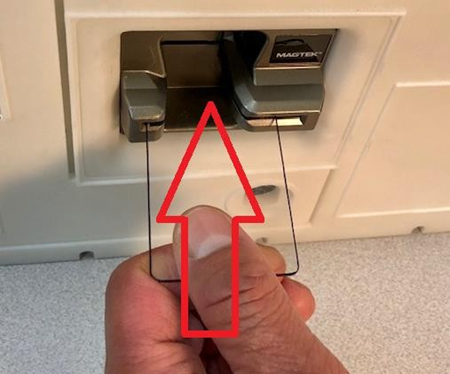
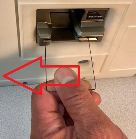

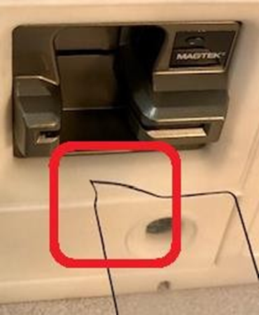
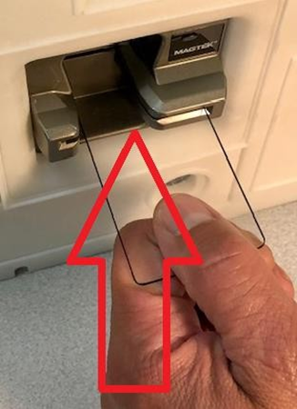
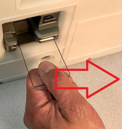
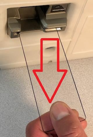
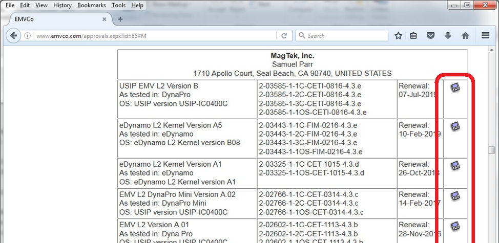
Java Applet
· Windows 7
· Windows 8, 8.1
· Windows 10
Tested web browsers:
· Internet Explorer 11
· Java Runtime requirements: Java 8.
· Tested Java Runtime Environments: 8u221
Language
Requirements
.NET
· Windows 7
· Windows 8, 8.1
· Windows 10
· Microsoft .NET Framework 4.5 or above.
Java Library
· Windows 7
· Windows 8, 8.1
· Windows 10
· Java Build Platform: JDK 1.8, 32-bit and above.
· Minimum Java Runtime requirement: 8
openDevice();const char* dataString = “C00101C10100C20114”;
sendDataString(dataString);unsigned char* dataBytes =
{0xC0,0x01,0x01,0xC1,0x01,0x00,0xC2,0x01,0x14};
sendDataBytes(dataBytes,9);MTCMSMessage* message = CreateMTCMSMessage(0x01,0x00,0x14, NULL,0,
false);
sendMTCMSMessage(message);
ReleaseMTCMSMessage(message);void _stdcall OnDeviceConnectionStateChanged(void* sender,
MTConnectionState state)
{
switch (state)
{
case MTConnectionState::Connected:
Log(_T("[Connected]"));
break;
case MTConnectionState::Connecting:
Log(_T("[Connecting...]"));
break;
case MTConnectionState::Disconnecting:
Log(_T("[Disconnecting...]"));
break;
case MTConnectionState::Disconnected:
Log(_T("[Disconnected]"));
break;
}
}void stdcall OnDeviceResponseMessage(void* sender, const
MTCMSMessage* response)
{
processResponseMessage(response);
}void stdcall OnDeviceNotificationMessage(void* sender, const
MTCMSMessage* notification)
{
processNotificationMessage(notification);
}closeDevice();enum MTConnectionType
{
USB, IP,
Serial
};enum MTConnectionState
{
Disconnected,
Connecting,
Error,
Connected,
Disconnecting
};struct MTDeviceInformation
{
const char* Id;
const char* Name;
const char* Address;
const char* ProductId;
};struct MTCMSMessage
{
int messageType;
int applicationID;
int commandID;
int resultCode;
int dataTag;
const unsigned char* data;
int dataLength;
const unsigned char* messageBytes;
int messageBytesLength;
};MTDevice device = new MTDevice(); if (device != null)
{
device.setConnectionType(MTConnectionType.USB);
device += OnDeviceConnectionStateChanged;
device += onDeviceResponseMessage;
device += onDeviceNotificationMessage;
}if (device != null)
{
device.openDevice();
}String dataString = “C00101C10100C20114”;
device.sendDataString(dataString);Byte[] dataBytes = new Byte[9] {0xC0,0x01,0x01,
0xC1,0x01,0x00,
0xC2,0x01,0x14};
device.sendDataBytes(dataBytes);MTCMSMessage message = new MTCMSMessage(0x01,0x00,0x14, 0xC4, null);
device.sendMTCMSMessage(message);MTCMSRequestMessage request = new MTCMSRequestMessage
(0x00,0x14, 0xC4, false);
device.sendMTCMSMessage(request);protected void OnDeviceConnectionStateChanged(object sender,
MTConnectionState state)
{
if (state == MTConnectionState.Connected)
{
sendToDisplay(“Device is Connected”);
}
else if (state == MTConnectionState.Disconnected)
{
sendToDisplay(“Device is Disconnected”);
}
}protected void OnDeviceResponseMessage(object sender,
MTCMSResponseMessage response)
{
sendToDisplay(“[Response Message]”
sendToDisplay(“AppID: ” + response.getApplicationID());
sendToDisplay(“CommandID: ” + response.getCommandID());
sendToDisplay(“ResultCode: ” + response.getResultCode());
}protected void OnDeviceNotificationMessage(object sender,
MTCMSNotificationMessage notification)
{
sendToDisplay(“[Notification Message]”
sendToDisplay(“AppID: ” notification. getApplicationID() );
sendToDisplay(“CommandID: ” + notification.getCommandID());
sendToDisplay(“ResultCode: ” + notification.getResultCode());
}if (device != null)
{
device.closeDevice();
}Table 0.1 Revisions
Rev Number
Date
Notes
10
05/24/2018
Initial Release
20
09/17/2019
IMPORTANT: YOU SHOULD CAREFULLY READ ALL THE TERMS, CONDITIONS AND RESTRICTIONS OF THIS LICENSE AGREEMENT BEFORE INSTALLING THE SOFTWARE PACKAGE. YOUR INSTALLATION OF THE SOFTWARE PACKAGE PRESUMES YOUR ACCEPTANCE OF THE TERMS, CONDITIONS, AND RESTRICTIONS CONTAINED IN THIS AGREEMENT. IF YOU DO NOT AGREE WITH THESE TERMS, CONDITIONS, AND RESTRICTIONS, PROMPTLY RETURN THE SOFTWARE PACKAGE AND ASSOCIATED DOCUMENTATION TO THE ADDRESS ON THE FRONT PAGE OF THIS DOCUMENT, ATTENTION: CUSTOMER SUPPORT.
TERMS, CONDITIONS, AND RESTRICTIONS
MagTek, Incorporated (the "Licensor") owns and has the right to distribute the described software and documentation, collectively referred to as the "Software."
LICENSE: Licensor grants you (the "Licensee") the right to use the Software in conjunction with MagTek products. LICENSEE MAY NOT COPY, MODIFY, OR TRANSFER THE SOFTWARE IN WHOLE OR IN PART EXCEPT AS EXPRESSLY PROVIDED IN THIS AGREEMENT. Licensee
may not decompile, disassemble, or in any other manner attempt to reverse engineer the Software. Licensee shall not tamper with, bypass, or alter any security features of the software or attempt to do so.
TRANSFER: Licensee may not transfer the Software or license to the Software to another party without the prior written authorization of the Licensor. If Licensee transfers the Software without authorization, all rights granted under this Agreement are automatically terminated.
COPYRIGHT: The Software is copyrighted. Licensee may not copy the Software except for archival purposes or to load for execution purposes. All other copies of the Software are in violation of this Agreement.
TERM: This Agreement is in effect as long as Licensee continues the use of the Software. The Licensor also reserves the right to terminate this Agreement if Licensee fails to comply with any of the terms, conditions, or restrictions contained herein. Should Licensor terminate this Agreement due to Licensee's failure to comply, Licensee agrees to return the Software to Licensor. Receipt of returned Software by the Licensor shall mark the termination.
LIMITED WARRANTY: Licensor warrants to the Licensee that the disk(s) or other media on which the Software is recorded are free from defects in material or workmanship under normal use.
THE SOFTWARE IS PROVIDED AS IS. LICENSOR MAKES NO OTHER WARRANTY OF ANY KIND, EITHER EXPRESS OR IMPLIED, INCLUDING, BUT NOT LIMITED TO, THE IMPLIED WARRANTIES OF MERCHANTABILITY AND FITNESS FOR A PARTICULAR PURPOSE.
Because of the diversity of conditions and PC hardware under which the Software may be used, Licensor does not warrant that the Software will meet Licensee specifications or that the operation of the Software will be uninterrupted or free of errors.
IN NO EVENT WILL LICENSOR BE LIABLE FOR ANY DAMAGES, INCLUDING ANY LOST PROFITS, LOST SAVINGS, OR OTHER INCIDENTAL OR CONSEQUENTIAL DAMAGES ARISING OUT OF THE USE, OR INABILITY TO USE, THE SOFTWARE. Licensee's sole remedy in
the event of a defect in material or workmanship is expressly limited to replacement of the Software disk(s) if applicable.
GOVERNING LAW: If any provision of this Agreement is found to be unlawful, void, or unenforceable, that provision shall be removed from consideration under this Agreement and will not affect the enforceability of any of the remaining provisions. This Agreement shall be governed by the laws of the State of California and shall inure to the benefit of MagTek, Incorporated, its successors or assigns.
ACKNOWLEDGMENT: LICENSEE ACKNOWLEDGES THAT HE HAS READ THIS AGREEMENT, UNDERSTANDS ALL OF ITS TERMS, CONDITIONS, AND RESTRICTIONS, AND AGREES TO BE BOUND BY THEM. LICENSEE ALSO AGREES THAT THIS AGREEMENT SUPERSEDES ANY AND ALL VERBAL AND WRITTEN COMMUNICATIONS BETWEEN LICENSOR AND LICENSEE OR THEIR ASSIGNS RELATING TO THE SUBJECT MATTER OF THIS AGREEMENT.
QUESTIONS REGARDING THIS AGREEMENT SHOULD BE ADDRESSED IN WRITING TO MAGTEK, INCORPORATED, ATTENTION: CUSTOMER SUPPORT, AT THE ADDRESS LISTED IN THIS DOCUMENT, OR E-MAILED TO SUPPORT@MAGTEK.COM.
Technical references for developers including the Commands Programmer's Manual, the Microsoft .NET/Java/Applet Programmer's Manual, the MTCMS Demo guide, and the SCRA EMV Flowchart
Supporting resources such as the EMV Configuration Software Instructions for verifying EMV configuration via USB, the debris clearing tool manual , the device inspection manual for tamper detection and PCI PTS compliance, and marketing brochures including the oDynamo Hybrid Card Reader Brochure.
Reference Section
Information Available
End‑user and integrator documentation including the Installation and Operation Manual for design guidelines, mounting instructions, and host connectivity, along with the MagTek Reader Management System guide for firmware and CAPK updates.
Need Help?
For additional support, please contact MagTek Support:
Technical Support:
📧 Email:
Press the Scan button to scan for connected USB devices.
Select the Device ID and press the Connect button to open the device.
If Ethernet interface will be used, select IP Address from the Info list box and press the Get Info button. Note the value retuned from the response as this will be used for the IP Address when connecting via Ethernet Interface.
To set up the Ethernet interface with oDynamo on Windows PC, follow these steps:
Connect the oDynamo to the Ethernet port on the Ethernet hub, connect the power cable to the oDynamo and wait 1 minute for the device to fully boot up.
Launch the MTCMSNET Demo and select IP as the device in the Type list box.
Enter the IP address attained from the last step from connection via USB Interface section 2.1, then press the Connect button to open the device. The MTCMS NET Demo may take up to 30 seconds before disconnecting if the device cannot be connected.
To set up the Serial interface with oDynamo on Windows PC, follow these steps:
Connect the oDynamo to the Serial port, connect the power cable to the oDynamo and wait 1 minute for the device to fully boot up.
Launch the MTCMSNET Demo and select Serial as the device in the Type list box.
Select the Com number the device is attached to and press the Connect button to open the device.
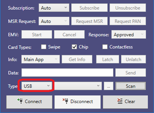
A technical bulletin that provides illustrated step-by-step instructions for correctly using the MagTek debris clearing tool to remove accumulated debris from the oDynamo's card insertion slot, helping to maintain device functionality and prevent mechanical damage.
Reference Section
Information Available
Common technical details for magnetic stripe cards.
A white paper that addresses NIST Special Publication 800-131A regarding the transition away from Two-Key TDEA encryption, outlining MagTek's approach to cryptographic algorithm migration.
Need Help?
For additional support, please contact MagTek Support:
Technical Support:
📧 Email:
The IP34-rated mDynamo with Outdoor Bezel is a compact EMV chip card reading module built on the MagneSafe security architecture, featuring a spring‑loaded door to block dust and moisture for reliable integration into both indoor and outdoor unattended kiosks.
A manually operated, push‑in magnetic stripe reader that minimizes incorrect card insertion with an optional dual‑head design and an open‑frame construction that keeps the card slot free of debris, available in TTL, RS‑232, and USB interfaces.
oDynamo is a PCI PTS 5.x SRED‑certified, secure insertion card reader authenticator for OEM solutions that reads both magnetic stripe and EMV contact chip data, supports USB, Ethernet, and RS‑232 connections, and features a sealed, liquid‑impervious chassis designed for harsh unattended environments like gas pumps, ATMs, and vending machines.
Secure card reader authenticator that reads up to three tracks from ISO and AAMVA cards, featuring a sealed, tamper‑resistant design for unattended and outdoor installations.
Secure card reader authenticator that reads up to three tracks from ISO and AAMVA cards, featuring a sealed, tamper‑resistant design for unattended and outdoor installations.
Need Help?
For additional support, please contact MagTek Support:
Technical Support:
📧 Email: support@magtek.com
📞 Phone: 1-562-546-6800 (US)
🕐 Hours: Monday-Friday, 5:30 AM - 5:00 PM PST
Online Resources:
🌐 Support Portal: developer.magtek.com
Documentation Feedback:
Help us improve this documentation!
Description
Summary
Essential software resources for developing with and managing the oDynamo secure card reader.
Need Help?
For additional support, please contact MagTek Support:
Technical Support:
📧 Email: support@magtek.com
📞 Phone: 1-800-788-6835 (US) | +1-562-546-6616 (International)
🕐 Hours: Monday-Friday, 6:00 AM - 5:00 PM PST
Online Resources:
🌐 Official Site:
💬 Developer Forum:
Documentation Feedback:
Help us improve this documentation!
Need Help?
For additional support, please contact MagTek Support:
Technical Support:
📧 Email: support@magtek.com
📞 Phone: 1-562-546-6800 (US)
🕐 Hours: Monday-Friday, 5:30 AM - 5:00 PM PST
Online Resources:
🌐 Support Portal: developer.magtek.com
Documentation Feedback:
Help us improve this documentation!
Need Help?
For additional support, please contact MagTek Support:
Technical Support:
📧 Email: support@magtek.com
📞 Phone: 1-562-546-6800 (US)
🕐 Hours: Monday-Friday, 5:30 AM - 5:00 PM PST
Online Resources:
🌐 Support Portal: developer.magtek.com
Documentation Feedback:
Help us improve this documentation!
Need Help?
For additional support, please contact MagTek Support:
Technical Support:
📧 Email: support@magtek.com
📞 Phone: 1-562-546-6800 (US)
🕐 Hours: Monday-Friday, 5:30 AM - 5:00 PM PST
Online Resources:
🌐 Support Portal: developer.magtek.com
Documentation Feedback:
Help us improve this documentation!
Need Help?
For additional support, please contact MagTek Support:
Technical Support:
📧 Email: support@magtek.com
📞 Phone: 1-562-546-6800 (US)
🕐 Hours: Monday-Friday, 5:30 AM - 5:00 PM PST
Online Resources:
🌐 Support Portal: developer.magtek.com
Documentation Feedback:
Help us improve this documentation!
Need Help?
For additional support, please contact MagTek Support:
Technical Support:
📧 Email: support@magtek.com
📞 Phone: 1-562-546-6800 (US)
🕐 Hours: Monday-Friday, 5:30 AM - 5:00 PM PST
Online Resources:
🌐 Support Portal: developer.magtek.com
Documentation Feedback:
Help us improve this documentation!
The library will call this function when device information is available.
typedef void ( stdcall * OnDeviceListEvent)(
void* sender,
MTConnectionType connectionType,
int deviceCount,
MTDeviceInformation* deviceList);Parameter
Description
sender
Object representing the publisher of the event.
connectionType
Return Value: None
This event occurs when the connection state of the device is changed.
This event occurs when a response is received from the device.
Return Value: None
This event occurs when a response is received from the device.
This event occurs when a response is received from the device.
Copyright © 2006 – 2018 MagTek, Inc. Printed in the United States of America
Information in this publication is subject to change without notice and may contain technical inaccuracies or graphical discrepancies. Changes or improvements made to this product will be updated in the next publication release. No part of this document may be reproduced or transmitted in any form or by any means, electronic or mechanical, for any purpose, without the express written permission of MagTek, Inc.
MagTek® is a registered trademark of MagTek, Inc. oDynamo™ is a trademarks of MagTek, Inc.
Microsoft® and Windows® are registered trademarks of Microsoft Corporation.
All other system names and product names are the property of their respective owners.
Table 0.1 – Revisions
SOFTWARE LICENSE AGREEMENT
IMPORTANT: YOU SHOULD CAREFULLY READ ALL THE TERMS, CONDITIONS AND RESTRICTIONS OF THIS LICENSE AGREEMENT BEFORE INSTALLING THE SOFTWARE PACKAGE. YOUR INSTALLATION OF THE SOFTWARE PACKAGE PRESUMES YOUR ACCEPTANCE OF THE TERMS, CONDITIONS, AND RESTRICTIONS CONTAINED IN THIS AGREEMENT. IF YOU DO NOT AGREE WITH THESE TERMS, CONDITIONS, AND RESTRICTIONS, PROMPTLY RETURN THE SOFTWARE PACKAGE AND ASSOCIATED DOCUMENTATION TO THE ADDRESS ON THE FRONT PAGE OF THIS DOCUMENT, ATTENTION: CUSTOMER SUPPORT.
MagTek, Incorporated (the "Licensor") owns and has the right to distribute the described software and documentation, collectively referred to as the "Software."
LICENSE: Licensor grants you (the "Licensee") the right to use the Software in conjunction with MagTek products. LICENSEE MAY NOT COPY, MODIFY, OR TRANSFER THE SOFTWARE IN WHOLE OR IN PART EXCEPT AS EXPRESSLY PROVIDED IN THIS AGREEMENT. Licensee
may not decompile, disassemble, or in any other manner attempt to reverse engineer the Software. Licensee shall not tamper with, bypass, or alter any security features of the software or attempt to do so.
TRANSFER: Licensee may not transfer the Software or license to the Software to another party without the prior written authorization of the Licensor. If Licensee transfers the Software without authorization, all rights granted under this Agreement are automatically terminated.
COPYRIGHT: The Software is copyrighted. Licensee may not copy the Software except for archival purposes or to load for execution purposes. All other copies of the Software are in violation of this Agreement.
TERM: This Agreement is in effect as long as Licensee continues the use of the Software. The Licensor also reserves the right to terminate this Agreement if Licensee fails to comply with any of the terms, conditions, or restrictions contained herein. Should Licensor terminate this Agreement due to Licensee's failure to comply, Licensee agrees to return the Software to Licensor. Receipt of returned Software by the Licensor shall mark the termination.
LIMITED WARRANTY: Licensor warrants to the Licensee that the disk(s) or other media on which the Software is recorded are free from defects in material or workmanship under normal use.
THE SOFTWARE IS PROVIDED AS IS. LICENSOR MAKES NO OTHER WARRANTY OF ANY KIND, EITHER EXPRESS OR IMPLIED, INCLUDING, BUT NOT LIMITED TO, THE IMPLIED WARRANTIES OF MERCHANTABILITY AND FITNESS FOR A PARTICULAR PURPOSE.
Because of the diversity of conditions and PC hardware under which the Software may be used, Licensor does not warrant that the Software will meet Licensee specifications or that the operation of the Software will be uninterrupted or free of errors.
IN NO EVENT WILL LICENSOR BE LIABLE FOR ANY DAMAGES, INCLUDING ANY LOST PROFITS, LOST SAVINGS, OR OTHER INCIDENTAL OR CONSEQUENTIAL DAMAGES ARISING OUT OF THE USE, OR INABILITY TO USE, THE SOFTWARE. Licensee's sole remedy in
the event of a defect in material or workmanship is expressly limited to replacement of the Software disk(s) if applicable.
GOVERNING LAW: If any provision of this Agreement is found to be unlawful, void, or unenforceable, that provision shall be removed from consideration under this Agreement and will not affect the enforceability of any of the remaining provisions. This Agreement shall be governed by the laws of the State of California and shall inure to the benefit of MagTek, Incorporated, its successors or assigns.
ACKNOWLEDGMENT: LICENSEE ACKNOWLEDGES THAT HE HAS READ THIS AGREEMENT, UNDERSTANDS ALL OF ITS TERMS, CONDITIONS, AND RESTRICTIONS, AND AGREES TO BE BOUND BY THEM. LICENSEE ALSO AGREES THAT THIS AGREEMENT SUPERSEDES ANY AND ALL VERBAL AND WRITTEN COMMUNICATIONS BETWEEN LICENSOR AND LICENSEE OR THEIR ASSIGNS RELATING TO THE SUBJECT MATTER OF THIS AGREEMENT.
QUESTIONS REGARDING THIS AGREEMENT SHOULD BE ADDRESSED IN WRITING TO MAGTEK, INCORPORATED, ATTENTION: CUSTOMER SUPPORT, AT THE ADDRESS LISTED IN THIS DOCUMENT, OR E-MAILED TO
Manual Part Number: D998200159-10 REGISTERED TO ISO 9001:2015 MagTek I 1710 Apollo Court I Seal Beach, CA 90740 I Phone: (562) 546-6400 I Technical Support: (888) 624-8350 www.magtek.com Copyright © 2006-2018 MagTek, Inc. Printed in the United States of America Information in this publication is subject to change without notice and may contain technical inaccuracies or graphical discrepancies. Changes or improvements made to this product will be updated in the next publication release. No part of this document may be reproduced or transmitted in any form or by any means, electronic or mechanical, for any purpose, without the express written permission of MagTek, Inc. MagTek® is a registered trademark of MagTek, Inc. Microsoft® and Windows® are registered trademarks of Microsoft Corporation. All other system names and product names are the property of their respective owners.
Table 0.1 Revisions
Rev Number
Date
SOFTWARE LICENSE AGREEMENT
IMPORTANT: YOU SHOULD CAREFULLY READ ALL THE TERMS, CONDITIONS AND RESTRICTIONS OF THIS LICENSE AGREEMENT BEFORE INSTALLING THE SOFTWARE PACKAGE. YOUR INSTALLATION OF THE SOFTWARE PACKAGE PRESUMES YOUR ACCEPTANCE OF THE TERMS, CONDITIONS, AND RESTRICTIONS CONTAINED IN THIS AGREEMENT. IF YOU DO NOT AGREE WITH THESE TERMS, CONDITIONS, AND RESTRICTIONS, PROMPTLY RETURN THE SOFTWARE PACKAGE AND ASSOCIATED DOCUMENTATION TO THE ADDRESS ON THE FRONT PAGE OF THIS DOCUMENT, ATTENTION: CUSTOMER SUPPORT.
TERMS, CONDITIONS, AND RESTRICTIONS MagTek, Incorporated (the "Licensor") owns and has the right to distribute the described software and documentation, collectively referred to as the "Software."
LICENSE: Licensor grants you (the "Licensee") the right to use the Software in conjunction with MagTek products.
LICENSEE MAY NOT COPY, MODIFY, OR TRANSFER THE SOFTWARE IN WHOLE OR IN PART EXCEPT AS EXPRESSLY PROVIDED IN THIS AGREEMENT.
Licensee may not decompile, disassemble, or in any other manner attempt to reverse engineer the Software. Licensee shall not tamper with, bypass, or alter any security features of the software or attempt to do so.
TRANSFER: Licensee may not transfer the Software or license to the Software to another party without the prior written authorization of the Licensor. If Licensee transfers the Software without authorization, all rights granted under this Agreement are automatically terminated.
COPYRIGHT: The Software is copyrighted. Licensee may not copy the Software except for archival purposes or to load for execution purposes. All other copies of the Software are in violation of this Agreement.
TERM: This Agreement is in effect as long as Licensee continues the use of the Software. The Licensor also reserves the right to terminate this Agreement if Licensee fails to comply with any of the terms, conditions, or restrictions contained herein. Should Licensor terminate this Agreement due to Licensee's failure to comply, Licensee agrees to return the Software to Licensor. Receipt of returned Software by the Licensor shall mark the termination.
LIMITED WARRANTY: Licensor warrants to the Licensee that the disk(s) or other media on which the Software is recorded are free from defects in material or workmanship under normal use.
THE SOFTWARE IS PROVIDED AS IS. LICENSOR MAKES NO OTHER WARRANTY OF ANY KIND, EITHER EXPRESS OR IMPLIED, INCLUDING, BUT NOT LIMITED TO, THE IMPLIED WARRANTIES OF MERCHANTABILITY AND FITNESS FOR A PARTICULAR PURPOSE.
Because of the diversity of conditions and PC hardware under which the Software may be used, Licensor does not warrant that the Software will meet Licensee specifications or that the operation of the Software will be uninterrupted or free of errors.
IN NO EVENT WILL LICENSOR BE LIABLE FOR ANY DAMAGES, INCLUDING ANY LOST PROFITS, LOST SAVINGS, OR OTHER INCIDENTAL OR CONSEQUENTIAL DAMAGES ARISING OUT OF THE USE, OR INABILITY TO USE, THE SOFTWARE.
Licensee's sole remedy in the event of a defect in material or workmanship is expressly limited to replacement of the Software disk(s) if applicable.
GOVERNING LAW: If any provision of this Agreement is found to be unlawful, void, or unenforceable, that provision shall be removed from consideration under this Agreement and will not affect the enforceability of any of the remaining provisions. This Agreement shall be governed by the laws of the State of California and shall inure to the benefit of MagTek, Incorporated, its successors or assigns.
ACKNOWLEDGMENT: LICENSEE ACKNOWLEDGES THAT HE HAS READ THIS AGREEMENT, UNDERSTANDS ALL OF ITS TERMS, CONDITIONS, AND RESTRICTIONS, AND AGREES TO BE BOUND BY THEM. LICENSEE ALSO AGREES THAT THIS AGREEMENT SUPERSEDES ANY AND ALL VERBAL AND WRITTEN COMMUNICATIONS BETWEEN LICENSOR AND LICENSEE OR THEIR ASSIGNS RELATING TO THE SUBJECT MATTER OF THIS AGREEMENT.
QUESTIONS REGARDING THIS AGREEMENT SHOULD BE ADDRESSED IN WRITING TO MAGTEK, INCORPORATED, ATTENTION: CUSTOMER SUPPORT, AT THE ADDRESS LISTED IN THIS DOCUMENT, OR E-MAILED TO SUPPORT@MAGTEK.COM.
This page provides essential user manuals for the oDynamo hybrid insertion secure card reader authenticator (SCRA), including installation and operation guides, quick start instructions, and EMV configuration tools to support seamless integration into unattended OEM solutions.
Reference Section
Information Available
A concise, step-by-step guide designed to help developers quickly connect the oDynamo to a host system and activate it for testing and development using the included development kit.
Updating EMV Tags/CAPKs requires the RMS Windows application. Download and install the MagTek Reader Management System.
Launch the RMS application and select USB as the Interface.
Select the device type either DynPro for DynaPro Go devices, or oDynamo for oDynamo devices.
Click Scan to scan for USB devices.
Available devices will appear in the Devices field. Select the desired device and click Open .
Check EMV Tags/CAPKs and click Update
The update status bar will appear in green at the bottom of the window, and log the update and results.
Once the update has finished loading, the Output log will display "SUCCESS," confirming that all updates have been applied and the process is complete.
For all PermaSeal documentation, including programmer’s manuals, the technical reference manual, software/SDKs, and warranty info, please visit the official PermaSeal Support Page:
Need Help?
For additional support, please contact MagTek Support:
Technical Support:
📧 Email:
This page provides the compliance documentation required to maintain PCI PTS approval for the oDynamo hybrid insertion secure card reader authenticator (SCRA), including the device and package inspection guides for tamper detection and physical security verification.
Reference Section
Information Available
A step‑by‑step service and repair manual that explains how to visually inspect the oDynamo’s enclosure, bezel, screws, ventilation holes, dismount switches, and connection ports for signs of tampering or unauthorized modification to help ensure the device remains PCI PTS 5.x SRED compliant before deployment.
These methods allows building CMS messages to be used in communications with MagTek CMS devices.
This constructor method builds an MTCMSMessage instance with the provided values.
Parameters:
Manual Part Number: D100005143-10
REGISTERED TO ISO 9001:2015
Information in this publication is subject to change without notice and may contain technical inaccuracies or graphical discrepancies. Changes or improvements made to this product will be updated in the next publication release. No part of this document may be reproduced or transmitted in any form or by any means, electronic or mechanical, for any purpose, without the express written permission of MagTek, Inc.
MagTek® is a registered trademark of MagTek, Inc. MagneSafe® is a registered trademark of MagTek, Inc. iDynamo™, and uDynamo are trademarks of MagTek, Inc.
eDynamo™, Dynamag, and DynaMAX are trademarks of MagTek, Inc.
The Bluetooth® word mark and logos are registered trademarks owned by Bluetooth SIG, Inc. and any use of such marks by MagTek is under license.
Update Java System Requirements.
Notes
10
05/25/2018
Initial Release
📞 Phone: 1-562-546-6800 (US)
🕐 Hours: Monday-Friday, 5:30 AM - 5:00 PM PST
Online Resources:
🌐 Support Portal: developer.magtek.com
Documentation Feedback:
Help us improve this documentation! feedback@magtek.com
📞 Phone: 1-562-546-6800 (US)
🕐 Hours: Monday-Friday, 5:30 AM - 5:00 PM PST
Online Resources:
🌐 Support Portal: developer.magtek.com
Documentation Feedback:
Help us improve this documentation! feedback@magtek.com
📞 Phone: 1-562-546-6800 (US)
🕐 Hours: Monday-Friday, 5:30 AM - 5:00 PM PST
Online Resources:
🌐 Support Portal: developer.magtek.com
Documentation Feedback:
Help us improve this documentation! feedback@magtek.com
📞 Phone: 1-562-546-6800 (US)
🕐 Hours: Monday-Friday, 5:30 AM - 5:00 PM PST
Online Resources:
🌐 Support Portal: developer.magtek.com
Documentation Feedback:
Help us improve this documentation! feedback@magtek.com
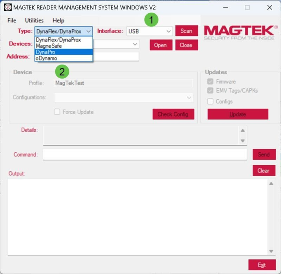
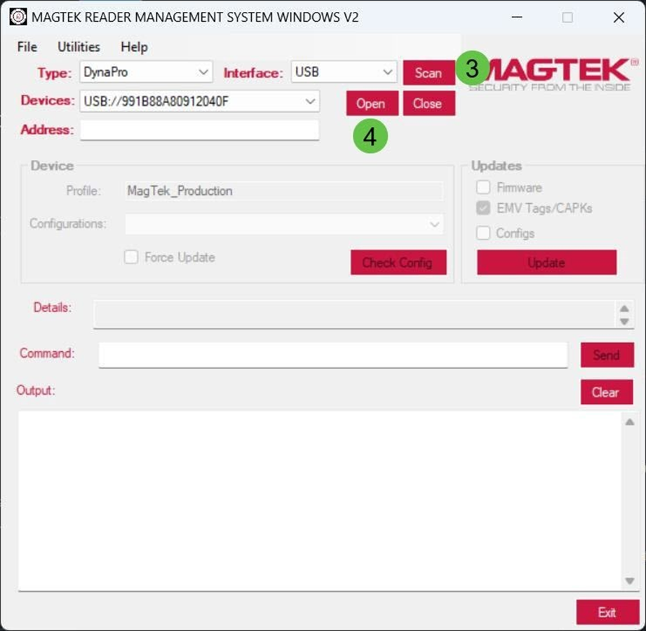
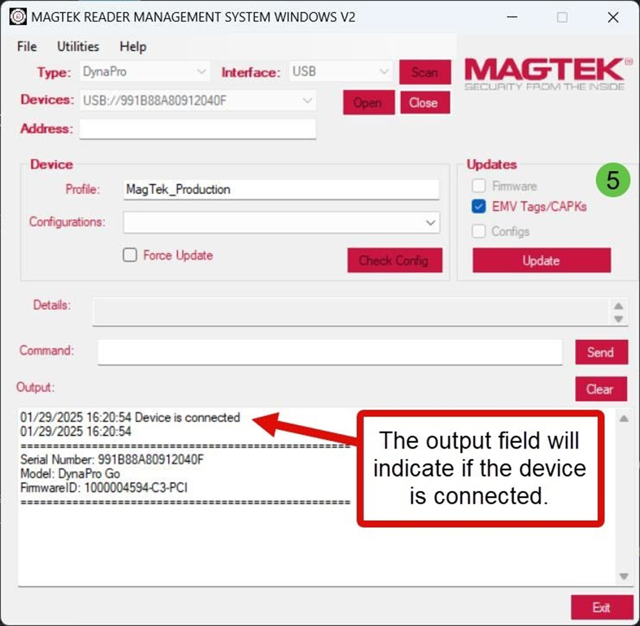
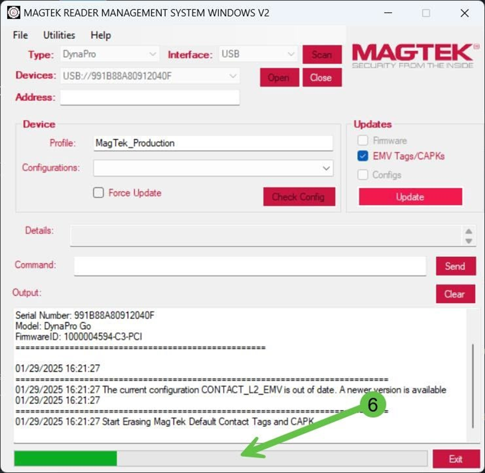
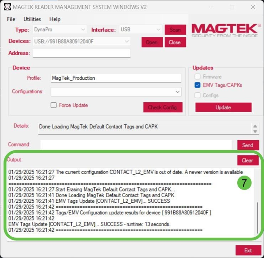
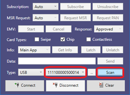
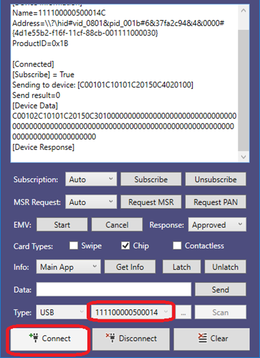
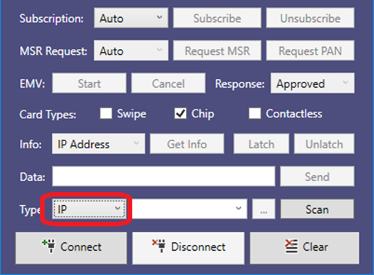
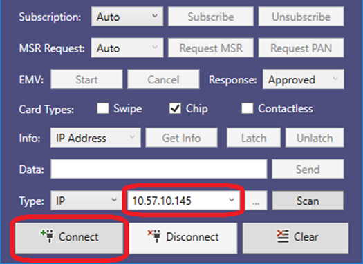
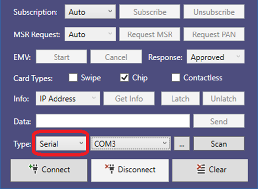
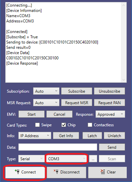
Rev Number
Date
Notes
10
May 21, 2018
Initial release
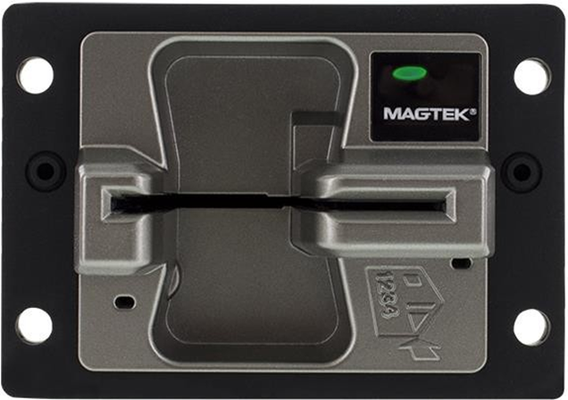
To add the MagTek CMS libraries to a Windows C++ project in Microsoft Visual Studio, follow these steps:
Create or open your project in Visual Studio.
Copy the following DLL file from the MTCMSDemo folders to the library folder of your software project:
MTCMS.dll
In the Visual Studio Solution Explorer, right-click the project and select Add Reference to show the Add Reference window.
Select the Browse tab and press the Browse… button.
Navigate to your library folder, select MTCMS.dll, then press the Add button.
In your custom software, create an instance of MTDevice. For examples, see the source code included with the MTCMSDemo project and/or Appendix A Code Examples.
Begin using the features provided by the MTCMS library
IOS is a trademark or registered trademark of Cisco in the U.S. and other countries and is is used by Apple Inc. under license.
Microsoft®, Windows® and .NET® are registered trademarks of Microsoft Corporation.
EMV® is a registered trademark in the U.S. and other countries and an unregistered trademark elsewhere. The EMV trademark is owned by EMVCo, LLC. The Contactless Indicator mark, consisting of four graduating arcs, is a trademark owned by and used with permission of EMVCo, LLC.
All other system names and product names are the property of their respective owners.
Table 0.1 Revisions
Rev Number
Date
Notes
10
11/15/2019
Initial Release
IMPORTANT: YOU SHOULD CAREFULLY READ ALL THE TERMS, CONDITIONS AND RESTRICTIONS OF THIS LICENSE AGREEMENT BEFORE INSTALLING THE SOFTWARE PACKAGE. YOUR INSTALLATION OF THE SOFTWARE PACKAGE PRESUMES YOUR ACCEPTANCE OF THE TERMS, CONDITIONS, AND RESTRICTIONS CONTAINED IN THIS AGREEMENT. IF YOU DO NOT AGREE WITH THESE TERMS, CONDITIONS, AND RESTRICTIONS, PROMPTLY RETURN THE SOFTWARE PACKAGE AND ASSOCIATED DOCUMENTATION TO THE ADDRESS ON THE FRONT PAGE OF THIS DOCUMENT, ATTENTION: CUSTOMER SUPPORT.
TERMS, CONDITIONS, AND RESTRICTIONS
MagTek, Incorporated (the "Licensor") owns and has the right to distribute the described software and documentation, collectively referred to as the "Software."
LICENSE: Licensor grants you (the "Licensee") the right to use the Software in conjunction with MagTek products. LICENSEE MAY NOT COPY, MODIFY, OR TRANSFER THE SOFTWARE IN WHOLE OR IN PART EXCEPT AS EXPRESSLY PROVIDED IN THIS AGREEMENT. Licensee
may not decompile, disassemble, or in any other manner attempt to reverse engineer the Software. Licensee shall not tamper with, bypass, or alter any security features of the software or attempt to do so.
TRANSFER: Licensee may not transfer the Software or license to the Software to another party without the prior written authorization of the Licensor. If Licensee transfers the Software without authorization, all rights granted under this Agreement are automatically terminated.
COPYRIGHT: The Software is copyrighted. Licensee may not copy the Software except for archival purposes or to load for execution purposes. All other copies of the Software are in violation of this Agreement.
TERM: This Agreement is in effect as long as Licensee continues the use of the Software. The Licensor also reserves the right to terminate this Agreement if Licensee fails to comply with any of the terms, conditions, or restrictions contained herein. Should Licensor terminate this Agreement due to Licensee's failure to comply, Licensee agrees to return the Software to Licensor. Receipt of returned Software by the Licensor shall mark the termination.
LIMITED WARRANTY: Licensor warrants to the Licensee that the disk(s) or other media on which the Software is recorded are free from defects in material or workmanship under normal use.
THE SOFTWARE IS PROVIDED AS IS. LICENSOR MAKES NO OTHER WARRANTY OF ANY KIND, EITHER EXPRESS OR IMPLIED, INCLUDING, BUT NOT LIMITED TO, THE IMPLIED WARRANTIES OF MERCHANTABILITY AND FITNESS FOR A PARTICULAR PURPOSE.
Because of the diversity of conditions and PC hardware under which the Software may be used, Licensor does not warrant that the Software will meet Licensee specifications or that the operation of the Software will be uninterrupted or free of errors.
IN NO EVENT WILL LICENSOR BE LIABLE FOR ANY DAMAGES, INCLUDING ANY LOST PROFITS, LOST SAVINGS, OR OTHER INCIDENTAL OR CONSEQUENTIAL DAMAGES ARISING OUT OF THE USE, OR INABILITY TO USE, THE SOFTWARE. Licensee's sole remedy in
the event of a defect in material or workmanship is expressly limited to replacement of the Software disk(s) if applicable.
GOVERNING LAW: If any provision of this Agreement is found to be unlawful, void, or unenforceable, that provision shall be removed from consideration under this Agreement and will not affect the enforceability of any of the remaining provisions. This Agreement shall be governed by the laws of the State of California and shall inure to the benefit of MagTek, Incorporated, its successors or assigns.
ACKNOWLEDGMENT: LICENSEE ACKNOWLEDGES THAT HE HAS READ THIS AGREEMENT, UNDERSTANDS ALL OF ITS TERMS, CONDITIONS, AND RESTRICTIONS, AND AGREES TO BE BOUND BY THEM. LICENSEE ALSO AGREES THAT THIS AGREEMENT SUPERSEDES ANY AND ALL VERBAL AND WRITTEN COMMUNICATIONS BETWEEN LICENSOR AND LICENSEE OR THEIR ASSIGNS RELATING TO THE SUBJECT MATTER OF THIS AGREEMENT.
QUESTIONS REGARDING THIS AGREEMENT SHOULD BE ADDRESSED IN WRITING TO MAGTEK, INCORPORATED, ATTENTION: CUSTOMER SUPPORT, AT THE ADDRESS LISTED IN THIS DOCUMENT, OR E-MAILED TO SUPPORT@MAGTEK.COM.
This document provides the instructions to use the MTCMSNET Demo. It is part of a larger library of documents designed to assist oDynamo implementers, which includes the following documents available from MagTek:
· D998200160 ODYNAMO PROGRAMMER'S REFERENCE MANUAL (MICROSOFT .NET)
MTConnectionType value: MTConnectionType.USB, MTConnectionType.IP, MTConnectionType.Serial
deviceCount
Number of devices in deviceList.
deviceList
A list of MTDeviceInformation objects.
Parameter
Description
sender
Object representing the publisher of the event.
state
MTConnectionState value indicating the state of the device: MTConnectionState.Disconnected MTConnectionState.Connecting MTConnectionState.Error MTConnectionState.Connected MTConnectionState.Disconnecting
Parameter
Description
sender
Object representing the publisher of the event.
dataString
String representing data received.
Parameter
Description
sender
Object representing the publisher of the event.
response
MTCMSMessage representing data received.
Parameter
Description
sender
Object representing the publisher of the event.
notification
MTCMSMessage representing data received.
typedef void ( stdcall * OnDeviceConnectionStateChangedEvent)(
void* sender,
MTConnectionState state);typedef void ( stdcall * OnDeviceDataStringEvent)(
void* sender,
const char* dataString);typedef void ( stdcall * OnDeviceResponseMessageEvent)( void* sender,
const MTCMSMessage* response);typedef void ( stdcall * OnDeviceNotificationMessageEvent)(
void* sender,
const MTCMSMessage* notification);applicationID
ApplicationID value
commandID
CommandID value
dataTag
Data tag value
data
Data value
dataLength
Length of data value
Return Value: MTCMSMessage structure
This constructor method builds an MTCMSMessage instance with the provided values.
Parameters:
Parameter
Description
messageBytes
Message in byte array value
messageBytesLength
Length of message bytes value
Return Value: MTCMSMessage structure
This constructor method builds an MTCMSMessage instance with the provided values.
Parameters:
Parameter
Description
applicationID
ApplicationID value
commandID
CommandID value
dataTag
Data tag value
Return Value: MTCMSMessage structure
This method releases the resource allocated by calls to CreateMTCMSMessage and CreateMTCMSRequestMessage methods.
Parameters:
Parameter
Description
message
MTCMSMessage to deallocate.
Return Value: None
MTCMS_API MTCMSMessage* CreateMTCMSMessage(
int messageType,
int applicationID,
int commandID,
int dataTag,
const unsigned char* data,
int dataLength);Parameter
Description
messageType
MessageType value
MTCMS_API MTCMSMessage* CreateMTCMSMessageFromBytes(
const unsigned char* messageBytes,
int messageBytesLength);MTCMS_API MTCMSMessage* MTCMSMessage(
int applicationID,
int commandID,
int dataTag,
const unsigned char* data,
int dataLength);MTCMS_API void ReleaseMTCMSMessage(MTCMSMessage* message);A guide that details the process of updating the Certificate Authority Public Keys (CAPKs) and EMV tags in oDynamo devices, ensuring continued compliance with card brand security requirements and transaction authenticity.
A comprehensive manual offering design guidelines, mounting instructions, electrical integration specifications, and operational best practices for embedding the oDynamo into self‑service terminals, kiosks, and other unattended payment solutions.
A document that explains how to use the MagTek EMV Configuration application to verify and manage EMV configurations on an oDynamo connected to a host PC via USB, supporting proper EMV transaction processing.
Need Help?
For additional support, please contact MagTek Support:
Technical Support:
📧 Email: support@magtek.com
📞 Phone: 1-562-546-6800 (US)
🕐 Hours: Monday-Friday, 5:30 AM - 5:00 PM PST
Online Resources:
🌐 Support Portal: developer.magtek.com
Documentation Feedback:
Help us improve this documentation!
The Package Inspection Document provides step-by-step visual and physical verification procedures for detecting tamper evidence on oDynamo packaging—including security tape inspection, seal integrity checks, and serial number validation—to ensure the single‑pack and multi‑pack devices remain PCI compliant before installation.
Need Help?
For additional support, please contact MagTek Support:
Technical Support:
📧 Email: support@magtek.com
📞 Phone: 1-562-546-6800 (US)
🕐 Hours: Monday-Friday, 5:30 AM - 5:00 PM PST
Online Resources:
🌐 Support Portal: developer.magtek.com
Documentation Feedback:
Help us improve this documentation!
Command 0x05::0x01 - Read PAN
The host uses this command to retrieve the Primary Account Number (PAN) of the last card it successfully read, regardless of the interface used to read the card. Generally the host would use this command in solutions that use an external Encrypting PIN Pad (EPP), to retrieve the PAN and provide it to the EPP so it can create a PIN block.
For the host to successfully retrieve the plaintext PAN using this command, the device must have determined the card matched one or more entries in the device’s PAN Whitelist (see Command 0x03::0x80 - Read PAN Whitelist / Account Data Whitelist). If the card does not match an entry in the whitelist, the PAN will be available in encrypted form, but only if oDynamo is currently paired with a Cryptera EPP. The EPP decrypts the PAN and uses it to form the encrypted PIN block. Otherwise the device returns 0x0000 in parameter C4 to indicate the PAN is not available.
After successful return of the PAN to the host or a timeout, the device erases the PAN from memory. For MSR transactions, the timeout for the host to follow up with the device to retrieve the PAN is 3 seconds. Because EMV transactions may require more time for the cardholder and operator to complete, the timeout for EMV transactions is 255 seconds. If a timeout occurred, the device returns 0x0000 in parameter C4 to indicate the requested item is not available.
This event occurs when device information is available.
public event DeviceListHandler OnDeviceList
public delegate void DeviceListHandler(object sender,
MTConnectionType connectionType, List<MTDeviceInformation> deviceList)Parameter
Description
Sender
Object representing the publisher of the event.
connectionType
This event occurs when the connection state of the device is changed.
This event occurs when a response is received from the device.
This event occurs when a response is received from the device.
This event occurs when a response is received from the device.
This event occurs when a response is received from the device.
For all Shift Out IntelliHead documentation, including programmer’s manuals, the technical reference manual, software/SDKs, and warranty info, please visit the official Shift Out IntelliHead Support Page:
Need Help?
For additional support, please contact MagTek Support:
Technical Support:
📧 Email:
This section gives the format of the data for Command 0x07::0x03 - EMV L2 Online Processing Result. The host sends this command to the device in response to Notification 0x07::0x83 - EMV L2 ARQC Message. The data is a TLV object with the following contents:
To use the MTCMS .NET Demo, follow these steps.
To send a command to the device, enter the command in the command text box and press the button.
To enable the MTCMS .NET Demo to receive message notifications, the Demo needs to first subscribe to messages. Select Auto in the Subscription list box to enable the Demo to Subscribe after connecting to the device.
Document Number D998200314-10
Table 1.1 - Revisions
data
Data value
dataLength
Length of data value
📞 Phone: 1-562-546-6800 (US)
🕐 Hours: Monday-Friday, 5:30 AM - 5:00 PM PST
Online Resources:
🌐 Support Portal: developer.magtek.com
Documentation Feedback:
Help us improve this documentation! feedback@magtek.com
Application ID Data Object (Tag C1) = 0x05 PAN Messages
C2
01
01
Command ID Data Object (Tag C2) = 0x01 Request PAN
01
05
Application ID Data Object (Tag C1) = 0x05 PAN Messages
C2
01
01
Command ID Data Object (Tag C2) = 0x01 Request PAN
C3
01
00
Result Code Data Object (Tag C3) = 0x00 OK / Done or 0x11 = Timeout occurred.
C4
Calculated
Byte 0 PAN Status
0x00 = PAN is not in PAN Whitelist, can not be transferred 0x01 = PAN is in PAN whitelist, full PAN is available
0x02 = PAN is in PAN whitelist, 12 digits of PAN are available 0x03 = PAN is encrypted for use with paired Cryptera EPP
Byte 1 PAN Length
Bytes 2..n PAN Value (if available)
If the PAN is encrypted, the value will be 16 bytes and can be used as the data portion of parameter P2 for the EPP command READPIN_EXT.
Tag
Len
Value(s) / Description
C0
01
01
Message Type Data Object (Tag C0) = 0x01 Command
C1
01
Tag
Len
Value(s) / Description
C0
01
02
Message Type Data Object (Tag C0) = 0x02 Response
05
C1
F9
var
Container for MAC structure and generic data
T
R
/DFDF54
var
MAC KSN
B
R
/DFDF55
01
MAC Encryption Type
B
R
/DFDF25
var
Device Serial Number (IFD Serial Number)
B
R
/FA
var
Container for generic data
T
R
//70
var
Container for ARPC Response
T
R
///8A
02
Authorization Response Code
· “00” = Approved
· “10” = Approved
· “11” = Approved
· “05” = Declined
· “51” = Declined
· “Z3” = Declined
AN
R
///91
var
Issuer Authentication Data
B
O
///71
var
Issuer Script Template 1
As defined in EMV Integrated Circuit Card Specifications for Payment Systems 4.3. The host may include as many instances of this parameter as needed.
B
O
///72
var
Issuer Script Template 2
As defined in EMV Integrated Circuit Card Specifications for Payment Systems 4.3. The host may include as many instances of this parameter as needed.
B
O
Tag
Len
Value / Description
Typ
Req
Default
Padding to ensure the length of data, starting at the first byte (F9), and ending with any additional padding, is a multiple of 8 bytes. This is a requirement of using the CBC-MAC algorithm.
Four byte CBC-MAC. Currently the device does not check this value. The host should set the value to 0x00000000.
MTConnectionType value: MTConnectionType.USB, MTConnectionType.IP, MTConnectionType.Serial
deviceList
A list of MTDeviceInformation objects
Parameter
Description
sender
Object representing the publisher of the event.
state
MTDeviceState value indicating the state of the device:
Disconnected Connecting Error Connected Disconneting
Parameter
Description
sender
Object representing the publisher of the event.
dataString
Hexadecimal string representing data received.
Parameter
Description
sender
Object representing the publisher of the event.
dataBytes
Byte array representing data received.
Parameter
Description
sender
Object representing the publisher of the event.
response
MTCMSResponseMessage representing data received.
Parameter
Description
sender
Object representing the publisher of the event.
notification
MTCMSNotificationMessage representing data received.
public event DeviceListHandler OnDeviceList
public delegate void DeviceListHandler(object sender,
MTConnectionType connectionType, List<MTDeviceInformation> deviceList)public event DeviceDataStringHandler OnDeviceDataString
public delegate void DeviceDataStringHandler(object sender, string dataString)public event DeviceDataBytesHandler OnDeviceDataBytes
public delegate void DeviceDataBytesHandler(object sender, byte[] dataBytes)public event DeviceResponseMessageHandler OnDeviceResponseMessage
public delegate void DeviceResponseMessageHandler(object sender,
MTCMSResponseMessage response)public event DeviceNotificationMessageHandler OnDeviceNotificationMessage
public delegate void DeviceNotificationMessageHandler(object sender,
MTCMSNotificationMessage notification)To stop the Demo from automatically subscribing to message notifications after connecting to a device, select Manual in the Subscription list box.
To disable the MTCMS .NET Demo from receiving message notifications from the currently connected device, first connect to the device and then press the Unsubscribe button.
To automatically display magnetic stripe data after a card swipe, select Auto in the MSR Request list box. This step needs only be done once on the currently connected device
Insert and remove a card from the device. The magnetic stripe data will be displayed in the status box.
To manually display magnetic stripe data after a card swipe, select Manual in the MSR Request list box. This step needs only be done once on the currently connected device.
Insert then remove a magnetic stripe card from the device. A notification will inform that MSR card data is available.
Within 5 seconds of this notification (the device’s MSR data retention period), press the Request MSR Data button to receive the magnetic stripe data
If a manual request is not sent in time, the display will show empty data fields because the response has no magnetic stripe data.
To request that PAN data, press the Request PAN button button immediately after pressing the Request MSR button.
Example sequence: Insert card > Remove card > Request MSR > Request PAN
To perform an EMV transaction, insert the chip card, select the desired response from the Response list box, then press the Start button.
Follow any instructions for application or language selection.
After the transaction, the status will be displayed.
1To cancel the EMV transaction, press the Cancel button. Please note that the cancel feature will only work before the card is inserted (Not supported at this time).
To view the device information, select the desired information from the Info list box, then press the Get Info button. An example of requesting Firmware information is shown below.
To clear the screen, press the Clear button.
To close the device, press the Disconnect button.
To demonstrate card Latch and Unlatch, press the Latch button and listen for an audible click. Now press the Unlatch button and listen for an audible click.
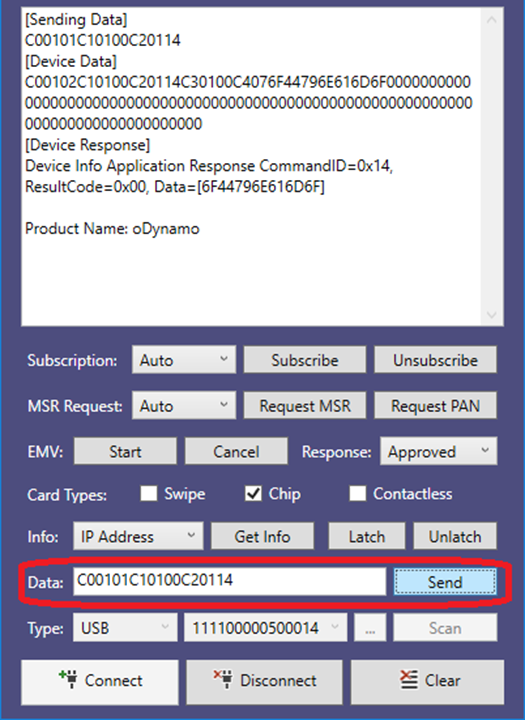
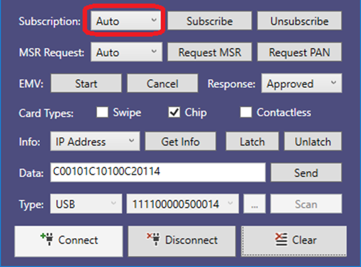
Initial Release
This document describes how to use the MagTek EMV Configuration application to verify the EMV configuration on a MagTek oDynamo and DynaWave connected to a host PC via USB interface.
This section will demonstrate how to use the MagTek EMV Configuration application on an oDynamo and DynaWave.
Connect the device to the host PC via USB cable.
Power cycle the device. Wait until the status LED is steady Green in color.
Press the Open button to connect to the device. The software will display the Serial Number and
Firmware Version.
Serial Number
This section will demonstrate how to view EMV tags.
After the device is already open, press on the EMV Tags select a Database, select a Slot, select a tag type from the list, and press theSend button
A list is displayed in columns of Tag, Length (decimal), Value (hexadecimal), and Description.
To view a subset from the result list, enter either a Tag, Value, or Description into the Filter input box. Below are examples of searching for the tag “dfdf16” and description “max size”.
To view specific tags, select a tag type without “All” in its description, enter a Tag value or list of values without spaces, then press the Send button. Below is example result of getting tags DFDF02 and DFDF16.
This section demonstrates how to verify the device against an EMVTag xml file. An EMVTag file contains an array of tags. Only tags listed in the EMVTag file are compared against the device.
Verify
Press the EMV Tags tab and press the Verify button.
Select the EMV tags file to be compared with the device, and press theOpen button.
Open
The status of the verification will be displayed. Each mismatched tag is shown as: Error Item [Tag] -> [ValueFromFile]
Example: Successful verification.
Example: Failed verification. Value in device is 00000080.
This section demonstrates how to view Certificate Authority Public Keys (CAPKs) on a device.
Press on the CA Public Key tab, select a Database, and press the Send button.
A list of CAPKs will be shown along with the status of the operation.
This section demonstrates how to verify the device against an EMVCAPK xml file. An EMVCAPK file contains an array of Certificate Authority Public Keys. Only CAPKs listed in the EMVCAPK file are compared against the device.
Press the CA Public Key tab and press the Verify button.
Select the EMVCAPK xml file to be compared with the device, and press the Open button.
The status of the verification will be displayed. Each mismatched RID is shown as: Error Item [RID] -> [ValueFromFile]
Example: Successful verification.
Example: Failed verification.
10
June 11, 2019
Table 1-1 in section 1.4 includes a list of connection types available for each device. The following subsections provide details developers will need to communicate with the device using each connection type.
How to Use Ethernet Connections (Ethernet Only)
When the device is connected to a network via a 10/100 Ethernet port, it will attempt to contact a DHCP server to acquire a dynamic IP address during power-up. See the network administrator to determine the IP address the DHCP server assigned to the device. After determining the IP address, use port 5000 to communicate with the device.
How to Send Commands Using the Network Connection
The messages exchanged between the host and the device on the TCP/IP connection do not require any wrappers or encoding: The binary data flowing through the connection is identical to the message format defined in section 2 Messages, Commands, Responses, and Notifications and in section 4 Command Set. A C0 at the beginning of a message’s usage table means that without any preparation other than binding to the port, the host begins sending the command by sending a single binary byte 0xC0.
For example, to send Command 0x00:0x10 - Get Product ID to the device over TCP/IP, the host should send a stream consisting of single binary byte 0xC0, followed by single binary byte 0x01, followed by single binary byte 0x01, followed by single binary byte 0xC1, and so on following the sequence in Table 4-1. The device will then send a response over the same connection according to the sequence in Table 4-2.
The messages exchanged between the host and the device on the RS-232 connection require a small wrapper and must be ASCII encoded hexadecimal (‘0’ through ‘F’ only). The message format is defined in section 2 Messages, Commands, Responses, and Notifications and in section 4 Command Set. ASCII encoding means when the device intends to send C0 at the beginning of a message’s usage table, it should send two ASCII bytes, where ‘C’ is ASCII 0x43 and ‘0’ is ASCII 0x30. When the device is using default settings, the host should send a line feed (0x0A) to signal the end of the message. The device’s responses and notifications will be wrapped and encoded the same way.
For example, to send Command 0x00:0x10 - Get Product ID to the device over the RS-232 connection, the host should send a stream consisting of ASCII ‘C’ (0x43), ASCII ‘0’ (0x30), ASCII ‘0’ (0x30), ASCII ‘1’ (0x31), ASCII ‘0’ (0x30), ASCII ‘1’ (0x31), ASCII ‘C’ (0x43), ASCII ‘1’ (0x31), and so on following the sequence in Table 4-1, then a line feed (0x0A). The device will then send a response over the same connection according to the sequence in Table 4-2, then a line feed (0x0A).
The devices only use TXD and RXD; hardware handshaking is not available. The default serial settings are 9600 bps, No parity, 8 data bits, and 1 stop bit.
The device can optionally be configured by the manufacturer to expect / transmit a Starting Byte and an ASCII CRC checksum in this order: <Starting Byte> <Message in ASCII> <CRC in ASCII> <Ending Byte>. The device’s default setting is “raw mode,” where the device only expects / transmits the Ending Byte, which is set to Line Feed (0x0A). Other popular choices when ordering a device may include Starting Byte=STX (0x02); Ending Byte=ETX (0x03) or CR (0x0D).
The device conforms to the USB specification revision 2.0, and is compatible with revision 1.1. It also conforms to the Human Interface Device (HID) class specification version 1.1, and communicates as a vendor-defined HID device. This document assumes the reader is familiar with USB HID class specifications, which are available at
Developers can easily create custom software to communicate with the device using any framework that can communicate with a USB port. For example, developers can use the standard Windows USB HID driver with Visual Basic or Visual C++. MagTek has developed demonstration software that communicates with the device via this method, and developers can use it to test the device and to provide a starting point for developing other software. Because the device’s USB implementation is operating system agnostic, the device can be used with other platforms as well, such as Linux. For more information, see the MagTek web site, or contact your reseller or MagTek Support Services.
The device is a full speed high-powered USB device that identifies itself with vendor ID 0x0801 and product ID 0x001B. The device does not draw power from the USB port, and does not support USB Suspend or remote wakeup.
USB HID devices send and receive data using reports. Each report can contain several sections, called usages, each of which has its own unique four-byte identifier. The two most significant bytes of a usage are called the usage page, and the least two significant bytes are called the usage ID. Vendor-defined usages must have a usage page in the range 0xFF00 - 0xFFFF, and it is common practice for related usage IDs to share the same usage page. For these reasons, all usages for this device uses vendor-defined usage page 0xFF20.
HID reports used by the host can be divided into three types:
Feature Reports, which can be further divided into Get types and Set types. The host exclusively uses this type of report to send messages to the device.
Input Reports are used by the device to send asynchronous responses or notifications to the host when a related feature report completes, or automatically when the device’s state changes. This is common when an operation depends on cardholder action.
Output Reports. Output reports are part of the USB HID standard, but are not used by this device.
The list of the device’s available reports and their structure is sent to the host in a report descriptor, usually just after the device is connected to the USB port. Generally the details of the report descriptor are abstracted by the developer’s HID API; however, should it become necessary to examine a report descriptor byte-by-byte, a full inventory of the report descriptor for these devices is provided in Table 3-1.
How to Send Commands Using USB HID
The general sequence the host should use to send a message to the device is as follows:
The host sends a Set Feature Report with Report ID 0x05, containing the command message in binary format (bytes) as data.
The device asynchronously sends an Input Report with Report ID 0x02, containing the defined response to the originating command in binary format (bytes) as data. Depending on the command, the response may or may not contain a Data Field Data Object (Tag C4 or E0).
The general sequence the device uses to send a message to the host is as follows:
The device’s state changes, a cardholder or operator takes action, or new information becomes available.
The device asynchronously sends an Input Report with Report ID 0x02, containing the notification message in binary format (bytes) as data.
April 8, 2019
Dear MagTek Customers,
In March 2019, NIST (National Institute of Standards and Technology) released a document entitled: “NIST Special Publication 800-131A Revision 2 – Transitioning the Use of Cryptographic Algorithms and Key Lengths1”. In that document, it states that the use of “Two-Key TDEA Encryption” has been listed as a “Disallowed” operational mode. This NIST document has raised concerns with our customers regarding the use of Two-Key TDEA Encryption within our products.
As a security leader, it is our intent to provide relevant information and guidance on this subject to our customers, and we can advise as follows:
At present time, “Two-Key TDEA Encryption” is currently the most widely used encryption method in the electronic payments and financial services sectors. It is used to protect both PIN and PAN payment data, and is used by most of the leading secure payment devices and payment networks deployed today.
As of this date there have been no successful attacks upon Two-Key TDEA Encryption that have resulted in the compromise of payment data encrypted under this mode. As such, Two-Key TDEA Encryption remains fully approved for use by both the ANSI X9 (American National Standards X9 - Financial Services) standards group and the PCI Security Standards Council.
MagTek customers who are currently using our products in the “Two-Key TDEA Encryption” mode can rest assured that the recent NIST announcements have no impact on security requirements within the Financial Services or Electronic Payments business sectors. As such, there is no need to make any changes to your MagTek products or encryption modes at this time.
It should be noted that the NIST recommendations only apply to Federal Agencies and their Information Systems. Commercial sector financial services are exempt from the NIST directives and are best served by following the ANSI X9 and PCI security standards organizations for recommendations on encryption requirements for payment data.
In regard to Two-Key TDEA Encryption for Transport Layer Security (TLS), PCI advised on this matter during a November 2017 blog entitled: “2”.
In that discussion, PCI acknowledges that the strength of Two-Key TDEA Encryption is under review and is no longer considered as “strong cryptography” by NIST. Further, PCI mentions that when NIST formally declares
MagTek, Inc. | 1710 Apollo Court | Seal Beach, CA 90740 | p. 562-546-6400 | f. 562-546-6301 |
Registered to ISO 9001:2015 © Copyright 2019 MagTek, Inc. PN D998200305 rev 10 4/19
Two-Key TDEA Encryption as “fully disallowed” it will no longer be considered “strong cryptography” by PCI SSC. Now that NIST has formally declared such (as of March 2019), the payment industry will need to await PCI’s further guidance on this subject.
In the interim, PCI has recommended that organizations begin planning their transition towards AES-128, yet acknowledges that due to legacy considerations this transition may take place over a long period of time.
Additionally, PCI recommends the use of several mitigation techniques to reduce risk. One of those measures is to “Change TDEA keys regularly…every 256 transactions or daily, whichever is more frequent”. In regard to this recommendation, MagTek can advise that our products utilize DUKPT (Derived Unique Key Per Transaction), a far more rigorous key management method. DUKPT ensures that a different key is generated for each and every transaction, taking PCI’s recommendation for frequent key changes to the maximum level.
Looking ahead, both the ANSI X9 and PCI Security Standards Council are establishing standards and transition paths towards the adoption of AES-128 as the successor to TDEA for encryption of payment data.
However, due to the proven security of TDEA, legacy concerns, and logistical considerations, it is anticipated that this transition will take place over the next 4-10 years. The earliest transition milestone will be the end of PCI support for TDEA PIN encryption using fixed-key management by Jan 1, 2023.
It is important to note that this milestone does not apply to the use of TDEA PIN encryption using DUKPT (Derived Unique Key Per Transaction) key management. As such, it is very likely that there will be a long transition period where both Two-Key TDEA DUKPT and AES128 DUKPT encryption methods will be used concurrently for the foreseeable future. (See table below for upcoming security milestones.)
As a security leader in the electronic payments industry, MagTek is moving forward with implementation of AES-128 DUKPT into our products and security services. In the meantime, we will continue to support Two-Key TDEA DUKPT encryption in our products for however long the payments industry requests it, and/or the relevant security standards support it.
As always, MagTek will continue to keep our customers informed on these matters and provide clear guidance as new security trends and requirements emerge.
If you have any further questions, please contact your MagTek Sales Representative or me and we will be happy to answer any questions you may have.
Sincerely,
Larry Meyers
Vice President, Qwantum Secure Media MagTek, Inc
1710 Apollo Court Seal Beach, CA 90740 562-546-6400
About MagTek
Founded in 1972, MagTek is a leading manufacturer of electronic systems for the reliable issuance, reading, transmission and security of cards, checks, PINs and identification documents. Leading with innovation and engineering excellence, MagTek is known for quality and dependability. Its products include secure card reader/authenticators, token generators, EMV contact, contactless and NFC reading devices, encrypting check scanners, PIN pads and distributed credential personalization systems for secure magstripe and EMV enabled cards. These products are used worldwide by financial institutions, retailers, and processors to provide secure and efficient payment and identification transactions.
Today, MagTek continues to innovate. Its MagneSafe™ Security Architecture leverages strong encryption, secure tokenization, dynamic card authentication, and device/host validation enabling users to assess the trustworthiness of credentials and terminals used for online identification, payment processing, and high- value electronic transactions.
MagTek is headquartered in Seal Beach, CA. For more information, please visit
Citations
1. Barker, Elaine and Roginsky, Allen; March 21, 2019; NIST Special Publication (SP) 800-131A Revision 2; “Transitioning the Use of Cryptographic Algorithms and Key Lengths”
2 and and “PCI SSC Cryptography Expert on Triple DEA”; link:
This section provides information and guidelines for designing the mechanical aspects of a solution that incorporates oDynamo. MagTek strongly recommends vetting and testing solution designs before finalizing and deploying them, to make sure the design meets all requirements (e.g., functional, legal, security, certification, safety, and so on).
When designing the mechanical portions of a solution that incorporates oDynamo, consider the following:
MagTek offers a range of high-performance, low-cost Application Specific Integrated Circuits (ASICs) designed for OEM developers building magnetic stripe card reading systems. These three-channel fully integrated decoder chips significantly simplify the card-reader to microcontroller interface. The family includes the Triple-Track Delta ASIC, a proven solution widely used to read three tracks of card data for financial and retail applications. The next-generation Qwantum ASIC adds support for the Serial Peripheral Interface (SPI), integrated AES-256 encryption, and much lower power demand, making it ideal for advanced, battery-powered devices requiring both card data decoding and Qwantum security features. The ASICs are available in ultra-compact packages requiring minimal external components, feature a data buffer with Shift-Out protocol, high noise immunity, high performance decoding, low voltage operation, and a wide operational temperature range supporting a broad spectrum of card swipe speeds. The official MagTek ASICs support page is a central hub containing all the resources you'll need. There you can find the 2024 product catalog, the OEM Components brochure offering an overview of ASICs, Heads, Head Assemblies, and Rails, programmer's manuals including an application note for character conversion, and technical reference manuals such as the Magnetic Card Reader Design Kit and specifications for the Triple-Track Delta ASIC with Shift-Out (3 Volt and RoHS Compliant versions).
Report Size (8)
75 08
Logical Minimum (0)
15 00
Logical Maximum (255)
26 FF 00
Report ID (5)
85 05
Usage (Vendor-Defined 5)
09 05
Report Count (63)
95 3F
Feature (Data,Var,Abs,NWrp,Lin,Pref,NNul,NVol,Buf)
B2 02 01
Report ID (2)
85 02
Usage (Vendor-Defined 32)
09 20
Report Count (63)
95 3F
Input (Data,Var,Abs,NWrp,Lin,Pref,NNul,Buf)
82 02 01
Report ID (3)
85 03
Usage (Vendor-Defined 33)
09 21
Report Count (5)
95 05
Output (Data,Var,Abs,NWrp,Lin,Pref,NNul,NVol,Bit)
91 02
End Collection
C0
Item Tag (Value)
Raw Data
Usage Page (Vendor-Defined 33)
06 20 FF
Usage (Vendor-Defined 1)
09 01
Collection (Application)
A1 01
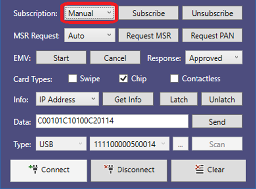
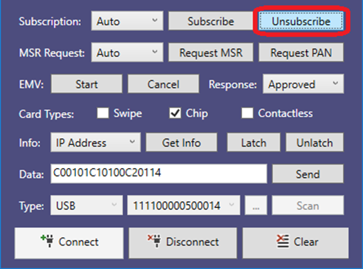
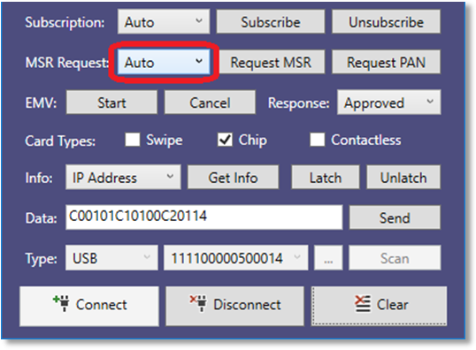
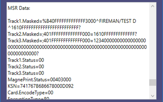
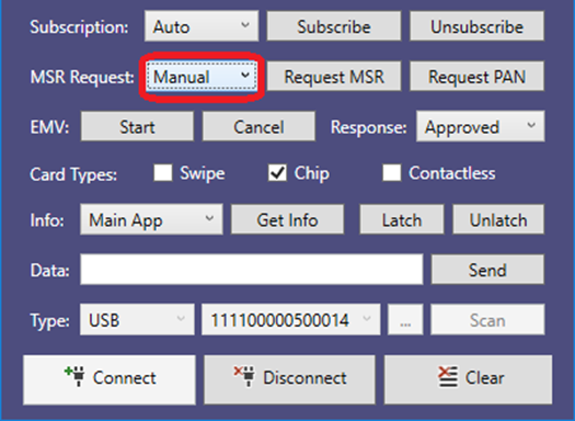
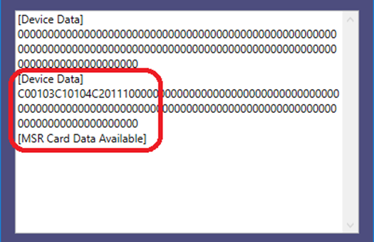
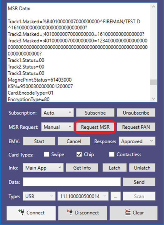
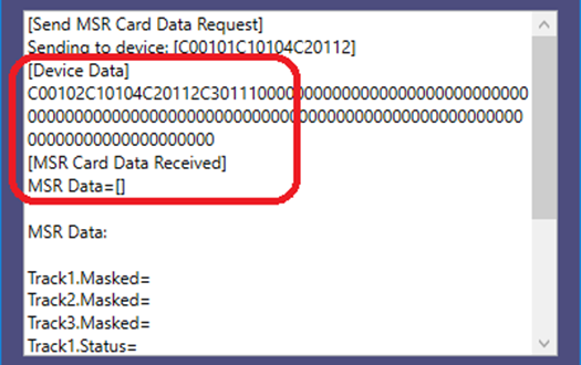
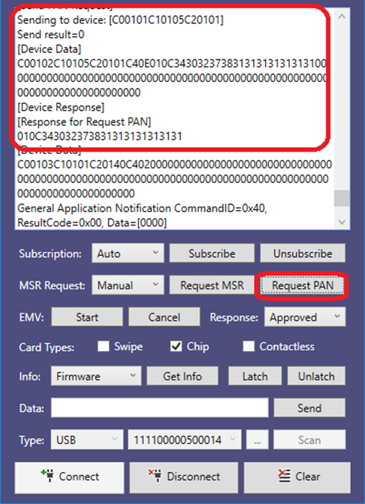
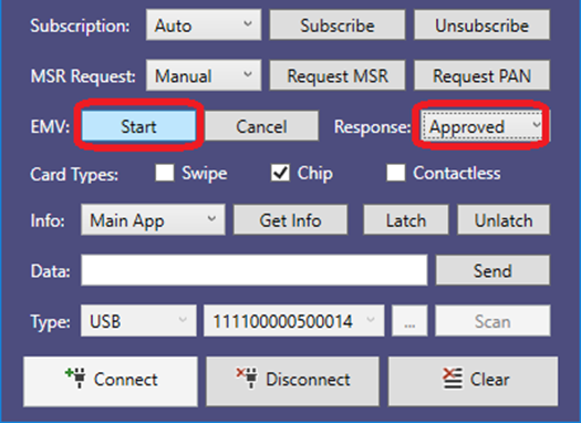
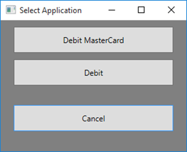
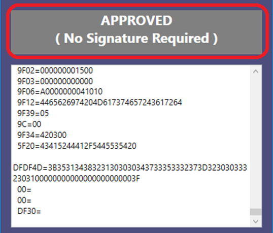
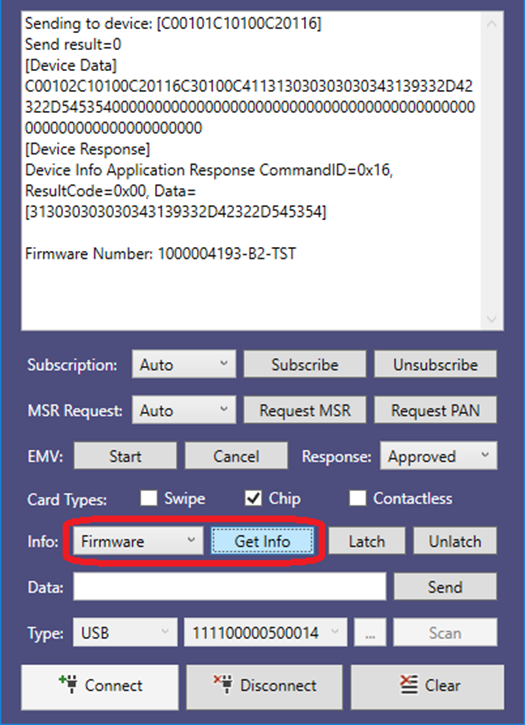
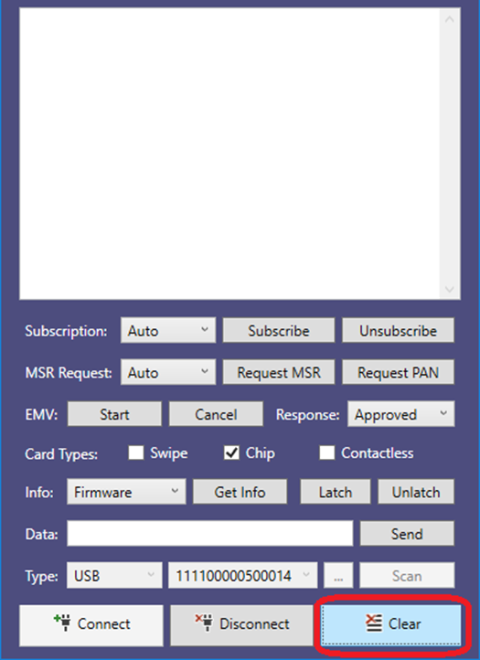
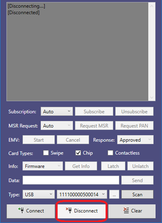
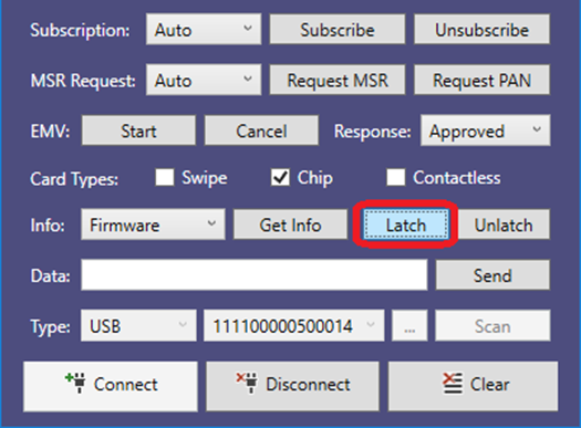
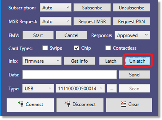
PCI PIN
All hosts must support ISO PIN Block Format 4 (AES)
DECRYPTION
Jan 1, 2023
PCI PIN
All hosts must support ISO PIN Block Format 4 (AES)
DECRYPTION & ENCRYPTION
Jan 1, 2025
Security
Entity
Requirement
Effective Date
VISA PCI PIN
Sunset data for SINGLE DES PIN encryption
(applies to fuel dispenser environments POS only)
Oct 1, 2020
PCI PIN
FIXED Key for TDEA PIN encryption in POI devices and
Host-to-Host connections is disallowed
Jan 1, 2023
Review section 1.6 About oDynamo Components for an overall introduction to the device’s physical features and what they are called.
Review Appendix A Technical Specifications.
See section 3.2 Dimensions for overall device dimensions.
Design the solution enclosure front panel. Information about fitting the device into a panel cutout are in section 3.4 Panel Cutout.
Determine how the device will be mounted. See section 3.5 Mounting for details. Coordinate with the electrical design team to make sure the panel design, mounting hardware, and solution-specific installation instructions meet electrical requirements.
Coordinate with the electrical design team to plan cable routing and fastening. See section 3.6 Cabling for details.
Consider additional factors that do not fit these categories. See section 3.7 Miscellaneous Considerations.
Review safe handling practices in section 1.9 Handling to make sure the logistical aspects of the solution design meet the device’s handling requirements.
Review recommended installation practices in section 4 Installation. The steps provided in that section depend on the solution design team to customize the steps or fill in solution-specific details before distribution to installation technicians.
Review section 6 Maintenance. When installed in the solution-specific enclosure, the maintenance procedures may require modifications, or the solution may require additional maintenance not covered in the general guidelines provided here.
Review any additional requirements from other agencies, such as PCI certification requirements, building codes, and so on, which may introduce additional constraints to the design.
Overall dimensions of the device are shown in Figure 3-1. On request, MagTek can provide a 3D model of the device’s envelope to assist with the mechanical portion of solution design. MagTek strongly recommends building and testing prototypes with actual devices before finalizing the solution design.
Figure 3-1 - oDynamo Mechanical Dimensions in Inches [mm]
For optimum results, MagTek recommends orienting the device for horizontal card insertion (see Figure 3-2). Although it is possible to mount the device in vertical orientation, doing so may lead to impaired device function caused by the potential for increased accumulation of debris. Maintenance planning should take this into consideration.
Figure 3-2 - oDynamo Mounting Orientation
The device must be installed such that cardholders have a full, unobstructed view of the housing around the card insertion slot opening (“entry zone”) prior to insertion. This is to allow cardholders to easily detect suspicious objects in or around the card slot entry, such as bugs / skimmers / tapping mechanisms, and their wires or antennas. Installation height is one factor in meeting this requirement: Assuming the solution design does not add features that obstruct the view of the slot, choosing the installation height involves making sure the nominal inspection position has a view of the device that is no greater than 55° above the horizontal plane of the device (measured from the plastic body), which provides a view similar to Figure 3-3. If the solution mounts the device at a downward pitch, subtract the pitch angle from the 55° before calculating. For example, if the nominal inspection position is 12” away from the device and 60” above the ground, and the device is mounted at 0° pitch, the device’s slot must be mounted no higher than 60”-(12”)tan(55°-0°)=43”.
Figure 3-3 - View from 55 Degree Angle Above Device Horizontal
The device incorporates a number of drain holes, shown in Figure 3-4. Drainage requirements are as follows:
The drain holes must not be obstructed.
The device must be oriented with the drain holes on the bottom.
The enclosure must pitch the device’s face between 0 degrees (level) and 30 degrees downward. It must not pitch the device’s face upward (see Figure 3-5, 0° ≤ θ ≤ 30°).
Figure 3-4 - oDynamo Drain Holes
Figure 3-5 - oDynamo Mounting Pitch
The device is designed to be integrated into a solution design that includes an enclosure to secure the device and protect it from the elements. This section provides guidelines for creating a cutout in the enclosure’s front panel that accommodates the device.
The device’s installation face and gasket provide a seal against the elements:
The enclosure panel must be flat and rigid to produce a solid seal with the gasket and to provide security against tampering.
The solution’s enclosure must include a cutout that is sized to expose the device’s bezel while still squeezing the gasket.
The enclosure must protect the device from unauthorized tampering.
The enclosure must protect the device from the elements. The device is designed for ingress protection from the gasket forward, but the rear of the device behind the gasket must be protected.
The device is sized for Compact Door Module hole patterns as specified by the European Vending Association (EVA) Electronic Payment Specification for Unattended Point Of Sale (UPOS), EVA EPS 1.1. Reference dimensions for the cutout in the solution enclosure, including the location of either screw holes or threaded studs, are shown in Figure 3-6; the outside dimensions of the sample cutout plate represent absolute minimum required clearances for the cutout’s overall placement in the enclosure. Detailed dimensions of the device’s installation face are shown in Figure 3-7.
Figure 3-6 - oDynamo Panel Cutout Dimensions in Inches [mm]
Figure 3-7 - oDynamo Mounting Face Dimensions in Inches [mm]
The solution design’s mounting hardware and torque specifications must apply adequate force to create a water-tight seal between the enclosure and the gasket. For example, for M4 nuts/bolts, the torque may be in the range of 0.7 N-m (6 to 7 in-lbs.).
The device is designed to be mounted either onto screws (see Figure 3-9) or onto threaded studs permanently attached to the enclosure (see Figure 3-8), and nuts. The maximum shaft size for screws or studs is #10 or M5. Make sure mounting hardware in contact with the mounting holes conforms to the grounding requirements in section 2 Electrical Integration.
Figure 3-8 - oDynamo Threaded Stud / Nut Mounting
Figure 3-9 - oDynamo Screw/Nut Mounting
This section provides information about mechanical integration of cables into a solution design. For details about electrical aspects of integrating the device, see section 2 Electrical Integration.
The device incorporates cable tie mounts (see Figure 1-1) that can be used with cable ties (not included) to implement cable strain relief. See Figure 3-10 for an example of tying down cables.
Figure 3-10 - Cable Strain Relief
The enclosure should include adequate clearance for installation and maintenance personnel to connect and disconnect all cables. If the solution uses the device’s cable tie mounts for strain relief, it should provide additional clearance to remove and re-fasten the cable ties. It should also provide support for the device when cables are being connected and disconnected.
Installation technicians will need to be provided detailed instructions for installing the cabling. For some basic guidelines, see section 4 Installation.
The device includes a label well (see Figure 1-1) around the General Status LED that can accommodate solution-branded labels. Labels should incorporate a cutout so they do not obstruct the LED.
The device operates on low power, so no special cooling should be necessary. However, there must be adequate clearance around the vent holes in the top of the device’s body for heat to escape (see Figure 3-11), and the enclosure must not be an isolated thermal system that traps indefinite amounts of heat.
This document describes how to use oDynamo securely. Using the device in any way other than the approved methods described in this document invalidates the PCI PTS approval of the device.
Not following the guidelines in this section could damage the device, render it inoperable, and/or violate the conditions of the warranty.
Need Help?
For additional support, please contact MagTek Support:
Technical Support:
📧 Email: support@magtek.com
📞 Phone: 1-562-546-6800 (US)
🕐 Hours: Monday-Friday, 5:30 AM - 5:00 PM PST
Online Resources:
🌐 Support Portal: developer.magtek.com
Documentation Feedback:
Help us improve this documentation!
oDynamo is a PCI PTS 5.x, SRED Certified hybrid insertion reader. oDynamo’s enclosure and its associated electronics have been designed to form a Tamper Resistant Security Module (TRSM). The covers are securely attached and incorporate sensing circuits to detect if any attempt is made to open the device. Internal spaces within the device have been minimized to reduce the possibility
of unauthorized modifications. Any attempt to penetrate or modify oDynamo electronically will cause the device to permanently erase its stored encryption keys, after which oDynamo will cease to function. Inspect the following areas of the device for tampering.
Carefully inspect the form factor. Make certain there are no additional electronics, wires or forms added to the device. Check the overall form factor for signs of attempted entry.
Look for any hidden and additional wires in crevasses, seams, and exterior surface. Check there are no additional wires on the device.
The device’s installation face includes a gasket. Do not remove the gasket.
The front face metal bezel is one die-cast piece. Inspect for any modification or hidden wires protruding from the card slot or drain holes.
The device includes a label well around the General Status LED. MagTek is default label.
Apply power to the device, LED should be solid GREEN. Apply power to the device for 60 seconds. If the LED shows any red, a tamper event has occurred.
The product label is located on the back of the device. Check PN, SN and HW number. Serial Number matches serial number on boot-up.
Look for any hidden and additional wires in crevasses, seams and exterior surface of the device.
Check tampering of 6 screws. DO NOT REMOVE THE SCREWS.
PRIOR TO INSTALLATION Inspect for objects or wires in the vent holes.
The card insertion slot is a smooth, unobstructed path. Insert an embossed card into the device to check for any signs of obstruction inside. Other than the magnetic head that reads magnetic stripes and contact points that read chips there are no electronics, objects, or wires on the path.
Unauthorized removal of switches will disable the device. Exercise the two (2) dismount switches by pressing them. They should return to the original position upon release of finger pressure.
Inspect individual connection ports
RS-232 and Power Port
USB Host Port
USB Device Port
Ethernet Port
Check tampering of 4 screws. DO NOT REMOVE THE SCREWS.
PRIOR TO INSTALLATION Inspect for objects or wires in the vent holes.
The card insertion slot is a smooth, unobstructed path. Insert an embossed card into the device to check for any signs of obstruction inside. Other than the magnetic head that reads magnetic stripes and contact points that read chips there are no electronics, objects, or wires on the path.
Unauthorized removal of switches will disable the device. Exercise the two (2) dismount switches by pressing them. They should return to the original position upon release of finger pressure.
Inspect where the seams come together to ensure there are no extraneous wires.
Inspect crevasses to ensure there are no extraneous wires.
Inspect the 4x drain holes below the bezel nose (plus the 1x drain hole to the left side of the bezel nose). There are no electronics, objects or wires coming from the drain holes.
Inspect where the seams come together to make ensure are no extraneous wires.
Inspect crevasses to make certain there are no extraneous wires.
Carefully inspect the form factor. Ensure there are no additional electronics, wires, or forms added to the device.
Periodically inspect the following items:
Metal Bezel
Card Slot
When servicing behind cabinet/door (terminal) inspect device for external wires, or foreign objects not included in the solution design. For proper installation, refer to your solution design documentation.
Observe front face of the metal bezel and inspect for any modification or hidden wires.
Look for any hidden and additional wires. No additional wires should be coming out of the holes.
Check all views of the device and compare to photos.
It is helpful to do the following for your device inspection audit.
Have a list of the device sand details listed on the asset tag.
Take photos of the front, back, and sides of each device.
Check device Part numbers, serial numbers and IDs and check physical connections. Report any suspected signs of tampering immediately.
How to find oDynamo on PCI web site https://www.pcisecuritystandards.org/assessors_and_solutions/pin_ transaction_devices.
Search for MagTek and find the product name, oDynamo, on the web page. Compare the Hardware # and Firmware #.
Periodically inspect the following items while installed: Exterior surface/metal bezel
Card slot
Five (5) drain holes
Form factor
Crevasses
Inspect the following additional items during service:
Crevasses
Screws
Ventilation holes
Connection ports
For all mDynamo module documentation, including programmer’s manuals, the technical reference manual, software/SDKs, and warranty info, please visit the official mDynamo module Support Page:
Need Help?
For additional support, please contact MagTek Support:
Technical Support:
📧 Email:
This class is a subclass of MTCMSMessage. This class instantiates an MTCMSMessages instance with MessageID value set to the Request message type.
This constructor method builds and initializes an MTCMSRequestMessage instance with the provided values.
public void MTCMSRequestMessage(int applicationID, int commandID, int dataTag, byte[] data)Parameters:
Parameter
Description
applicationID
Return Value: None
ODynamo SCRA reads magnetic stripe cards and EMV chip cards and is PCI compliant. The packaging has been designed to be tamper resistant and tamper evident. The packaging closure uses security tape. Any attempt to open the package would show signs of tampering. This document reviews how to detect tamper evidence in a single and multi-pack package.
For all MagneSafe IntelliHead documentation, including programmer’s manuals, the technical reference manual, software/SDKs, and warranty info, please visit the officialMagneSafe IntelliHead Support Page:
ApplicationID value
commandID
CommandID value
dataTag
Data Tag value
data
Data value
📞 Phone: 1-562-546-6800 (US)
🕐 Hours: Monday-Friday, 5:30 AM - 5:00 PM PST
Online Resources:
🌐 Support Portal: developer.magtek.com
Documentation Feedback:
Help us improve this documentation! feedback@magtek.com
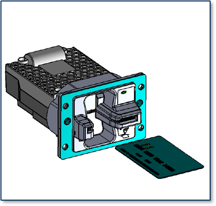

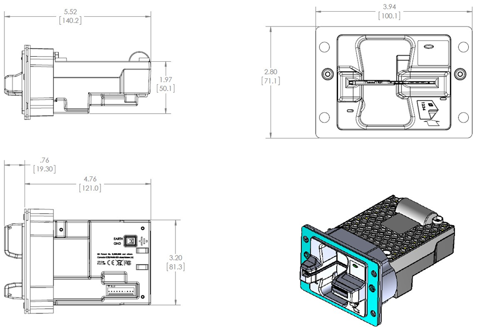
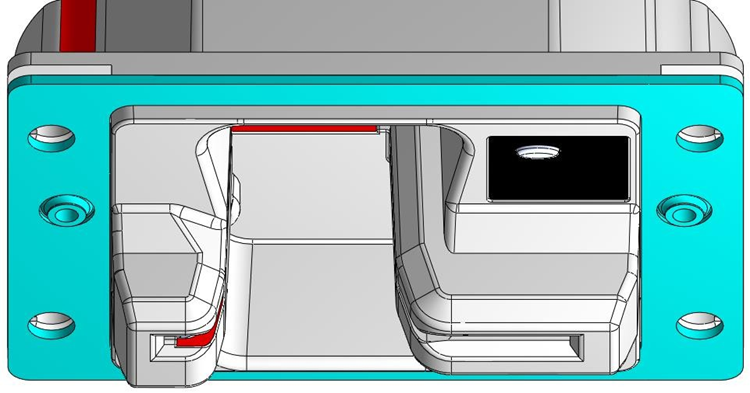
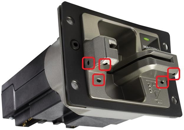
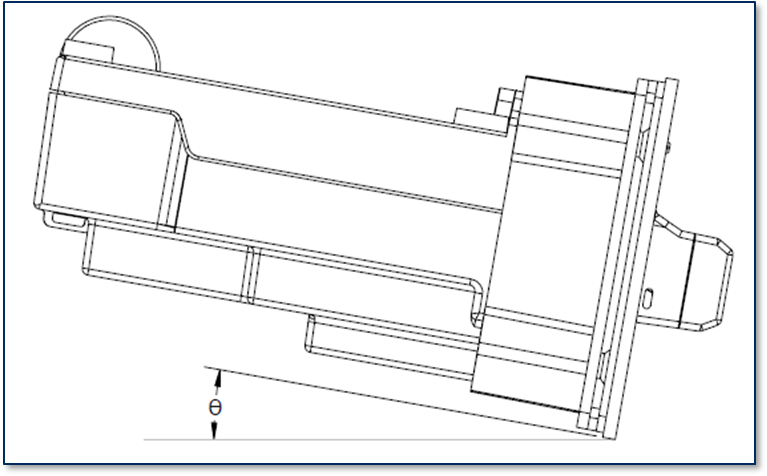
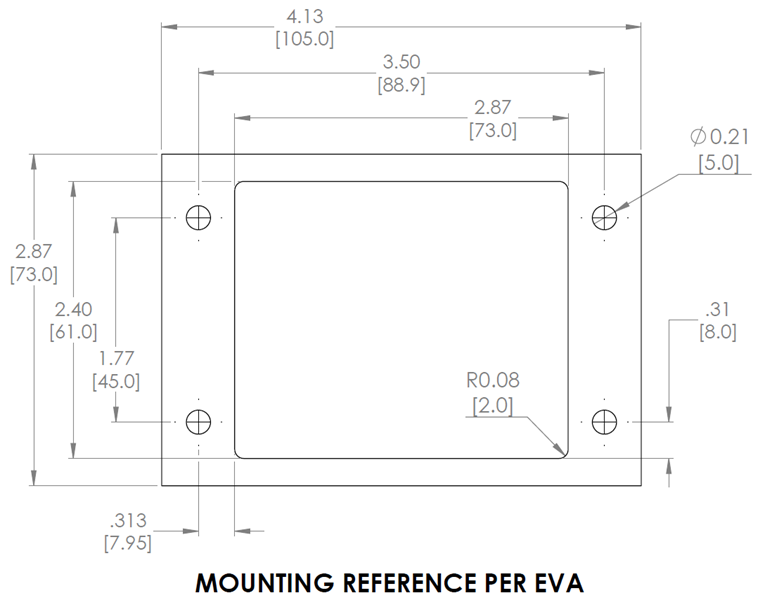
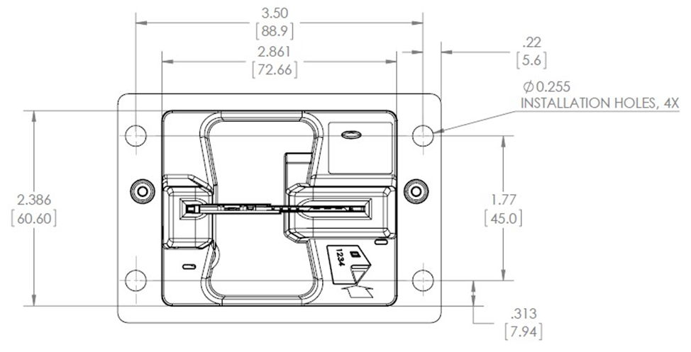
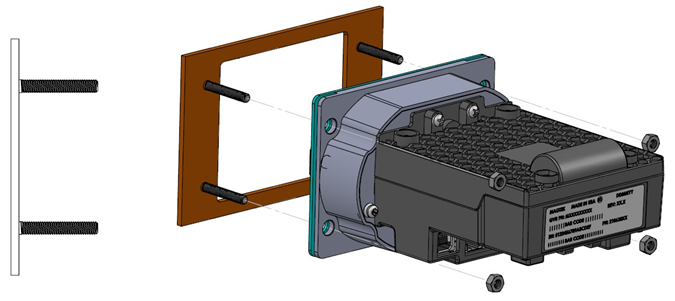
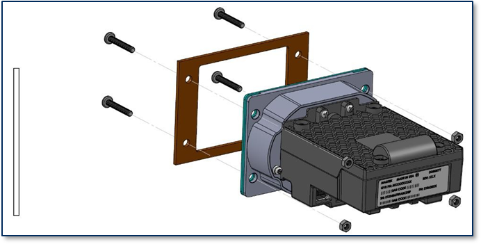
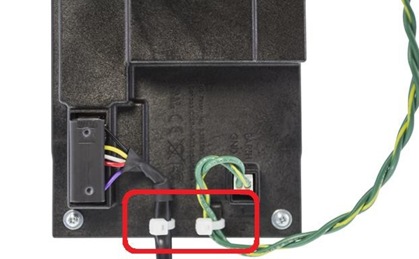
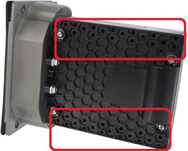
Alternative Earth Grounding Port
Screws
Seams parting lines
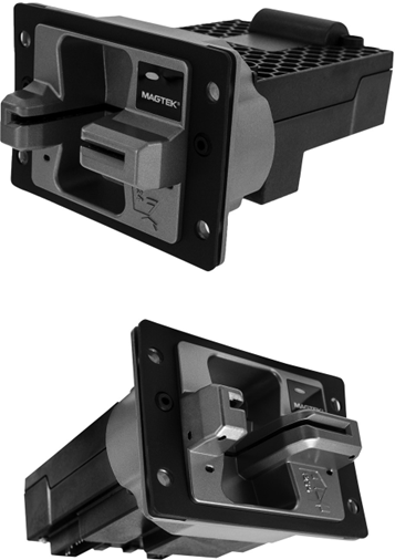
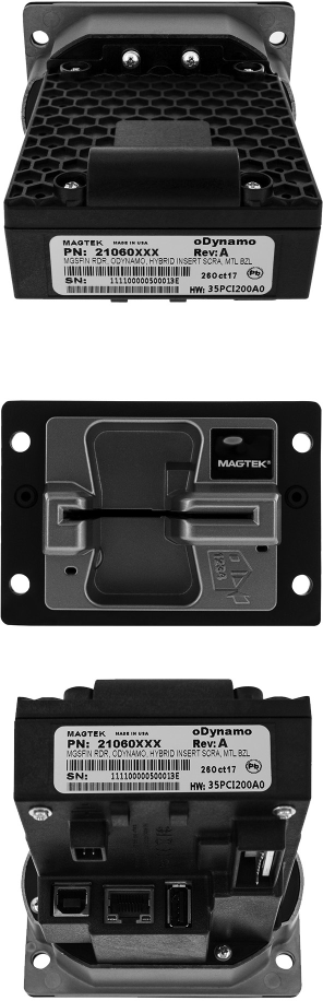
Does the box appear to be torn or cut?
Is there any damage to the box?
Are there any changes to the printing or labeling?
Inside the package
Are the components placed in the box as pictured in this document?
Security Tape
Is the tape missing? Devices are always shipped with security tape. Tape is red. The tape should only be located as pictured.
Do you see the words "OPENED" or "VOID" where the tape is supposed to be?
After removal of the security tape, it will leave red ink glued to the box: inverse OPENED and VOID text.
Has the tape been cut? Has it been replaced? Check to make certain the tape has not been cut and that new clear tape has not been placed over the existing security tape.
Is there any evidence of red ink? Does the front edge show any residual red ink, or scratch marks from an attempt to remove the residual security tape ink.
Installation site inspection
If yes, then tampering has occurred
If no, then continue inspection
Sealed plastic enclosure
Does the device appear to have any physical forced entry points?
Check the overall form factor for signs of attempted entry.
SN label and security tape are applied to top of package.
Security tape is applied to bottom of package.
Packing Lot Label is applied to side of package.
Inside of package holds device inspection document.
Security tape secures the package together. The package itself is a brown box as pictured below with fitted foam.
Check the overall form factor for signs of attempted entry.
Security tape goes across center package seam. Clear packaging tape is across package ends seams.
Security tape is applied across the bottom package seam.
Package front has a MagTek logo and UN 3091 battery warning emblem.
Package back has MagTek logo and storage notice.
Security tape is applied across the top and bottom of the package, to not overlap at the sides.
Security tape is applied across the top and bottom of the package, to not overlap at the sides.
Security tape is red and applied across center seam of package.
When tape is peeled back, “OPENED” warning pulls from tape and adheres to package. There is clear evidence of attempts to remove tape. Check seams have not been cut and re-taped.
This lists the serial numbers of the devices packed in the shipment.
On one side, the serial number list label and LOT label is applied.
Inside the package is a pad to secure the devices, pictured below.
After removing the pad, there are partitions that separate the devices from one another.
Devices additionally have MAGTEK security tape holding the static shield bag in place.
On the end of the static shield bag is the device serial number. Compare this with the serial list label on the outside of the package.
A view of the partition with no devices. The partitions are designed to hold a maximum of 10 devices.
To check for PCI Validation check the Hardware and Firmware ID. Hardware ID is printed on the label. The Firmware ID is accessible via the device and displayed on the screen. Go to the PCI compliance web page, compare the Hardware ID and Firmware ID: https://listings.pcisecuritystandards.org/popups/pts_device.
Package inspection upon receipt
If yes, then tampering has occurred
If no, then continue inspection
Cardboard box - Top, Bottom, Sides
If the security switches have been tripped, the oDynamo cannot be repaired in the field. It must go back to the factory for repair. Follow RMA procedures. Report all signs of tampering as per standard protocol.
Need Help?
For additional support, please contact MagTek Support:
Technical Support:
📧 Email: support@magtek.com
📞 Phone: 1-562-546-6800 (US)
🕐 Hours: Monday-Friday, 5:30 AM - 5:00 PM PST
Online Resources:
🌐 Support Portal: developer.magtek.com
Documentation Feedback:
Help us improve this documentation!
This document provides guidelines and technical information for designing solutions that integrate oDynamo, MagTek’s manual insertion Secure Card Reader Authenticator (SCRA) for OEM solutions.
oDynamo is a secure insertion card reader that is built to be durable and flexible. oDynamo allows for fast, reliable, and secure reading of magnetic stripe and chip card data from cards that meet the ISO 7810, 7811, and 7816 specifications. The slot and chassis are designed so cardholder-facing elements are impervious to liquid and other harsh environmental elements, making it an ideal solution for gas pumps, ATMs, and vending machines. Ultimate system design flexibility makes it ideal for a variety of unattended payment terminals.
oDynamo withstands a wide range of operational conditions and supports multiple communication protocols, and offers a USB connection, an Ethernet connection, and a serial connection.
oDynamo is made to work in harsh environmental conditions and delivers reliability of 500 thousand magnetic stripe swipes and 500 thousand chip inserts. The device is designed to be integrated into a solution that provides an enclosure. The device has been tested by an FCC lab for Class B radiated susceptibility and has no special shielding requirements.
oDynamo is secured by the MagneSafe™ Security Architecture (MSA), providing immediate encryption of card data using Triple DEA encryption with Derived Unique Key Per Transaction (DUKPT) key management. Additionally, oDynamo provides advanced MagnePrint® Card Authentication, which enables authorizing parties to detect and stop counterfeit card fraud in real-time. The firmware and the encryption keys are securely downloaded to the reader eliminating the chance of tampering.
The card latch feature allows the card to be securely held within the reader during the entire transaction process, and reduces the possibility of unwanted human intervention during card read operations. Power-fail card latch release and manual override features are available to ensure that a cardholder’s card can be easily retrieved under any conditions.
Cardholder-facing elements impervious to Liquid
Supports Multiple Protocols
Card Seated Sensor
ESD Protection: ±4kV contact discharge / ±8kV air discharge
In this document, oDynamo is referred to as the device. It is designed to be connected to a host, which is a piece of general-purpose electronic equipment which can send commands and data to, and receive data from, the device. Host types include PC computers/laptops, tablets, and smartphones. Generally, the host must have software installed that communicates with the device and is capable of processing transactions. The combination of device(s), host(s), software, firmware, configuration settings, physical mounting and environment, user experience, and documentation is referred to as the solution. During a transaction, the host and its software interact with the operator, such as a cashier or bank teller, while the device interacts with the cardholder.
A smooth deployment of a solution that integrates oDynamo requires some up-front planning and decision-making:
Determine the overall functional requirements and desired user experience of the solution oDynamo will be integrated into.
Determine what documentation and training will be required from solution design through testing and field deployment.
Determine what type of host oDynamo will connect to, and what connection type it will use. The host can be a computer with a USB port, serial (RS-232) port, or Ethernet port. When planning, include any additional support or devices required by the host and its connection, such as physical locations, mounting, and power connections.
From device delivery through assembly, shipping, installation, usage, and maintenance, the device must not be exposed to conditions outside the ratings in Appendix A Technical Specifications.
If the device is exposed to cold temperatures, adjust it to warmer temperatures gradually to avoid condensation, which can interfere with the operation of the device or cause permanent damage.
Upon receiving the device, inspect it according to D998200235 oDynamo Device Inspection procedure included in the box to make sure it originated from an authentic source and has not been tampered with.
Do not drop or shake the device.
The device should be transported/stored inside an anti-static bag at all times.
Before removing the device from the package, remove any static charge from your body by touching an earth-grounded metal surface.
Avoid touching the exposed pins on the connectors when handling the device.
For information about ongoing maintenance of the device, such as cleaning, see section 6 Maintenance.
This page provides documentation for MagTek OEM components, including mechanical drawings, developer guides, and setup instructions to help you integrate secure transaction components (secure magnetic read heads, decoder chips, EMV chip modules, USB swipe readers, card guide rails, and shift-out heads) directly into your custom hardware designs for payment terminals, kiosks, and unattended retail and banking applications.
Product
Description
The first magnetic sensing, media-validating, tamper-resistant security module that reads three tracks of magnetic stripe data, encrypts it inside the head using 3DES and DUKPT, and authenticates cards with MagnePrint technology to help OEMs meet stringent PCI security requirements.
Copyright © 2006 - 2021 MagTek, Inc. Printed in the United States of America
INFORMATION IN THIS PUBLICATION IS SUBJECT TO CHANGE WITHOUT NOTICE AND MAY CONTAIN TECHNICAL INACCURACIES OR GRAPHICAL DISCREPANCIES. CHANGES OR IMPROVEMENTS MADE TO THIS PRODUCT WILL BE UPDATED IN THE NEXT PUBLICATION RELEASE. NO PART OF THIS DOCUMENT MAY BE REPRODUCED OR TRANSMITTED IN ANY FORM OR BY ANY MEANS, ELECTRONIC OR MECHANICAL, FOR ANY PURPOSE, WITHOUT THE EXPRESS WRITTEN PERMISSION OF MAGTEK, INC.
MagTek® is a registered trademark of MagTek, Inc. MagnePrint® is a registered trademark of MagTek, Inc. MagneSafe® is a registered trademark of MagTek, Inc. Magensa™ is a trademark of MagTek, Inc.
MagTek highly recommends using the 32-bit version of Java when using the PCI PED Java applet, regardless of whether you are using a 32-bit or 64-bit version of Windows.
Uninstall any existing instances of the 64-bit Java Runtime Environment (JRE) or Java Development Kit (JDK). Leaving them installed can cause runtime failures, as the library may fail to load.
Download and install the latest version of the 32-bit Java Development Kit (JDK).
This page provides comprehensive documentation for the oDynamo hybrid insertion secure card reader authenticator (SCRA), including programmer's manuals, quick installation guides, EMV configuration tools, compliance documentation, downloadable software, and marketing materials to support integration into unattended OEM solutions.
Are there any breaks in the sealed plastic enclosure?
Tripped device
If there is forced entry, the security switches built into the electronics will be tripped. If they are tripped the sensitive data such as encryption keys and certificates are cleared as part of security measures mandated by PCI, and the oDynamo will be non-responsive with a blank display. Is the device non-responsive?
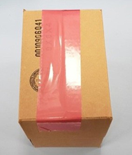
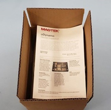
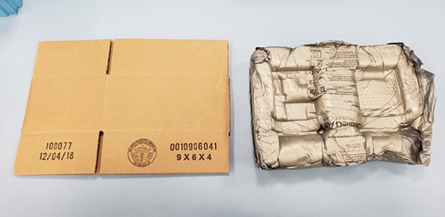









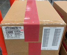

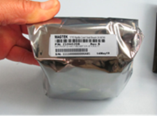
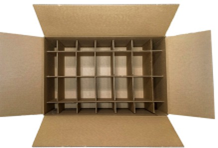
EMVCo ESD Protection ±12kV air discharge
Card Latch
Anti-Tamper Security Features
Secure Download and Authentication of Firmware and of Encryption Keys
Determine what software will be installed on the host and how it will be configured. Software can include operating system, transaction processing software, security software, and so on. Include any additional support required by the software, such as network connections.
Determine how oDynamo should be configured, and specify that when you order devices. MagTek or your reseller can advise. For deep detail about configuration options and how they affect device behavior, see D998200162 ODYNAMO PROGRAMMER'S MANUAL (COMMANDS).
Determine how the solution design will integrate oDynamo electrically (see section 2 Electrical Integration for details).
Determine how the solution design will integrate oDynamo mechanically (see section 3 Mechanical Integration for details).
Develop an installation procedure. Basic device installation steps are provided in section 4 Installation, but installing technicians will need solution-specific materials. For example, technicians may be supported by incorporating a Maintenance Mode into the host software for configuration, updates, and diagnostic tests.
Determine how the solution will be tested and, if appropriate, how it will be certified.
Determine how the solution will be maintained. See section 6 Maintenance for guidance on maintaining the oDynamo portion of the solution.
Determine how the solution will be regularly inspected. MagTek provides D998200235 oDynamo Device Inspection with each device, but proper inspection will require additional solution-specific training, instructions, and visual references for inspecting the entire solution for tampering, unauthorized added components such as eavesdropping or skimming devices, and so on.
This document describes how to use oDynamo securely. Using the device in any way other than the approved methods described in this document invalidates the PCI PTS approval of the device.
Proper handling of the device throughout delivery, assembly, shipping, installation, usage, and maintenance is very important. Not following the guidelines in this document could damage the device, render it inoperable, and/or violate the conditions of the warranty.
The device does not contain any user-serviceable parts. Removing ANY screw, or otherwise attempting to disassemble or modify the device, is very likely to trigger tamper protection and render the device inoperable.
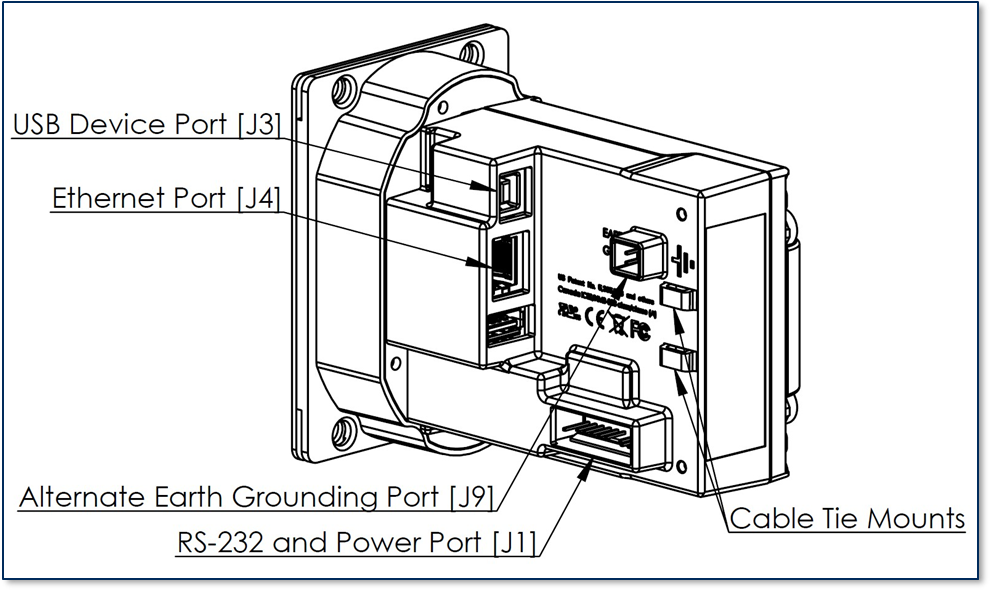
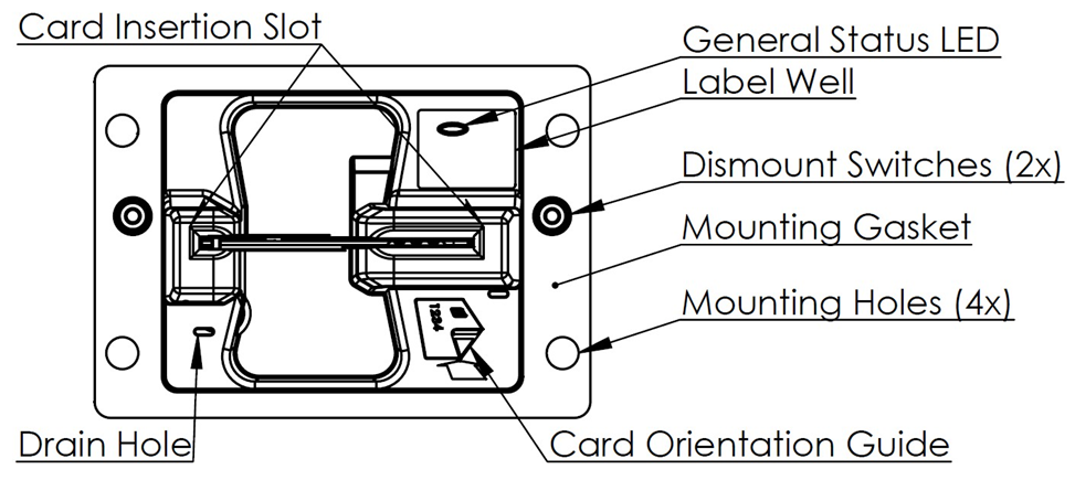
MasterCard® is a registered trademark of MasterCard International Incorporated.
ANSI®, the ANSI logo, and numerous other identifiers containing "ANSI" are registered trademarks, service marks, and accreditation marks of the American National Standards Institute (ANSI).
ISO® is a registered trademark of the International Organization for Standardization.
PCI Security Standards Council® is a registered trademark of the PCI Security Standards Council, LLC. EMVCo™ and EMV™ are trademarks of EMVCo and its licensors.
UL™ and the UL logo are trademarks of UL LLC.
All other system names and product names are the property of their respective owners.
Table 0-1 - Revisions
Rev Number
Date
Notes
10
July 31, 2017
Initial release
20
Jan 11, 2018
LIMITED WARRANTY
MagTek warrants that the products sold pursuant to this Agreement will perform in accordance with MagTek’s published specifications. This warranty shall be provided only for a period of one year from the date of the shipment of the product from MagTek (the “Warranty Period”). This warranty shall apply only to the “Buyer” (the original purchaser, unless that entity resells the product as authorized by MagTek, in which event this warranty shall apply only to the first repurchaser).
During the Warranty Period, should this product fail to conform to MagTek’s specifications, MagTek will, at its option, repair or replace this product at no additional charge except as set forth below. Repair parts and replacement products will be furnished on an exchange basis and will be either reconditioned or new. All replaced parts and products become the property of MagTek. This limited warranty does not include service to repair damage to the product resulting from accident, disaster, unreasonable use, misuse, abuse, negligence, or modification of the product not authorized by MagTek. MagTek reserves the right to examine the alleged defective goods to determine whether the warranty is applicable.
Without limiting the generality of the foregoing, MagTek specifically disclaims any liability or warranty for goods resold in other than MagTek’s original packages, and for goods modified, altered, or treated without authorization by MagTek.
Service may be obtained by delivering the product during the warranty period to MagTek (1710 Apollo Court, Seal Beach, CA 90740). If this product is delivered by mail or by an equivalent shipping carrier, the customer agrees to insure the product or assume the risk of loss or damage in transit, to prepay shipping charges to the warranty service location, and to use the original shipping container or equivalent. MagTek will return the product, prepaid, via a three (3) day shipping service. A Return Material Authorization (“RMA”) number must accompany all returns. Buyers may obtain an RMA number by contacting MagTek Support Services at (888) 624-8350.
LIMITATION ON LIABILITY
EXCEPT AS PROVIDED IN THE SECTIONS RELATING TO MAGTEK’S LIMITED WARRANTY, MAGTEK’S LIABILITY UNDER THIS AGREEMENT IS LIMITED TO THE CONTRACT PRICE OF THIS PRODUCT.
MAGTEK MAKES NO OTHER WARRANTIES WITH RESPECT TO THE PRODUCT, EXPRESSED OR IMPLIED, EXCEPT AS MAY BE STATED IN THIS AGREEMENT, AND MAGTEK DISCLAIMS ANY IMPLIED WARRANTY, INCLUDING WITHOUT LIMITATION ANY IMPLIED WARRANTY OF MERCHANTABILITY OR FITNESS FOR A PARTICULAR PURPOSE.
MAGTEK SHALL NOT BE LIABLE FOR CONTINGENT, INCIDENTAL, OR CONSEQUENTIAL DAMAGES TO PERSONS OR PROPERTY. MAGTEK FURTHER LIMITS ITS LIABILITY OF ANY KIND WITH RESPECT TO THE PRODUCT, INCLUDING NEGLIGENCE ON ITS PART, TO THE CONTRACT PRICE FOR THE GOODS.
MAGTEK’S SOLE LIABILITY AND BUYER’S EXCLUSIVE REMEDIES ARE STATED IN THIS SECTION AND IN THE SECTION RELATING TO MAGTEK’S LIMITED WARRANTY.
FCC WARNING STATEMENT
This equipment has been tested and found to comply with the limits for a Class B digital device, pursuant to part 15 of the FCC Rules. These limits are designed to provide reasonable protection against harmful interference in a residential installation. This equipment generates, uses and can radiate radio frequency energy and, if not installed and used in accordance with the instructions, may cause harmful interference to radio communications. However, there is no guarantee that interference will not occur in a particular installation. If this equipment does cause harmful interference to radio or television reception, which can be determined by turning the equipment off and on, the user is encouraged to try to correct the interference by one or more of the following measures:
Reorient or relocate the receiving antenna.
Increase the separation between the equipment and receiver.
Connect the equipment to an outlet on a different circuit than the receiver.
Consult the dealer or an experienced radio/TV technician for help.
FCC COMPLIANCE STATEMENT
This device complies with Part 15 of the FCC Rules. Operation of this device is subject to the following two conditions: (1) This device may not cause harmful interference, and (2) This device must accept any interference received, including interference that may cause undesired operation.
CUR/UR
This product is recognized per Underwriter Laboratories and Canadian Underwriter Laboratories 1950.
CE STANDARDS
Testing for compliance with CE requirements was performed by an independent laboratory. The unit under test was found compliant with standards established for Class B devices.
UL/CSA
This product is recognized per Underwriter Laboratories and Canadian Underwriter Laboratories 1950.
ROHS STATEMENT
When ordered as RoHS compliant, this product meets the Electrical and Electronic Equipment (EEE) Reduction of Hazardous Substances (RoHS) Directive (EU) 2015/863 amending Annex II to Directive 2011/65/EU. The marking is clearly recognizable, either as written words like “Pb-free,” “lead-free,” or as another clear symbol ( ).
SOFTWARE LICENSE AGREEMENT
IMPORTANT: YOU SHOULD CAREFULLY READ ALL THE TERMS, CONDITIONS AND RESTRICTIONS OF THIS LICENSE AGREEMENT BEFORE INSTALLING THE SOFTWARE PACKAGE. YOUR INSTALLATION OF THE SOFTWARE PACKAGE PRESUMES YOUR ACCEPTANCE OF THE TERMS, CONDITIONS, AND RESTRICTIONS CONTAINED IN THIS AGREEMENT. IF YOU DO NOT AGREE WITH THESE TERMS, CONDITIONS, AND RESTRICTIONS, PROMPTLY RETURN THE SOFTWARE PACKAGE AND ASSOCIATED DOCUMENTATION TO THE ADDRESS IN THIS DOCUMENT, ATTENTION: CUSTOMER SUPPORT.
TERMS, CONDITIONS, AND RESTRICTIONS
MagTek, Incorporated (the "Licensor") owns and has the right to distribute the described software and documentation, collectively referred to as the "Software."
LICENSE: Licensor grants you (the "Licensee") the right to use the Software in conjunction with MagTek products. LICENSEE MAY NOT COPY, MODIFY, OR TRANSFER THE SOFTWARE IN WHOLE OR IN PART EXCEPT AS EXPRESSLY PROVIDED IN THIS AGREEMENT. Licensee
may not decompile, disassemble, or in any other manner attempt to reverse engineer the Software. Licensee shall not tamper with, bypass, or alter any security features of the software or attempt to do so.
TRANSFER: Licensee may not transfer the Software or license to the Software to another party without the prior written authorization of the Licensor. If Licensee transfers the Software without authorization, all rights granted under this Agreement are automatically terminated.
COPYRIGHT: The Software is copyrighted. Licensee may not copy the Software except for archival purposes or to load for execution purposes. All other copies of the Software are in violation of this Agreement.
TERM: This Agreement is in effect as long as Licensee continues the use of the Software. The Licensor also reserves the right to terminate this Agreement if Licensee fails to comply with any of the terms, conditions, or restrictions contained herein. Should Licensor terminate this Agreement due to Licensee's failure to comply, Licensee agrees to return the Software to Licensor. Receipt of returned Software by the Licensor shall mark the termination.
LIMITED WARRANTY: Licensor warrants to the Licensee that the disk(s) or other media on which the Software is recorded are free from defects in material or workmanship under normal use.
THE SOFTWARE IS PROVIDED AS IS. LICENSOR MAKES NO OTHER WARRANTY OF ANY KIND, EITHER EXPRESS OR IMPLIED, INCLUDING, BUT NOT LIMITED TO, THE IMPLIED WARRANTIES OF MERCHANTABILITY AND FITNESS FOR A PARTICULAR PURPOSE.
Because of the diversity of conditions and hardware under which the Software may be used, Licensor does not warrant that the Software will meet Licensee specifications or that the operation of the Software will be uninterrupted or free of errors.
IN NO EVENT WILL LICENSOR BE LIABLE FOR ANY DAMAGES, INCLUDING ANY LOST PROFITS, LOST SAVINGS, OR OTHER INCIDENTAL OR CONSEQUENTIAL DAMAGES ARISING OUT OF THE USE, OR INABILITY TO USE THE SOFTWARE. Licensee's sole remedy in
the event of a defect in material or workmanship is expressly limited to replacement of the Software disk(s) if applicable.
GOVERNING LAW: If any provision of this Agreement is found to be unlawful, void, or unenforceable, that provision shall be removed from consideration under this Agreement and will not affect the enforceability of any of the remaining provisions. This Agreement shall be governed by the laws of the State of California and shall inure to the benefit of MagTek, Incorporated, its successors or assigns.
ACKNOWLEDGMENT: LICENSEE ACKNOWLEDGES THAT LICENSEE HAS READ THIS AGREEMENT, UNDERSTANDS ALL OF ITS TERMS, CONDITIONS, AND RESTRICTIONS, AND AGREES TO BE BOUND BY THEM. LICENSEE ALSO AGREES THAT THIS AGREEMENT SUPERSEDES ANY AND ALL VERBAL AND WRITTEN COMMUNICATIONS BETWEEN LICENSOR AND LICENSEE OR THEIR ASSIGNS RELATING TO THE SUBJECT MATTER OF THIS AGREEMENT.
QUESTIONS REGARDING THIS AGREEMENT SHOULD BE ADDRESSED IN WRITING TO MAGTEK, INCORPORATED, ATTENTION: CUSTOMER SUPPORT, AT THE ADDRESS LISTED IN THIS DOCUMENT, OR E-MAILED TO SUPPORT@MAGTEK.COM.
DEMO SOFTWARE / SAMPLE CODE: Unless otherwise stated, all demo software and sample code are to be used by Licensee for demonstration purposes only and MAY NOT BE incorporated into any production or live environment. The PIN Pad sample implementation is for software PIN Pad test purposes only and is not PCI compliant. To meet PCI compliance in production or live environments, a third-party PCI compliant component (hardware or software-based) must be used.
REGISTERED TO ISO 9001:2015
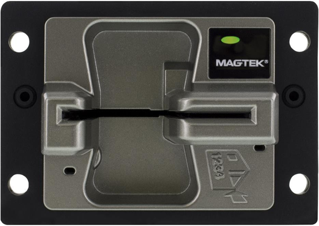
7811-3
Location of embossed characters
7811-4
Location of tracks 1 & 2
7811-5
Location of track 3
7811-6
Magnetic stripe - high coercivity
7813
Financial transaction cards
Measurement - 0.223"
Track
Recording Density (bits per inch)
Character Configuration (including parity bit)
Information Content (including control characters)
0.110"
1 IATA
210
7 bits per character
76 alphanumeric data characters between Format Code and Discretionary Data.
SS
FC
PAN
FS
Name
FS
Additional data
Discretionary Data
ES
SS: Start Sentinel - %
FC: Format Code - ^
PAN: Primary Account Number (19 digits max.)
FS: Field Separator
NAME: Name (26 alphanumeric characters max.)
ADDITIONAL DATA: Number of characters:
Expiration Date (YYMM) - 4
Service Code - 3
DISCRETIONARY DATA: Number of characters:
PVKI - PIN Verification Key Number
PVV or Offset - PIN Verification Value
ES: End Sentinel - ?
LRC: Logitudinal Redundancy Check character
37 data characters between PAN and Discretionary Data.
SS
PAN
FS
Additional data
Discretionary Data
ES
LRC
SS: Start Sentinel - Hex B - ;
PAN: Primary Account Number (19 digits max.)
FS: Field Separator - Hex D - =
ADDITIONAL DATA: Number of characters:
Expiration Date (YYMM) - 4
Service Code - 3
DISCRETIONARY DATA: Number of characters:
PVKI - PIN Verification Key Number
PVV or Offset - PIN Verification Value
ES: End Sentinel - Hex F - ?
LRC: Logitudinal Redundancy Check character
104 numeric data characters between Format Code and Additional Data.
SS
FC
PAN
FS
USE AND SECURITY DATA
Additional data
ES
LRC
SS: Start Sentinel - Hex B - ;
PAN: Primary Account Number (19 digits max.)
FS: Field Separator - Hex D - =
USE AND SECURITY DATA - Number of characters
Country Code (optional) - 3
Currency Code - 3
Currency Exponent - 1
Amount Authorized per Cycle - 4
ADDITIONAL DATA: Number of characters:
First subsidiary account number (optional)
Second subsidiary account number (optional)
ES: End Sentinel - Hex F - ?
LRC: Logitudinal Redundancy Check character
FC: Format Code - (2 digits) (in place of optional field)
7810
Physical characteristics of credit card size document
7811-1
Embossing
7811-2
Magnetic stripe - low coercivity
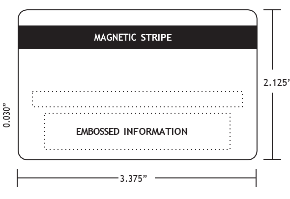
For copies of specifications contact: American National Standards Institute 11 W. 42nd Street, New York, NY 10036 212-642-4900
Some or all of the above Discretionary Data fields may be found with the discretionary data
A Field Separator (FS) must be used if an optional field is not used
The track formats used in this document are based on ISO Standards, however, other formats may be used. Contact your card issuer for your exact requirements
On the master workstation, navigate to the root of the SDK \Library\Java.
Open the \x86 subfolder and copy all the files to the target workstation’s C:\Windows\System32 folder for x86 systems, or to the target workstation’s C:\Windows\SysWOW64 folder for x64 systems.
Connect the device to the workstation using a USB cable. Windows will install the device drivers automatically. Wait for Windows to report the driver installation is complete.
Launch a Windows command prompt as an Administrator.
cd to the root of the folders where the SDK is installed.
Type runsample.bat and press Enter to launch the Java Demo software.
MagTek highly recommends using the 32-bit version of Java if you intend to use the Java applet, regardless of whether you are using a 32-bit or 64-bit version of Windows.
Uninstall any existing instances of the 32-bit Java Runtime Environment (JRE) or Java Development Kit (JDK). Leaving them installed can cause runtime failures, as the library may fail to load.
Download and install the latest version of the 64-bit Java Development Kit (JDK).
If you opted to manually copy the SDK dependencies from a master development workstation to the target workstation where it will be used, follow these steps:
On the master workstation, navigate to the root of the SDK \Library\Java
Open the x86 subfolder and copy all the files to the target workstation’s C:\Windows\System32 folder or to the target workstation’s C:\Windows\SysWOW64 folder for x64 systems.
Connect the device to the workstation using a USB cable. Windows will install the device drivers automatically. Wait for Windows to report the driver installation is complete.
Launch a Windows command prompt as an Administrator.
cd to the root of the folders where the SDK is installed.
Type runsample.bat and press Enter to launch the Java Demo software.
MagTek highly recommends using the 32-bit version of Java when using the Java applet, regardless of whether you are using a 32-bit or 64-bit version of Windows.
To set up the Java applet using the 32-bit version of Java on either a 32-bit or 64-bit version of Windows, follow these steps:
Follow the steps in section How to Set Up the Java Library With the 32-bit JRE/JVM. Having a working JVM, working Java library, working drivers, and working DLLs are prerequisites for using the applet.
Verify Java is installed and that the Internet Explorer Java plugin is working correctly by using Oracle’s Java applet test page, usually provided as a link or auto-launch at the end of installation.
On the Windows 7 workstation you will use for development, enable Internet Information Services 7 (IIS) as follows:
Log in to a Windows 7 workstation using an administrator account.
Launch the Windows Control Panel.
Select the Programs and Features item to open the Programs and Features page.
On the left side of the page, select the Turn Windows features on or off link to launch the Windows Features window.
Turn on the checkboxes for Internet Information Services and Internet Information Services Hostable Web Core.
Press the OK button to launch a progress window. Wait for Windows to install IIS.
Launch a web browser and navigate to //localhost . Verify the IIS default page appears as shown in Figure 2-1.
Figure 2-1 IIS Default Page
If it does not already exist, create a MTPPSCTA folder in C:\inetpub\wwwroot\ . If it does exist, delete its contents.
On the workstation where the SDK is installed, navigate to the folder where it is installed.
Open the Sample Code\Java Applet\Object\Signed subfolder.
Copy the contents of the subfolder to C:\inetpub\wwwroot\MTCMS .
Open the Sample Code\Java Applet\Object\x85 subfolder.
Copy the contents of the subfolder to C:\inetpub\wwwroot\MTCMS.
Figure 2-2 - inetpub Structure
Connect the device to the workstation using a USB cable. Windows will install the device drivers automatically. Wait for Windows to report the driver installation is complete.
Open Internet Explorer as an administrator.
If you are using a 64-bit version of Windows with IE11, make sure to launch directly in 32-bit mode using the iexplore.exe found in C:\Program Files (x86). Verify you are running in 32-bit mode using the Help>About menu.
If you are running a 64-bit version of Windows with IE10 or higher, choose the Internet options that enable 32-bit mode / disable Protected Mode for the zone you are accessing. Also turn OFF the checkbox for Enhanced Protected Mode in the Internet Options > Advanced tab.
If you changed the value of the Enable Enhanced Protected Mode checkbox, restart Windows.
Open Windows Task Manager (Ctrl-Alt-Del > Start Task Manager).
Open the Processes tab and sort by Image Name.
Note the number and location of all iexplore.exe *32 processes.
In Internet Explorer, navigate to
In the Windows Task Manager Processes tab, find the new process for the Internet Explorer tab you just opened and make sure it is running in 32-bit mode ( iexplore.exe *32 instead of iexplore.exe.
Close the Windows Task Manager window.
Internet Explorer will display a welcome page and will pop up a Do you want to run this application? window. Press the Run button and the Allow button to run the Java applet.
On the welcome page, press the Connect button.
Press the Get Info button. The large text box in the browser will display device information.
Use the buttons and fields on the welcome page to test the connection to the device.
After installation on the workstation is complete, future browser sessions do not require the user to launch Internet Explorer as an administrator to use the applet.
The Caller-Allowable-Codebase attribute is used to identify the domains from which JavaScript code can make calls to your RIA without security prompts. Set this attribute to the domain that hosts the JavaScript code. If a call is made from JavaScript code that is not located in a domain specified by the Caller-Allowable-Codebaser attribute, the call is blocked. To specify more than one domain, separate the domains by a space, for example:
The Application-Library-Allowable-Codebase attribute identifies the locations where your signed RIA is expected to be found. This attribute is used to determine what is listed in the Location field for the security prompt that is shown to users when the JAR file for your RIA is in a different location than the JNLP file or HTML page that starts your RIA. If the files are not in the locations identified, the RIA is blocked. Set this attribute to the domains where the JAR file, JNLP file, and HTML page are located. To specify more than one domain, separate the domains by a space, for example:
For more information regarding the JAR File Manifest Attributes for Security, please visit this website http://docs.oracle.com/javase/7/docs/technotes/guides/jweb/security/manifest.html
In order to modify the Manifest file, please follow these steps. You need to do this for: magtek-mtcms-lib.jar.
Find installation folder by default, the installation folder is: \Sample Code\Java Applet\Object\Unsigned.
Launch the command prompt and extract the META-INF/MANIFEST.MF from the jar file.
Open MANIFEST.MF and look for the Caller-Allowable-Codebase and Application-Library-Allowable-Codebase and add your website URL to the list like the example above.
Update the manifest to the jar file.
These instructions provide an overview of obtaining and using Sun Java signing and a digital certificate. Please follow this instruction to sign and verify both MTCMSJavaSample.jar magtek-mtmcms-lib.jar.
Make sure your machine has the latest Java JDK installed.
Generate a public/private key pair by entering the following command, specifying an alias for your keystore:
Generate a certificate signing request (CSR) by entering the following command:
After prompting you to enter the password for your keystore, keytool will generate a CSR.
Save the certificate received from the Certificate provider as Certname.p7b.
Import your Digital Certificate by entering the following command:
In this string, keytool is requested to import the Digital ID “Certname.cer” into the keystore MyCert.
Bundle your applet into a Java Application Resource (JAR) file by entering the following command:
Sign the files by using jarsigner to sign the JAR file, using the private key you saved in your keystore:
Verify the output of your signed JAR file by entering the following command:
Please visit this website https://docs.oracle.com/javase/tutorial/deployment/jar/signing.html for more information regarding signing JAR files.
Caller-Allowable-Codebase: *.yahoo.com *.google.com *.magtek.com *Application-Library-Allowable-Codebase: *.yahoo.com *.google.com *.magtek.com *jar xf magtek-mtcms-lib.jar META-INF/MANIFEST.MFjar umf META-INF/MANIFEST.MF magtek-mtcms-lib.jarkeytool -genkey -keyalg rsa -alias MyCertkeytool -certreq -alias MyCertkeytool -import -alias MyCert -file Certname.p7bjar cvf C:\MTCMSJavaSample.jarjarsigner C:\Magtek-ppscra-applet.jar MyCert
jarsigner C:\magtek-mtcms-lib.jar MyCertjarsigner -verify -verbose -certs C:\Magtek-ppscra-applet.jar
jarsigner -verify -verbose -certs C:\magtek-mtcms-lib.jarTechnical references for developers including the Commands Programmer's Manual, the Microsoft .NET/Java/Applet Programmer's Manual, the MTCMS Demo guide, and the SCRA EMV Flowchart
Supporting resources such as the EMV Configuration Software Instructions for verifying EMV configuration via USB, the debris clearing tool manual , the device inspection manual for tamper detection and PCI PTS compliance, and marketing brochures including the oDynamo Hybrid Card Reader Brochure.
This page provides the compliance documentation required to maintain PCI PTS approval for the oDynamo hybrid insertion secure card reader authenticator (SCRA), including the device and package inspection guides for tamper detection and physical security verification.
Reference Section
Information Available
essential software resources for developing with and managing the oDynamo secure card reader, including platform-specific SDKs for integration across Linux, Windows, .NET, and Java, as well as utility programs for device demonstration, remote configuration, and enterprise‑scale firmware and setting updates.
Reference Section
Information Available
End‑user and integrator documentation including the Installation and Operation Manual for design guidelines, mounting instructions, and host connectivity, along with the MagTek Reader Management System guide for firmware and CAPK updates.
Need Help?
For additional support, please contact MagTek Support:
Technical Support:
📧 Email:
High-performance, low-cost three-channel magnetic stripe decoder chips that significantly simplify the card-reader-to-micro-controller interface, including the Delta ASIC (proven for three-track reading) and the next-generation Qwantum ASIC with integrated encryption, SPI support, and ultra-low power modes.
An EMV contact chip card reader module that connects via USB, features two optional auxiliary ports (SPI and UART) to easily add magnetic stripe or contactless/NFC reading, and is built on the MagneSafe Security Architecture for secure chip card transactions.
A compact bidirectional magnetic stripe swipe reader available in USB keyboard emulation or HID format, designed for low‑cost, high‑reliability card reading in payment, membership, loyalty, and identification applications.
Highly efficient three-channel fully integrated magnetic stripe decoder chips (including the Delta and Qwantum families) that simplify the card-reader-to-micro-controller interface via MagTek's "Shift-Out" protocol while supporting advanced features like integrated encryption, SPI, and USB-C connectivity.
Modular card guide rails that work with MagTek’s IntelliHead product line (including the encrypted MagneSafe™ IntelliHead) to provide a complete card swipe assembly in lengths such as 43mm, 60mm, 70mm, and 90mm for various OEM integration needs.
A low-profile magnetic read head with an embedded high-performance multi-channel decoder chip that outputs raw track data using the simple "Shift-Out" protocol (data/strobe), making it ideal for battery-powered or microcontrollers where minimal power consumption is critical.
Need Help?
For additional support, please contact MagTek Support:
Technical Support:
📧 Email: support@magtek.com
📞 Phone: 1-562-546-6800 (US)
🕐 Hours: Monday-Friday, 5:30 AM - 5:00 PM PST
Online Resources:
🌐 Support Portal: developer.magtek.com
Documentation Feedback:
Help us improve this documentation!
Command 0x04::0x09 - Read MSR Data
The host uses this command to arm the device’s MSR to read magnetic stripe data after the device reports an EMV transaction using a chip card has failed. The command is intended to be used to implement fallback when Command 0x07::0x80 - EMV L2 Transaction Status or Notification 0x07::0x8A - EMV L2 Transaction Status report statuses EMV Error - Card Blocked or Empty Candidate List. If the host wishes to fall back to reading MSR data upon receiving those status reports, it must invoke this command while the card is still inserted, and the device will read the magnetic stripe when the cardholder removes the card from the slot, then send its response to the host to return the requested data.
Although this command is intended to be used after EMV transaction failure, if the host calls it outside the context of an EMV transaction, the command will function the same: The MSR reader will continue to be armed, and the device will return MSR card data in the response upon card removal.
Notification 0x04::0x11 - MSR Card Data Available
When a cardholder swipes a magnetic stripe card, the device sends this notification to inform the host that card data is available. After receiving this notification, the host should call Command 0x04::0x12 - Request MSR Card Data to get the data.
Command 0x04::0x12 - Request MSR Card Data
The host uses this command to request MSR data after receiving Notification 0x04::0x11 - MSR Card Data Available.
Thank you for purchasing oDynamo Development Kit 21060861. MagTek has designed this kit to help you quickly connect oDynamo to a host and activate it so you can begin testing and development.
To set up oDynamo with your test host using the contents of the kit, follow these steps:
From the Manuals tab of the oDynamo Support page on www.magtek.com, download the latest product documentation. This includes:
oDynamo Installation and Operation Manual, which provides an overview of the product and deep detail about integrating it into a solution design.
oDynamo Programmer’s Manual (COMMANDS), which provides details about the internal logical workings of the device and about communicating directly (without an SDK) using operating system native communication libraries and the device’s native commands.
From the Software tab of the oDynamo Support page, download the latest SDKs that pertain to your chosen development framework, which may include:
oDynamo MTCMS .NET SDK for Windows
oDynamo MTCMS C++ / Java SDK for Windows
In the oDynamo Installation and Operation Manual, become familiar with the device’s major components, shown in the section About oDynamo Components . The device’s four connectors and the General Status LED are of particular importance in setting up the development kit.
In the oDynamo Installation and Operation Manual, become familiar with the device’s mount and dismount behaviors, documented in the section About Pre-Activision, Activation, and Re-Activation . After installing the clip-on dismount switch lock included in this kit, it is important to not remove it without already knowing how to re-activate the device.
Unpack oDynamo, which is sold separately from the kit.
Select the oDynamo connector you will use to communicate with the host (USB, Ethernet, or RS-232), and connect the appropriate cable(s) as follows, depending on connection type:
To use the RS-232 and Power Port [J1] to communicate with the host using RS-232:
Connect the 9-pin DIN serial data leg of the RS-232 / power cable (1000004111) to the host.
Connect the other signal leg of the cable to the device’s RS-232 and Power Port [J1].
To use the USB Device Port [J3] to communicate with the host using USB:
Connect the USB cable (22350300) to the device’s USB Device Port [J3].
Connect the other end of the cable to the host’s USB port.
To use the Ethernet Port [J4] to communicate with the host using TCP/IP:
Connect the Ethernet cable (71900032) to the device’s Ethernet Port [J4].
Connect the other end of the Ethernet cable to a network switch on the same network segment as the host, or appropriate network drop on the LAN.
Engage the device’s dismount switches by connecting the clip-on dismount switch lock 1000005104:
Connect the power supply (1000004941) to a properly grounded AC socket-outlet.
Make sure the power supply LED turns on and that the device’s General Status LED is blinking yellow to show the device is in the Pre-Activated state.
oDynamo is now ready for testing and development. See the product documentation and the sample code / demonstrations / documentation in the SDKs to do the following:
Amount Remaining this Cycle - 4
Cycle Begin (Validity Date) - 4
Cycle Length - 2
Retry Count - 1
PIN Control Parameters (optional) - 6
Interchange Controls - 1
PAN Service Restriction - 2
SAN-1 Service Restriction - 2
SAN-2 Service Restriction - 2
Expiration Date (optional) - 4
Card Sequence Number - 1
Card Security Number (optional) - 9
Cryptographic check digits (optional) - 6
Discretionary Data
79 alphanumeric characters
0.110"
ABA
75
5 bits per character
40 numeric characters
0.110"
THRIFT
210
5 bits per character
107 numeric characters
LRC
📞 Phone: 1-562-546-6800 (US)
🕐 Hours: Monday-Friday, 5:30 AM - 5:00 PM PST
Online Resources:
🌐 Support Portal: developer.magtek.com
Documentation Feedback:
Help us improve this documentation! feedback@magtek.com
Connect the other end of the power-only cable to the power supply (1000004941).
Connect the other end of the power-only cable to the power supply (1000004941).
Test the connection between the device and the host.
Send an Activate Device from command and make sure the device’s General Status LED transitions from Pre-Activated to Ready.
Test the device’s card reading capabilities.
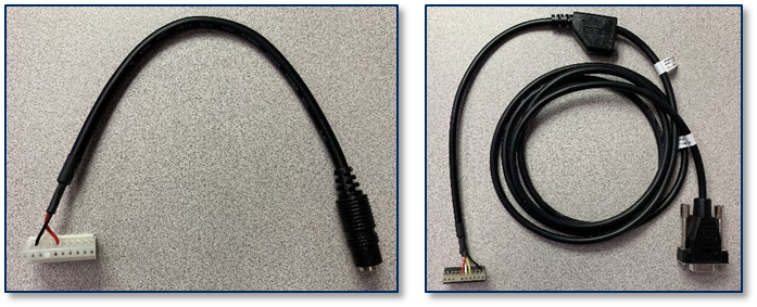
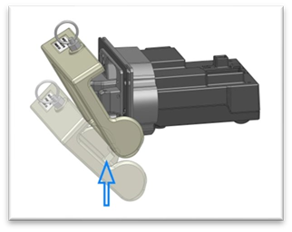
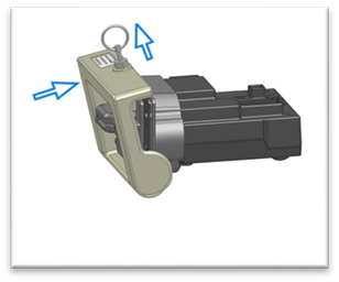
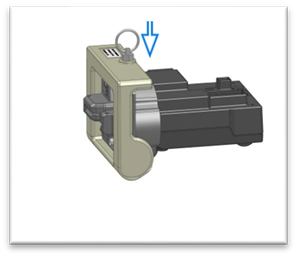


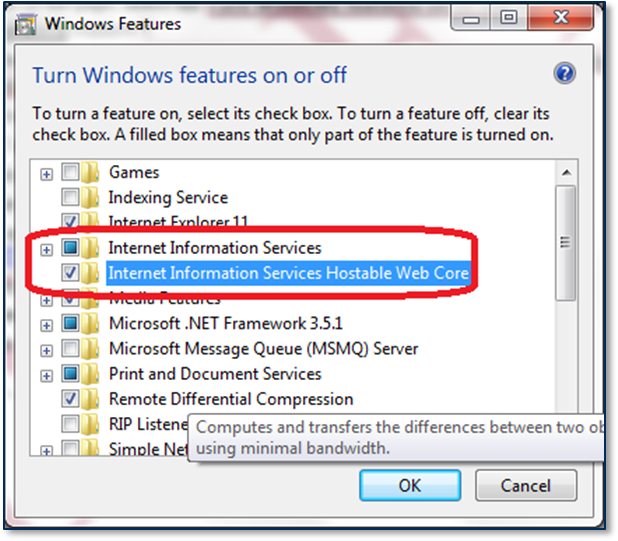
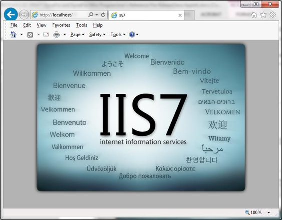
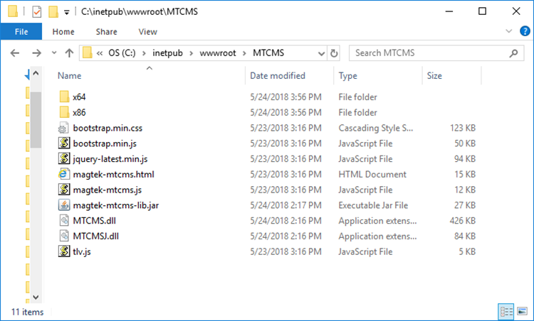
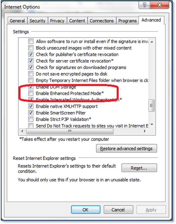
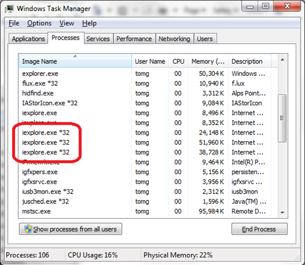
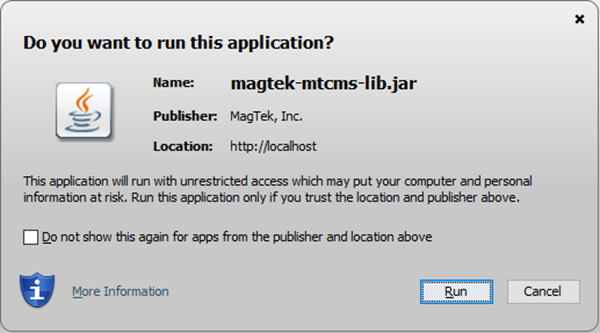
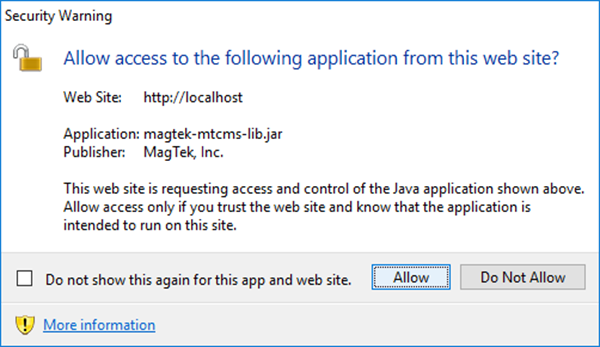
Add LED detail to section 5.2; Add section 1.9 and section 7; Completely rewrite section 3; Remove USB Host Port [J2]; Misc. clarifications, corrections, quality improvements.
21
May 22, 2018
Add clarifying details about grounding in section 2.2; Provide detailed current requirement calculations in section 2.5, Misc. clarifications and corrections.
22
May 23, 2019
Table 5-1 clarify dismount and re-mount requires re-activation using a signed command; Add an introduction to section 4 Installation and new subsection about activation to clarify solution design requirements for install / uninstall security features; Misc. clarifications and corrections.
23
Mar 23, 2021
6.1 add information about debris clearing maintenance, reorder maintenance advice in order of importance.
30
Aug 26, 2021
1.8, 3.4, 3.5, 4, 4.1, 5.2, and whole section “About Pre-Activation, Activation, and Re-Activation” remove mention of dismount switches as a security function; 1.2, 3.1, 3.3, Appendix A remove mention of vertical mounting as a supported orientation; Misc. clarifications and corrections.
31
Sep 22, 2021
3.3 clarify horizontal orientation for optimum results; Misc. clarifications and corrections.
32
Oct 20, 2021
Update Software License Agreement, RoHS Statement.
33
June 6, 2022
Change EMV Contact chip insertions to 500K from 200K.

01
04
Application ID Data Object (Tag C1) = 0x04 MSR Messages
C2
01
09
Command ID Data Object (Tag C2) = 0x09 Read MSR Data
C3
01
00
Result Code Data Object (Tag C3) = 0x00 OK / Done
C4
Calculated
Data Field Data Object (Tag C4 or E0) =
If Result Code is OK / Done, this contains magnetic stripe data as documented in Data Object F4 - Magnetic Stripe Reader Card Data, otherwise the response will not include data object C4.
01
04
Application ID Data Object (Tag C1) = 0x04 MSR Messages
C2
01
11
Command ID Data Object (Tag C2) = 0x11 MSR Card Data Available
Data Field Data Object (Tag C4 or E0) = Byte 0 Card type
0x00 = Other 0x01 = ISO
0x02 = AAMVA
0x99 = MSR_OPERATION_ERROR
Byte 1 Account Data whitelist comparison result (see Command 0x03::0x80 - Read PAN Whitelist / Account Data Whitelist)
0x00 = The card does not match any rule in the Account Data whitelist, device will send data encrypted.
0x01 = The card matches one or more rules in the Account Data whitelist, device will send data unencrypted.
01
04
Application ID Data Object (Tag C1) = 0x04 MSR Messages
C2
01
12
Command ID Data Object (Tag C2) = 0x12 Request MSR Card Data
01
04
Application ID Data Object (Tag C1) = 0x04 MSR Messages
C2
01
12
Command ID Data Object (Tag C2) = 0x12 Request MSR Card Data
C3
01
00
Result Code Data Object (Tag C3) = 0x00 OK / Done
C4
Calculated
Data Field Data Object (Tag C4 or E0) =
If Result Code is OK / Done (0x00), this contains magnetic stripe data as documented in Data Object F4 - Magnetic Stripe Reader Card Data, otherwise the response includes a 1-byte error code.
Tag
Len
Value(s) / Description
C0
01
01
Message Type Data Object (Tag C0) = 0x01 Command
C1
01
04
Application ID Data Object (Tag C1) = 0x04 MSR Messages
C2
01
09
Command ID Data Object (Tag C2) = 0x09 Read MSR Data
Tag
Len
Value(s) / Description
C0
01
02
Message Type Data Object (Tag C0) = 0x02 Response
Tag
Len
Value(s) / Description
C0
01
03
Message Type Data Object (Tag C0) = 0x03 Notification
Tag
Len
Value(s) / Description
C0
01
01
Message Type Data Object (Tag C0) = 0x01 Command
Tag
Len
Value(s) / Description
C0
01
02
Message Type Data Object (Tag C0) = 0x02 Response
C1
C1
C1
C1
After creating an instance of the MTDevice class in your software project, use the methods described in this section to communicate with MagTek CMS device.
This method initiates request to discover devices that are visible to the host using the specified connection interface. The OnDeviceList event will provide information regarding the available devices once the discovery process is completed.
public void requestDeviceList(MTConnectionType connectionType)Parameters:
Parameter
Description
Return Value: None
This method sets the connection type of the device..
Parameters:
Return Value: None
This method sets the address of the device.
Parameters:
The following table shows the address formats supported by the different connection types:
Return Value: None
This method sets the device ID.
Parameters:
Return Value: None
This method opens the connection to the device.
Parameters: None
Return Value: None
This method closes the connection to the device.
Parameters: None
Return Value: None
This method returns whether the device is connected or not.
Parameters: None
Return Value:
Return true if the device is connected. Otherwise, return false.
This method sends a data string to the device.
Parameters:
Return Value:
0 = Success (MTDevice.SEND_SUCCESS)
9 = Error (MTDevice.SEND_ERROR)
15 = Busy (MTDevice.SEND_BUSY)
This method sends data bytes to the device.
Parameters:
Return Value:
0 = Success (MTDevice.SEND_SUCCESS)
9 = Error (MTDevice.SEND_ERROR)
15 = Busy (MTDevice.SEND_BUSY)
This method sends a MagTek CMS message to the device.
Parameters:
Return Value:
0 = Success (MTDevice.SEND_SUCCESS)
9 = Error (MTDevice.SEND_ERROR)
15 = Busy (MTDevice.SEND_BUSY)
C4
03
Byte 2 PAN status (see Command 0x03::0x80 - Read PAN Whitelist / Account Data Whitelist)
0x00 = The card does not match any rule in the PAN whitelist. No PAN is available.
0x01 = The card matches one or more rules in the PAN whitelist. Full cleartext PAN for PIN block construction is available.
0x02 = The card matches one or more rules in the PAN whitelist. Partial cleartext PAN for PIN block construction is available.
0x03 = The card does not match any rule in the PAN whitelist, but an encrypted PAN is available for use with a paired Cryptera EPP.
0x99 = MSR_OPERATION_ERROR
IP
[PORT]
The TCP port of the device. (Default: 5000)
[PARITY]
The parity checking protocol. (Default: NONE).
Supported Values: NONE,EVEN,ODD,SPACE,MARK
[STOPBITS]
The number of stop bits per byte. (Default: 1)
Supported Values: 1,1.5,2
[HANDSHAKE]
The handshaking protocol for serial port transmission of data.
(Default: NONE)
Supported Values: NONE,RTS,XONXOFF,RTSXONSOFF
[STARTINGBYTE]
The special character used as the starting byte for each message.
(Default is empty string)
An empty string indicates no special character is used as the starting byte for each message.
[ENDINGBYTE]
The special character used as the ending byte for each message.
(Default is 0x0A)
connectionType
MTConnectionType value: MTConnectionType.USB, MTConnectionType.IP, MTConnectionType.Serial
Parameter
Description
connectionType
MTConnectionType value: MTConnectionType.USB, MTConnectionType.IP, MTConnectionType.Serial
Parameter
Description
deviceAddress
String value of the address.
Connection Type
Address Format Parameter
Address Format Descroption
USB
[PATH]
The OS specific device path to the USB device. The path is normally retrieved from the Address property of MTDeviceInformation.
IP
[IPA]
Parameter
Description
Serial
PORT=[PORT],
BAUDRATE=[BAUDRATE],
DATABITS=[DATABITS],
PARITY=[PARITY],
STOPBITS=[STOPBITS],
HANDSHAKE=[HANDSHAKE],
STARTINGBYTE=[STARTINGBYTE],
ENDINGBYTE=[ENDINGBYTE],
CRCMODE=[CRCMODE]
Parameter
Description
[PORT]
The OS specific device path to the serial port (i.e. COM4).
[BAUDRATE]
The data baud rate . (Default: 9600)
[DATABITS]
The data bits per byte. (Default: 8)
Connection Type
Address Format
An empty string indicates no special character is used as the ending byte for each message
[CRCMODE]
A value of 0 indicates CRC is disabled, otherwise CRC is enabled.
(Default: 0)
Parameter
Description
deviceID
String value of the device ID.
Parameter
Description
dataString
Data to be sent in hexadecimal string format.
Parameter
Description
dataBytes
Data to be sent in byte array format.
Parameter
Description
message
MTCMSMessage to be sent to the device.
The IP address of the device in dotted-quad notation (i.e. 192.178.1.123).
public void setConnectionType(MTConnectionType connectionType)public void setAddress(string deviceAddress)public void setDeviceID(string deviceID)public void openDevice()public void closeDevice()public bool isDeviceConnected()public int sendDataString(string dataString)public int sendDataBytes(byte[] dataBytes)public int sendMTCMSMessage(MTCMSMessage message)// #1
MTSCRA m_SCRA = new MTSCRA();
// Delegate the MTSCRA Events. m_SCRA.OnDisplayMessageRequest += OnDisplayMessageRequest;
.
// Assign parameters.
byte timeLimit = 0x3C;
byte cardType = 0x07;
byte option = 0x00;
byte[] amount = new
byte[] { 0x00, 0x00, 0x00, 0x00, 0x15, 0x00 };
byte transactionType = 0x00; // Purchase
byte[] cashBack = new byte[] { 0x00, 0x00, 0x00, 0x00, 0x00, 0x00 };
byte[] currencyCode = new byte[] { 0x08, 0x40 };
byte reportingOption = 0x02; // All Status Changes
// Start transaction.
long result = m_SCRA.startTransaction(
timeLimit,
cardType,
option,
amount,
transactionType,
cashBack,
currentCode,
reportingOption);// #2
protected void OnDisplayMessageRequest(obj sender, byte[] data)
{
String message;
// Get the message.
if (data != NULL)
{
message = System.Text.Encoding.UTF8.GetString(data);
}
// A data size of 0 is an instruction to clear the display.
if (data.Length == 0)
{
// Clear the display.
}
}// #3
protected void OnUserSelectionRequest(object sender, byte[] data)
{
/* data[0] – selection type
data[1] – timeout
data[2..n] – remainder contains zero-terminated string items */
// display/retrieve user selection.
.
// set status and selection result.
m_SCRA.setUserSelectionResult(status, selection);
}// #4
protected void OnARQCReceived(object sender, byte[] data)
{
/* data[0..1] – ARQC length
data[2..n] – remainder contains the ARQC TLV object */
// #4a Forward ARQC to Processor.
/* An application function to forward the ARQC
to a Processor for approval. */
proccesorResponse = sendARQCToProcesor(data);
/* No need to send ARQC Response if transaction option
had enabled Quick Chip mode. */
if (isQuickChipEnabled())
{
return;
}
// #4b Set Acquirer Response.
// An application function to build Acquirer Response.
byte[] response = buildAcquirerResponse(processorResponse);
// Set Acquirer Response.
m_SCRA.setAcquirerResponse(response);
}// #5
protected void OnDisplayMessageRequest(obj sender, byte[] data)
{
String message;
// Get the message.
if (data != NULL)
{
message = System.Text.Encoding.UTF8.GetString(data);
}
// A data size of 0 is an instruction to clear the display.
if (data.Length == 0)
{
// Clear the display.
}
}REGISTERED TO ISO 9001:2015
Copyright © 2006 - 2025 MagTek, Inc. Printed in the United States of America
INFORMATION IN THIS PUBLICATION IS SUBJECT TO CHANGE WITHOUT NOTICE. MAGTEK CANNOT BE HELD LIABLE FOR ANY USE OF THE CONTENTS OF THIS DOCUMENT. ANY CHANGES OR IMPROVEMENTS MADE TO THIS PRODUCT WILL BE INCLUDED IN THE NEXT PUBLICATION RELEASE. IF YOU HAVE QUESTIONS ABOUT SPECIFIC FEATURES AND FUNCTIONS OR WHEN THEY WILL BECOME AVAILABLE, PLEASE CONTACT YOUR MAGTEK REPRESENTATIVE.
MagTek®, MagnePrint®, and MagneSafe® are registered trademarks of MagTek, Inc. Magensa™ is a trademark of MagTek, Inc.
DynaPro™ and DynaPro Mini™, are trademarks of MagTek, Inc.
AAMVA™ is a trademark of AAMVA.
American Express® and EXPRESSPAY FROM AMERICAN EXPRESS® are registered trademarks of American Express Marketing & Development Corp.
D-PAYMENT APPLICATION SPECIFICATION® is a registered trademark to Discover Financial Services CORPORATION MasterCard® is a registered trademark and PayPass™ and Tap & Go™ are trademarks of MasterCard International Incorporated. Visa® and Visa payWave® are registered trademarks of Visa International Service Association.
ANSI®, the ANSI logo, and numerous other identifiers containing "ANSI" are registered trademarks, service marks, and accreditation marks of the American National Standards Institute (ANSI).
ISO® is a registered trademark of the International Organization for Standardization. UL™ and the UL logo are trademarks of UL LLC.
PCI Security Standards Council® is a registered trademark of the PCI Security Standards Council, LLC.
EMV® is a registered trademark in the U.S. and other countries and an unregistered trademark elsewhere. The EMV trademark is owned by EMVCo, LLC. The Contactless Indicator mark, consisting of four graduating arcs, is a trademark owned by and used with permission of EMVCo, LLC.
The Bluetooth® word mark and logos are registered trademarks owned by Bluetooth SIG, Inc. and any use of such marks by MagTek is under license.
Google Play™ store, Google Wallet™ payment service, and Android™ platform are trademarks of Google Inc.
Apple Pay®, iPhone®, iPod®, Mac®, and OS X® are registered trademarks of Apple Inc., registered in the U.S. and other countries. iPad™ is a trademark of Apple. Inc. App StoreSM is a service mark of Apple Inc., registered in the U.S. and other countries. IOS is a trademark or registered trademark of Cisco in the U.S. and other countries and is used by Apple Inc. under license.
Microsoft®, Windows®, and .NET® are registered trademarks of Microsoft Corporation. All other system names and product names are the property of their respective owners.
Table 0-1 - Revisions
Rev Number
Date
Notes
100
January 30, 2025
Initial Release

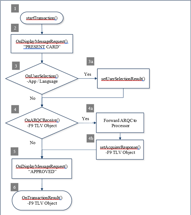
// #6
protected void OnTransactionResult(obj sender, byte[] data)
{
/* data[0] – Signature Required
data[1..2] – Batch Data length
data[3..n] – remainder contains the Batch Data TLV object */
// Parse the TLV from data[].
.
// Abstract Approval status from TLV tag “DFDF1A”.
.
// Abstract Signature Required status from TLV tag data[0].
.
}
// #1
m_MTSCRA = new MTSCRA(this, m_scraHandler);
// Assign parameters.
byte timeLimit = 0x3C;
byte cardType = 0x07;
byte option = 0x00;
byte[] amount = new byte[] { 0x00, 0x00, 0x00, 0x00, 0x15, 0x00 };
byte transactionType = 0x00; // Purchase
byte[] cashBack = new byte[] { 0x00, 0x00, 0x00, 0x00, 0x00, 0x00 };
byte[] currencyCode = new byte[] { 0x08, 0x40 };
byte reportingOption = 0x02; // All Status Changes
// Start transaction.
m_MTSCRA.startTransaction(
timeLimit,
cardType,
option,
amount,
transactionType,
cashBack,
currencyCode,
reportingOption);
int result = m_MTSCRA.getResultCode();// #2
protected void onDisplayMessageRequest(byte[] data)
{
String message;
// Get the message.
if (data != NULL)
{
message = TLVParser.getTextString(data, 0);
}
// A data size of 0 is an instruction to clear the UI display.
if (data.Length == 0)
{
// Clear the display.
}
}// #3
protected void onUserSelectionRequest(byte[] data)
{
/* data[0] – selection type
data[1] – timeout
data[2..n] – remainder contains user selection strings delimited by “\0”.
*/
// display/retrieve status and user selection.
byte status;
byte selection;
.
.
// set status and selection result.
m_MTSCRA.setUserSelectionResult(status, selection);
}// #4
protected void onARQCReceived(byte[] data)
{
/* data[0..1] – ARQC length
data[2..n] – remainder contains the ARQC TLV object */
// #4a Forward ARQC to Processor.
/* An application function to forward the ARQC
to a Processor for approval. */
proccesorResponse = sendARQCToProcesor(data);
/* No need to send ARQC Response if transaction option had enabled Quick Chip mode. */
if (isQuickChipEnabled())
{
return;
}
// #4b Set Acquirer Response.
// An application function to build Acquirer Response.
byte[] response = buildAcquirerResponse(processorResponse);
// Set Acquirer Response.
m_MTSCRA.setAcquirerResponse(response);
}// #5
protected void onDisplayMessageRequest(byte[] data)
{
String message;
// Get the message.
if (data != NULL)
{
message = TLVParser.getTextString(data, 0);
}
// A data size of 0 is an instruction to clear the UI display.
if (data.Length == 0)
{
// Clear the display.
}
}// #6
protected void onTransactionResult(byte[] data)
{
/* data[0] – Signature Required
data[1..2] – Batch Data length
data[3..n] – remainder contains the Batch Data TLV object */
// Parse the TLV from data.
.
// Abstract Approval status from TLV tag “DFDF1A”.
.
// Abstract Signature Required status from TLV tag data[0].
.
}// #1
self.mtSCRALib = [[MTSCRA new];
// Delegate the MTSCRA Events.
[[NSNotificationCenter defaultCenter] addObserver:self selector:@selector(onDisplayMessageRequest:) name:@" onDisplayMessageRequest" withObject:obj];
.
.
// Assign parameters.
Byte timeLimit = 0x3C;
Byte cardType = 0x07;
Byte option = 0x00;
Byte amount[6] = { 0x00, 0x00, 0x00, 0x00, 0x15, 0x00 };
Byte transactionType = 0x00; // Purchase
Byte cashBack[6] = { 0x00, 0x00, 0x00, 0x00, 0x00, 0x00 };
Byte currencyCode[2] = { 0x08, 0x40 };
Byte reportingOption = 0x02; // All Status Changes
// Start transaction.
[self.mtSCRALib startTransaction:timeLimit cardType:cardType
option:option amount:amount transactionType:transactionType
cashBack:cashBack currencyCode:currencyCode
reportingOption:reportingOption];// #2
-(void)OnDisplayMessageRequest:(NSData *)data
{
// Get the message.
NSString* message = [HexUtil stringFromHexString:[self
getHexString:data]];
// A data size of 0 is an instruction to clear the display.
if (message.Length == 0)
{
// Clear the display.
}
}// #3
-(void)OnUserSelectionRequest:(NSData *)data
{
/* data[0] – selection type
data[1] – timeout
data[2..n] – remainder contains zero-terminated string items */
// display/retrieve user selection.
.
// set status and selection result.
[self.mtSCRALib.setUserSelectionResult:(Byte)status
selection(Byte)userSelection];
}// #4
-(void)OnARQCReceived:(NSData *)data
{
/* data[0..1] – ARQC length
data[2..n] – remainder contains the ARQC TLV object */
// #4a Forward ARQC to Processor.
/* An application function to forward the ARQC
to a Processor for approval. */
proccesorResponse = sendARQCToProcesor(data);
/* No need to send ARQC Response if transaction option
had enabled Quick Chip mode. */
if (isQuickChipEnabled())
{
return;
}
// #4b Set Acquirer Response.
// An application function to build Acquirer Response.
NSData* response = buildAcquirerResponse(processorResponse);
// Set Acquirer Response.
[self.mtSCRALib.setAcquirerResponse:(unsigned char *)response
length:(int)response.length];
}// #5
-(void)OnDisplayMessageRequest:(NSData *)data
{
// Get the message.
NSString* message = [HexUtil stringFromHexString:[self
getHexString:data]];
// A data size of 0 is an instruction to clear the display.
if (message.Length == 0)
{
// Clear the display.
}
}// #6
-(void)OnTransactionResult:(NSData *)data
{
/* data[0] – Signature Required
data[1..2] – Batch Data length
data[3..n] – remainder contains the Batch Data TLV object */
// Parse the TLV from data[].
.
// Abstract Approval status from TLV tag “DFDF1A”.
.
// Abstract Signature Required status from TLV tag data[0].
.
}
This document describes how to use oDynamo safely and securely. Using the device in any way other than the approved methods described in this document invalidates the PCI PTS approval of the device.
Not following the guidelines in this section could damage the device, render it inoperable, and/or violate the conditions of the warranty.
This section provides information and guidelines for designing the electrical aspects of a solution that incorporates oDynamo. MagTek strongly recommends vetting and testing solution designs before finalizing and deploying them, to make sure the design meets all requirements (e.g., functional, legal, security, certification, safety, and so on).
When designing the electrical portions of a solution that incorporates oDynamo, consider the following:
Review section 1.6 About oDynamo Components for an overall introduction to the device’s physical features and what they are called.
Review Appendix A Technical Specifications.
See all the subsections below for options and constraints involving cable design, signals, power, and other aspects of electrical integration. To coordinate with the solution’s mechanical design team about cables, see section 3.6 Cabling.
Consider additional factors that may affect the electrical aspects of the solution design. See section
Review safe handling practices in section 1.9 Handling to make sure the logistical aspects of the solution design meet the device’s handling requirements.
Review recommended installation practices in section 4 Installation. The steps provided in that section depend on the solution design team to customize the steps or fill in solution-specific details before distribution to installation technicians.
Review section 6 Maintenance. When installed in the solution-specific enclosure, the maintenance procedures may require modifications, or the solution may require additional maintenance not covered in the general guidelines provided here.
To guard against ground loops and to protect the device against electrostatic discharge (ESD), it is important that solution designs ground the device correctly. MagTek strongly recommends checking whether the host’s communication ports provide earth ground, and whether the cables carry that ground all the way to the corresponding ports on the device’s board. This will help make an informed decision about proper grounding. There are three paths to provide earth ground to the device; MagTek recommends all solution designs bring in earth ground to the device using one and only one of the possible paths:
Bring in earth ground through pin 10 of the RS-232 and Power Port [J1]
Bring in earth ground through pin 1 and pin 2 of the Alternative Earth Grounding Port [J9]
Bring in earth ground from the host through the USB cable’s metal connector shell to the USB Device Port [J3]
If it is not practical to connect earth ground using only one of the available paths (for example, if the solution uses multiple shielded cables that provide earth ground from the host), then the solution design must ensure that every source of external earth ground is at the same electrical potential, to prevent damaging ground loop currents from occurring. MagTek also recommends using an earth ground isolated power supply (i.e., with the power supply’s negative output not connected to earth ground) like the one shown in Figure 2-1, because a non-isolated supply would connect digital ground to earth ground, defeating the separation of digital ground from earth ground on the device’s PCBs.
Figure 2-1 - Example Earth Ground Isolated 24V Regulated Power Supply
In addition, solutions that incorporate devices with a metal bezel must ground the bezel to the same earth ground potential as the point chosen above. This provides an additional path to protect the device from electrostatic discharge during card insertion and provides additional protection for the device’s electronics. MagTek recommends this earth grounding cable comprise two 18AWG stranded wires twisted together to form a Y cable. Figure 2-2 shows a prototype example of a Y cable that could be included in a standard installation kit.
MagTek recommends using shielded cables to provide noise immunity and to prevent radiated emissions. The device itself has been tested by an FCC lab for Class B radiated susceptibility and has no special shielding requirements. For details, see the FCC information provided at the beginning of this document.
MagTek also recommends that all communication cabling (i.e., USB, Ethernet, RS-232) should be draped together where possible, and isolated from the earth grounding cable to oDynamo and any other unrelated wiring at the installation site that could potentially couple noise into the device and degrade the low-level MagnePrint head signals.
The device has no special requirements for power conditioning or signal conditioning.
oDynamo provides the following connections (see Figure 1-1 - oDynamo Major Components):
·An RS-232 and Power port, which must be connected to a power source and may be connected to an RS-232 host for bidirectional communication. For details, see section 2.5 RS-232 and Power Port.
A USB Device port, which can be connected to a USB-capable host for bidirectional communication. For details, see section 2.6 USB Device Port [J3].
An Ethernet port, which can be connected to an Ethernet-capable host for bidirectional communication. For details, see section 2.7 Ethernet Port [J4].
The RS-232 and Power port must be connected to a power source and may be connected to an RS-232 host for bidirectional communication. It is a Pancon MTSS100-10-CB header designed to mate with a Pancon MAS-CON CE100F22-10-CB connector or equivalent. Pinouts and a schematic excerpt are shown in Figure 2-3 and Table 2-1. Pin 1 is located nearest the front bezel, as shown in Figure 2-4.
Figure 2-3 - oDynamo RS-232 and Power Port J1
Figure 2-4 - oDynamo J1 Pin 1 Location
The Vin and Digital Ground (SG) pins must be connected across the terminals of a power supply. Vin is protected by an internal (non-serviceable) 3A fuse, shown in Figure 2-3.
oDynamo should be powered by a regulated isolated power supply having a fixed output between 9VDC
±5% to 24VDC ±5%, with worst-case output ripple voltage not exceeding 100mV RMS. See section 2.2 Grounding / ESD Protection for additional important information about sourcing an appropriate power supply. For optimal performance, solutions using less than 24VDC must configure the device to disable the card latch, because below 24V the latch behavior is not reliable.
The maximum current draw required from the power supply depends on the selected power supply voltage and the device features used in the solution design. To calculate the maximum required current, use the information in Table 2-2. For example, using a 24V power supply, with card latch function enabled, the maximum total current draw is 417 mA + 170 mA = 587 mA @ 24V.
MagTek recommends 22AWG wires for all signal and power lines. The connector contacts must have a minimum of 15µ" of selective gold plating over nickel. MagTek also recommends filling the pin 7 hole on the cable connector with a Pancon PK100-D polarizing key or equivalent to guarantee the cable will mate with the device in the correct position and orientation.
For oDynamo solutions that use the RS-232 interface, MagTek recommends enclosing all wires in a shielded earth-grounded jacket, and a maximum length for the combination RS-232/power cable of 6 feet. See Figure 2-5 for an example of this RS-232 / Power cable, part number 1000004111.
For oDynamo solutions that do not use RS-232 communication, oDynamo can be powered using a simple power cable using 22AWG wires. See Figure 2-6 for an example power cable, part number 1000003906.
Programmers should see section 8 Developing Host Software for cross-references to programming tools and documentation for communicating through the port and configuring the device.
The factory default communication settings for the RS-232 port are shown in Table 2-3. The host must begin communication with those settings, then can use that connection (or the USB port) to reconfigure the port and switch to the new settings. Programmers should see section 8 Developing Host Software for cross-references to programming tools and documentation for communicating through the port and configuring the device.
The USB Device port J3 can be used to provide bidirectional communication with a USB-capable host. It is a USB 2.0 Type B receptacle designed to mate with a standard USB Type B connector found on the peripheral end of commercially available USB peripheral cables. Pinouts and a schematic excerpt are shown in Figure 2-7.
Figure 2-7 - Pinouts for oDynamo USB Device Port J3
Because the device relies exclusively on RS-232 and Power Port [J1] for power, it draws negligible current from the USB Device Port.
Programmers should see section 8 Developing Host Software for cross-references to programming tools and documentation for communicating through the port.
The Ethernet Port can be used to provide bidirectional communication with an Ethernet-capable host. It is an RJ45 receptacle designed to mate with a standard RJ45 connector found on commercially available Ethernet cables. Pinouts and a schematic excerpt are shown in Figure 2-7.
Figure 2-8 - Pinouts for oDynamo Ethernet Port J4
The RJ45 connector contains integrated magnetics, and supports standard 10/100 speeds. The green LED on the port provides Ethernet Link Status, and the amber LED shows Ethernet Activity.
MagTek recommends using CAT5 cables for the Ethernet connection: Connecting the device to an Ethernet switch or router requires a “straight” Ethernet cable; connecting the device directly to a host’s Ethernet port requires a crossover Ethernet cable.
The Alternative Earth Grounding port J9 can be used in solutions that need a connection for attaching external earth ground (see section 2.2 Grounding / ESD Protection). It is a 2-pin TE Connectivity 3-641126-2 header, compatible with a Pancon MAS-CON CE100F22-2-CB connector or equivalent. If the solution uses J9 , both pins should be connected directly to earth ground.
If the solution design calls for custom cables, use 22 AWG wire or thicker. The contact must have a minimum of 15µ" of selective gold plating over nickel.
Review any additional requirements from other agencies, such as PCI certification requirements, building codes, and so on, which may introduce additional constraints to the solution design.
An Alternative Earth Grounding port, which can be used in solutions that need a connection for attaching external earth ground. For details, see section 2.2 Grounding / ESD Protection and section 2.8 Alternative Earth Grounding Port [J9].
TXD (To host)
4
RXD (From host)
5
Vin
6
Polarizing Key
7 (no pin present)
Float
8
Digital Ground (SG)
9
Optional Earth Ground (see section 2.2)
10
=
Maximum current draw
12V ±5%
Do not use card latch
+
338 mA
=
Maximum current draw
9V ±5%
Do not use card latch
+
433 mA
=
Maximum current draw
1) Card latch solenoid is energized for 0.5 seconds.
Start bit
1 bit
Data Length
8 bits (Bit 7: MSB, Bit 0: LSB)
Parity
No Parity
Stop bit
1 bit
Transmission Speed (Baud rate)
9600 Baud
RS-232 Signal
Connector Pin
Digital Ground (SG)
1
Float
2
Float
3
Power Supply Voltage
Card Latch Enabled?
Maximum Steady State Current
Total
24V ±5%
No: 0 mA
Yes: 417 mA1
+
Parameter
Specification
Transmission Protocol
Asynchronous
Communication Method
Half Duplex
Flow Control
None
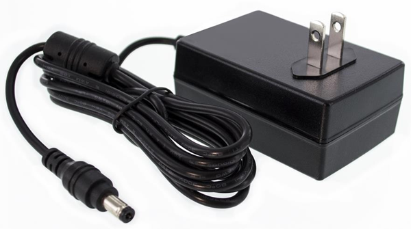
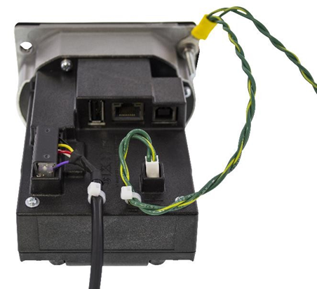
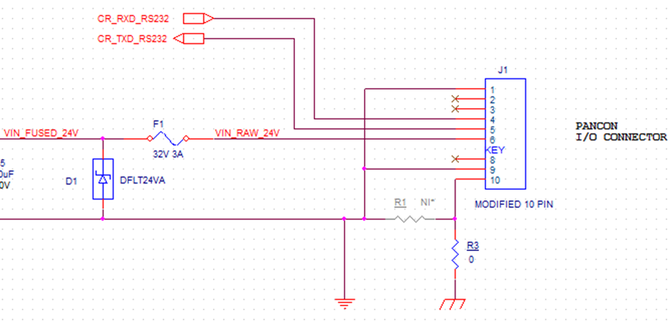
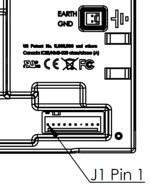
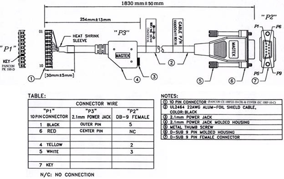
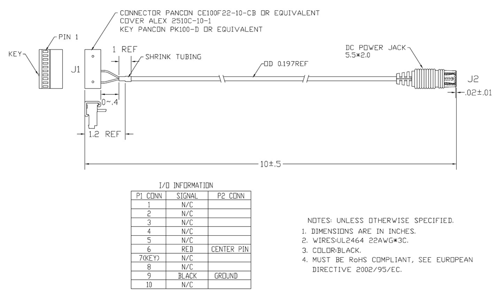
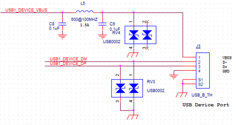
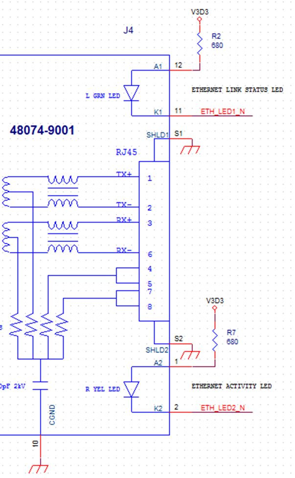

170 mA
REGISTERED TO ISO 9001:2015
MagTek I 1710 Apollo Court I Seal Beach, CA 90740 I Phone: (562) 546-6400 I Technical Support: (888) 624-8350 www.magtek.com
Copyright © 2006 - 2025 MagTek, Inc. Printed in the United States of America
INFORMATION IN THIS PUBLICATION IS SUBJECT TO CHANGE WITHOUT NOTICE AND MAY CONTAIN TECHNICAL INACCURACIES OR GRAPHICAL DISCREPANCIES. CHANGES OR IMPROVEMENTS MADE TO THIS PRODUCT WILL BE UPDATED IN THE NEXT PUBLICATION RELEASE. NO PART OF THIS DOCUMENT MAY BE REPRODUCED OR TRANSMITTED IN ANY FORM OR BY ANY MEANS, ELECTRONIC OR MECHANICAL, FOR ANY PURPOSE, WITHOUT THE EXPRESS WRITTEN PERMISSION OF MAGTEK, INC. SOME FEATURES AND FUNCTIONS MAY BE DOCUMENTED, BUT NOT AVAILABLE WITH THE CURRENT RELEASE OF THE PRODUCT. PLEASE CONTACT YOUR MAGTEK REPRESENTATIVE FOR QUESTIONS ABOUT SPECIFIC FEATURES AND FUNCTIONS AND WHEN THEY ARE SCHEDULED TO BECOME AVAILABLE.
MagTek® is a registered trademark of MagTek, Inc. MagnePrint® is a registered trademark of MagTek, Inc. MagneSafe® is a registered trademark of MagTek, Inc. Magensa™ is a trademark of MagTek, Inc.
AAMVA™ is a trademark of AAMVA.
American Express® and EXPRESSPAY FROM AMERICAN EXPRESS® are registered trademarks of American Express Marketing & Development Corp.
Apple Pay® is a registered trademark to Apple Inc.
D-PAYMENT APPLICATION SPECIFICATION® is a registered trademark to Discover Financial Services CORPORATION
MasterCard® is a registered trademark and PayPass™ and Tap & Go™ are trademarks of MasterCard International Incorporated.
Visa® and Visa payWave® are registered trademarks of Visa International Service Association.
ANSI®, the ANSI logo, and numerous other identifiers containing "ANSI" are registered trademarks, service marks, and accreditation marks of the American National Standards Institute (ANSI).
ISO® is a registered trademark of the International Organization for Standardization.
PCI Security Standards Council® is a registered trademark of the PCI Security Standards Council, LLC. EMVCo™ and EMV™ are trademarks of EMVCo and its licensors.
UL™ and the UL logo are trademarks of UL LLC.
Bluetooth® is a registered trademark of Bluetooth SIG.
iPhone®, iPod®, and Mac® are registered trademarks of Apple Inc., registered in the U.S. and other countries. App StoreSM is a service mark of Apple Inc., registered in the U.S. and other countries. iPad™ is a trademark of Apple, Inc. IOS is a trademark or registered trademark of Cisco in the U.S. and other countries and is used by Apple Inc. under license.
CRYPTERA® is a registered trademark of CRYPTERA A/S.
Microsoft® and Windows® are registered trademarks of Microsoft Corporation.
All other system names and product names are the property of their respective owners.
MagTek warrants that the products sold pursuant to this Agreement will perform in accordance with MagTek’s published specifications. This warranty shall be provided only for a period of one year from the date of the shipment of the product from MagTek (the “Warranty Period”). This warranty shall apply only to the “Buyer” (the original purchaser, unless that entity resells the product as authorized by MagTek, in which event this warranty shall apply only to the first repurchaser).
During the Warranty Period, should this product fail to conform to MagTek’s specifications, MagTek will, at its option, repair or replace this product at no additional charge except as set forth below. Repair parts and replacement products will be furnished on an exchange basis and will be either reconditioned or new. All replaced parts and products become the property of MagTek. This limited warranty does not include service to repair damage to the product resulting from accident, disaster, unreasonable use, misuse, abuse, negligence, or modification of the product not authorized by MagTek. MagTek reserves the right to examine the alleged defective goods to determine whether the warranty is applicable.
Without limiting the generality of the foregoing, MagTek specifically disclaims any liability or warranty for goods resold in other than MagTek’s original packages, and for goods modified, altered, or treated without authorization by MagTek.
Service may be obtained by delivering the product during the warranty period to MagTek (1710 Apollo Court, Seal Beach, CA 90740). If this product is delivered by mail or by an equivalent shipping carrier, the customer agrees to insure the product or assume the risk of loss or damage in transit, to prepay shipping charges to the warranty service location, and to use the original shipping container or equivalent. MagTek will return the product, prepaid, via a three (3) day shipping service. A Return Material Authorization (“RMA”) number must accompany all returns. Buyers may obtain an RMA number by contacting Technical Support at (888) 624-8350.
EACH BUYER UNDERSTANDS THAT THIS MAGTEK PRODUCT IS OFFERED AS IS. MAGTEK MAKES NO OTHER WARRANTY, EXPRESS OR IMPLIED, AND MAGTEK DISCLAIMS ANY WARRANTY OF ANY OTHER KIND, INCLUDING ANY WARRANTY OF MERCHANTABILITY OR FITNESS FOR A PARTICULAR PURPOSE.
IF THIS PRODUCT DOES NOT CONFORM TO MAGTEK’S SPECIFICATIONS, THE SOLE REMEDY SHALL BE REPAIR OR REPLACEMENT AS PROVIDED ABOVE. MAGTEK’S LIABILITY, IF ANY, SHALL IN NO EVENT EXCEED THE TOTAL AMOUNT PAID TO MAGTEK UNDER THIS AGREEMENT. IN NO EVENT WILL MAGTEK BE LIABLE TO THE BUYER FOR ANY DAMAGES, INCLUDING ANY LOST PROFITS, LOST SAVINGS, OR OTHER INCIDENTAL OR CONSEQUENTIAL DAMAGES ARISING OUT OF THE USE OF, OR INABILITY TO USE, SUCH PRODUCT, EVEN IF MAGTEK HAS BEEN ADVISED OF THE POSSIBILITY OF SUCH DAMAGES, OR FOR ANY CLAIM BY ANY OTHER PARTY.
LIMITATION ON LIABILITY
EXCEPT AS PROVIDED IN THE SECTIONS RELATING TO MAGTEK’S LIMITED WARRANTY, MAGTEK’S LIABILITY UNDER THIS AGREEMENT IS LIMITED TO THE CONTRACT PRICE OF THIS PRODUCT.
MAGTEK MAKES NO OTHER WARRANTIES WITH RESPECT TO THE PRODUCT, EXPRESSED OR IMPLIED, EXCEPT AS MAY BE STATED IN THIS AGREEMENT, AND MAGTEK DISCLAIMS ANY IMPLIED WARRANTY, INCLUDING WITHOUT LIMITATION ANY IMPLIED WARRANTY OF MERCHANTABILITY OR FITNESS FOR A PARTICULAR PURPOSE.
MAGTEK SHALL NOT BE LIABLE FOR CONTINGENT, INCIDENTAL, OR CONSEQUENTIAL DAMAGES TO PERSONS OR PROPERTY. MAGTEK FURTHER LIMITS ITS LIABILITY OF ANY KIND WITH RESPECT TO THE PRODUCT, INCLUDING ANY NEGLIGENCE ON ITS PART, TO THE CONTRACT PRICE FOR THE GOODS.
MAGTEK’S SOLE LIABILITY AND BUYER’S EXCLUSIVE REMEDIES ARE STATED IN THIS SECTION AND IN THE SECTION RELATING TO MAGTEK’S LIMITED WARRANTY.
This device complies with Part 15 of the FCC Rules. Operation is subject to the following two conditions: (1) This device may not cause harmful interference, and (2) This device must accept any interference received, including interference that may cause undesired operation.
Note: This equipment has been tested and found to comply with the limits for a Class B digital device, pursuant to part 15 of the FCC Rules. These limits are designed to provide reasonable protection against harmful interference in a residential installation. This equipment generates, uses and can radiate radio frequency energy and, if not installed and used in accordance with the instructions, may cause harmful interference to radio communications. However, there is no guarantee that interference will not occur in a particular installation. If this equipment does cause harmful interference to radio or television reception, which can be determined by turning the equipment off and on, the user is encouraged to try to correct the interference by one or more of the following measures:
· Reorient or relocate the receiving antenna.
· Increase the separation between the equipment and receiver.
· Connect the equipment into an outlet on a circuit different from that to which the receiver is connected.
· Consult the dealer or an experienced radio/TV technician for help.
Caution: Any changes or modifications not expressly approved by the party responsible for compliance could void the user’s authority to operate this equipment. RF Exposure: A distance of 20 cm shall be maintained between the antenna and users, and the transmitter may not be co-located with any other transmitter or antenna.
This product is recognized per Underwriter Laboratories and Canadian Underwriter Laboratories 1950.
This digital apparatus does not exceed the Class B limits for radio noise from digital apparatus set out in the Radio Interference Regulations of the Canadian Department of Communications.
Le présent appareil numérique n’émet pas de bruits radioélectriques dépassant les limites applicables aux appareils numériques de la classe B prescrites dans le Réglement sur le brouillage radioélectrique édicté par le ministère des Communications du Canada.
This Class B digital apparatus complies with Canadian ICES-003.
Cet appareil numérique de la classe B est conformé à la norme NMB-003 du Canada.
Testing for compliance with CE requirements was performed by an independent laboratory. The unit under test was found compliant with standards established for Class B devices.
This product is recognized per UL 60950-1, 2nd Edition, 2011-12-19 (Information Technology Equipment - Safety - Part 1: General Requirements), CSA C22.2 No. 60950-1-07, 2nd Edition, 2011-12 (Information Technology Equipment - Safety - Part 1: General Requirements).
When ordered as RoHS compliant, this product meets the Electrical and Electronic Equipment (EEE) Reduction of Hazardous Substances (RoHS) Directive (EU) 2015/863 amending Annex II to Directive 2011/65/EU. The marking is clearly recognizable, either as written words like “Pb-free,” “lead-free,” or as another clear symbol ( ).
IMPORTANT: YOU SHOULD CAREFULLY READ ALL THE TERMS, CONDITIONS AND RESTRICTIONS OF THIS LICENSE AGREEMENT BEFORE INSTALLING THE SOFTWARE PACKAGE. YOUR INSTALLATION OF THE SOFTWARE PACKAGE PRESUMES YOUR ACCEPTANCE OF THE TERMS, CONDITIONS, AND RESTRICTIONS CONTAINED IN THIS AGREEMENT. IF YOU DO NOT AGREE WITH THESE TERMS, CONDITIONS, AND RESTRICTIONS, PROMPTLY RETURN THE SOFTWARE PACKAGE AND ASSOCIATED DOCUMENTATION TO THE ADDRESS IN THIS DOCUMENT, ATTENTION: CUSTOMER SUPPORT.
TERMS, CONDITIONS, AND RESTRICTIONS
MagTek, Incorporated (the "Licensor") owns and has the right to distribute the described software and documentation, collectively referred to as the "Software."
LICENSE: Licensor grants you (the "Licensee") the right to use the Software in conjunction with MagTek products. LICENSEE MAY NOT COPY, MODIFY, OR TRANSFER THE SOFTWARE IN WHOLE OR IN PART EXCEPT AS EXPRESSLY PROVIDED IN THIS AGREEMENT. Licensee
may not decompile, disassemble, or in any other manner attempt to reverse engineer the Software. Licensee shall not tamper with, bypass, or alter any security features of the software or attempt to do so.
TRANSFER: Licensee may not transfer the Software or license to the Software to another party without the prior written authorization of the Licensor. If Licensee transfers the Software without authorization, all rights granted under this Agreement are automatically terminated.
COPYRIGHT: The Software is copyrighted. Licensee may not copy the Software except for archival purposes or to load for execution purposes. All other copies of the Software are in violation of this Agreement.
TERM: This Agreement is in effect as long as Licensee continues the use of the Software. The Licensor also reserves the right to terminate this Agreement if Licensee fails to comply with any of the terms, conditions, or restrictions contained herein. Should Licensor terminate this Agreement due to Licensee's failure to comply, Licensee agrees to return the Software to Licensor. Receipt of returned Software by the Licensor shall mark the termination.
LIMITED WARRANTY: Licensor warrants to the Licensee that the disk(s) or other media on which the Software is recorded are free from defects in material or workmanship under normal use.
THE SOFTWARE IS PROVIDED AS IS. LICENSOR MAKES NO OTHER WARRANTY OF ANY KIND, EITHER EXPRESS OR IMPLIED, INCLUDING, BUT NOT LIMITED TO, THE IMPLIED WARRANTIES OF MERCHANTABILITY AND FITNESS FOR A PARTICULAR PURPOSE.
Because of the diversity of conditions and hardware under which the Software may be used, Licensor does not warrant that the Software will meet Licensee specifications or that the operation of the Software will be uninterrupted or free of errors.
IN NO EVENT WILL LICENSOR BE LIABLE FOR ANY DAMAGES, INCLUDING ANY LOST PROFITS, LOST SAVINGS, OR OTHER INCIDENTAL OR CONSEQUENTIAL DAMAGES ARISING OUT OF THE USE, OR INABILITY TO USE THE SOFTWARE. Licensee's sole remedy in
the event of a defect in material or workmanship is expressly limited to replacement of the Software disk(s) if applicable.
GOVERNING LAW: If any provision of this Agreement is found to be unlawful, void, or unenforceable, that provision shall be removed from consideration under this Agreement and will not affect the enforceability of any of the remaining provisions. This Agreement shall be governed by the laws of the State of California and shall inure to the benefit of MagTek, Incorporated, its successors or assigns.
ACKNOWLEDGMENT: LICENSEE ACKNOWLEDGES THAT LICENSEE HAS READ THIS AGREEMENT, UNDERSTANDS ALL OF ITS TERMS, CONDITIONS, AND RESTRICTIONS, AND AGREES TO BE BOUND BY THEM. LICENSEE ALSO AGREES THAT THIS AGREEMENT SUPERSEDES ANY AND ALL VERBAL AND WRITTEN COMMUNICATIONS BETWEEN LICENSOR AND LICENSEE OR THEIR ASSIGNS RELATING TO THE SUBJECT MATTER OF THIS AGREEMENT.
QUESTIONS REGARDING THIS AGREEMENT SHOULD BE ADDRESSED IN WRITING TO MAGTEK, INCORPORATED, ATTENTION: CUSTOMER SUPPORT, AT THE ADDRESS LISTED IN THIS DOCUMENT, OR E-MAILED TO
DEMO SOFTWARE / SAMPLE CODE: Unless otherwise stated, all demo software and sample code are to be used by Licensee for demonstration purposes only and MAY NOT BE incorporated into any production or live environment. The PIN Pad sample implementation is for software PIN Pad test purposes only and is not PCI compliant. To meet PCI compliance in production or live environments, a third-party PCI compliant component (hardware or software-based) must be used.
12
Aug 31, 2017
Refresh from master rev 12 version 36 draft:
Add (sections removed in Rev 20); Update key IDs in response of Command 0x02::0x0B - Get Challenge; Remove DF50 Device State from Data Object F1 - Device Status and update Data Object DF51 Device Status; Deprecate Application Group 0x09 and move activation commands to (section removed in Rev 20); Misc. clarifications and corrections
13
Jun 14, 2018
Refresh from master rev 12 release:
Remove placeholder information about EMV L1, which device doesn’t support; Remove Command 0x08::0x01 - Pre-Activate Device; Remove Command 0x08::0x03 - Re-Activate Device; Complete rewrite of Command 0x02::0x58 - Request Device Certificate; Add Command 0x03::0x70 - Set Chip Card Support; Remove mention of fixed PIN keys, mutual authentication key, login / logout; Remove all reference to being able to read PCI Hardware ID; Clarify MSR and EMV data behavior based on device MSR Whitelist; Add Data Object DFDF0B Primitive - Message Data Information throughout; Misc. clarifications and corrections.
14
Aug 6, 2018
Refresh from master rev 13 release:
Clarify whitelist and encryption / clear text behavior throughout; Remove MagTek Custom EMV Tags Appendix and roll into complete rewrite of Appendix E; Clarify purpose / usage of Command 0x05::0x01 - Read PAN; Clean up result code list in Result Code Data Object (Tag C3); Clarify Byte 8 of Data Object F1 - Device Status; Add Appendix H Licenses and Copyright Disclosures; Misc. clarifications and corrections
Rev Number
Date
Notes
10
May 10, 2017
Initial release derived from master rev 10 release
11
Jul 5, 2017
Rev Number
Date
Notes
15
Mar 22, 2019
Refresh from master rev 15 release:
Add Notification 0x01::0x10 - Big Block Device Data, clarify response to Command 0x02::0x0E - Get Key / Certificate Information is wrapped in that construct; Add supporting details about Quick Chip function in Command 0x07::0x00 - EMV L2 Start Transaction; Add
Notification 0x07::0x8A - EMV L2 Transaction Status and clarify status reporting behavior throughout document; Add Command 0x04::0x09 - Read MSR Data; Update Command 0x07::0x10 - Modify EMV L2 Terminal Capabilities Configuration and Command 0x07::0x11 - Read EMV L2 Terminal Capabilities Configuration; Update tags 9F40 and DFDF20 in EMV Contact Terminal Settings and Defaults; Update supported languages in Terminal Language Codes; Update Notification 0x07::0x82 - EMV L2 User Selection Request; Document Command 0x07::0x0B - EMV L2 Get Kernel Base Checksum; Add EMV Configuration Security setting, MSR Unmask Service Code setting to (section removed in Rev 20); Add several customer-facing commands in Application Group 0x07 - EMV L2 Contact Messages (Chip Card L2 Mode Only); Misc. clarifications and corrections.
16
Sep 3, 2020
Rev Number
Date
Notes
20
Nov 11, 2021
Refresh from master rev 20 release:
FIRMWARE REVISION C CHANGES:
Update copyright page; Add Software License Agreement; Delete commands and other information about removal detection feature and activation, including Command 01:53 Activate Device, Command 01:60 Read Activation Log, and change byte 8 Dismount Switch status of Data Object DF51 Device Status to always show Activated; Appendix E.2.2 Table 4-145 increase number of application slots to 32; Make Command 0x00::0x16 - Get Firmware Version, Command 0x00::0x23 - Get Boot Loader Version, and Command 0x07::0x09 - EMV L2 Modify CA Public Key public; Add new Device Signing CSR/certificate options; Add Command 0x07::0x13 - EMV L2 Continue Action and Notification 0x07::0x8C - EMV L2 Continue Notification; Add Enhanced Application Selection behavior to Notification 0x07::0x82 - EMV L2 User Selection Request; Add Command 0x07::0x12
- Read EMV L2 Configuration Check Values; Migrate EMV transaction flow to stand-alone section 4.7.1; Update RoHS Statement; Throughout, add definitions for MAC calculations; Change Command 0x07::0x00 - EMV L2 Start Transaction Byte 1 definition to Reserved.
FIRMWARE REVISION D CHANGES:
Add certified EMV configurations and update configuration identifier descriptions in Command 0x07::0x10 - Modify EMV L2 Terminal Capabilities Configuration and Command 0x07::0x11 - Read EMV L2 Terminal Capabilities Configuration; Change terminal and application tags in EMV Contact Settings (Contact Only) to meet EMVCo 4.3j requirements; E.1 clarify number of available slots; For EPP integration, add Appendix G, add encrypted PAN option to Notification 0x04::0x11 - MSR Card Data Available and Command 0x05::0x01 - Read PAN and Notification 0x07::0x88 - EMV L2 Online PIN CVM Request, add Command 0x02::0x0A - EPP Pairing Certificate Exchange and Command 0x02::0x0C - EPP Pairing Load KEK and Command 0x02::0x0D - EPP Pairing Load Derivation Key, add EPP Info ID to response of Command 0x02::0x0E - Get Key / Certificate Information; For offline PIN support, add Command 0x07::0x14 - EMV L2 Offline PIN CVM Result, Notification 0x07::0x8B - EMV L2 Offline PIN CVM Request; Update output data tables in Notification 0x07::0x83 - EMV L2 ARQC Message, ARPC Response from Online Processing (EMV Only), and Transaction Result Message - Batch Data Format (EMV Only); Update and clarify Data Object F4 - Magnetic Stripe Reader Card Data; Add 2.5.1 Primitive Data Types; Misc. clarifications and corrections.
Rev Number
Date
Notes
200
August 6, 2025
Add Tags: DF34, DF35, DF36, DF37, DF38
DF40, DF41, DF43, DF52,DF53, DF54, DF55, DF56, 9F4D,
9F6E to Table 4-124 - Message Structure for Notification 0x07::0x8C - EMV L2 Continue Notification
Add new ID Option 0x04 = Vendor Config ID oDynamo-OLEP to Table 4-99 - Message Structure for Command 0x07::0x10
- Modify EMV L2 Terminal Capabilities Configuration; Revised description for Application selection Notification 0x07::0x82 - EMV L2 User Selection Request; Clarified that first menu item is index 0 - Command 0x07::0x02 - EMV L2 User Selection Result
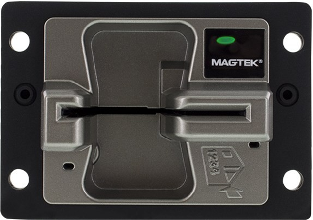
Refresh from master rev 11 release:
Update Table 1-1 - Device Features; Remove Set Factory Defaults command; Add whitelist functionality to Command 0x03::0x80 - Read PAN Whitelist / Account Data Whitelist; Update values available for (section removed Rev 20); Remove PIN and Clear Text functions from Application Group 0x04 - Magnetic Stripe Reader (MSR) Messages; Add PAN and whitelist info to Notification 0x04::0x11 - MSR Card Data Available and Command 0x05::0x01 - Read PAN; Spec changed from using a connected EPP to providing PAN to an external device, which led to removing Application Group 9 EPP Commands, adding Command 0x05::0x01 - Read PAN; Add Notification 0x07::0x88 - EMV L2 Online PIN CVM Request; Misc. clarifications and corrections.
Add POS Entry Mode and EMV Fallback tags to Data Object F4 - Magnetic Stripe Reader Card Data; Expand MSR Fallback to have automatic MSR Fallback on EMV failure based on DFDF67; Clarify mention of RSA OAEP is V2.0; Clarify using NULL in place of MAC data when issuing EMV command with MAC disabled; Correct MSR track status in tag F4; Update error code return for Command 0x07::0x06 - EMV L2 Get Contact Terminal Configuration; Update Command 0x03::0x00 - Card Latch Control response to show no C4 tag is being returned; Add Command 0x07::0x0E - EMV L2 Commit Configuration to customer documentation; Misc. clarifications and corrections.

Command 0x02::0x0A - EPP Pairing Certificate Exchange
This command starts the EPP pairing process on oDynamo using the results from the START_EXCHANGE command on the Encrypting PIN Pad (EPP). The host should use the oDynamo response as the parameters for the next EPP command GENERATE_KEK. For details about the pairing flow, see Appendix G How to Pair With a Cryptera Encrypting PIN Pad.
Tag
Len
Value(s) / Description
If an error occurs, the device will terminate the command and report the error using an ACK Response containing the result code. For a full list of error codes, see 2.4.4 Result Code Data Object (Tag C3). If no error occurs, the device responds as follows:
Command 0x02::0x0B - Get Challenge
This command directs the device to send challenge data to the host, which the host can then use to perform a specific sensitive operation / modify a specific type of device setting. Information about how the host should pass the required challenge data to the device is included in the documentation for all commands that use this security mechanism.
Upon providing the challenge to the host, the device sets an internal 5-minute countdown timer. When the time limit expires, the device will no longer accept the challenge. This binding of the command to a specific time period allows the device to detect and reject commands that have been captured/intercepted at one point in time and replayed later.
If an error occurs, the device will terminate the command and report the error using an ACK Response containing the result code. For a full list of error codes, see 2.4.4 Result Code Data Object (Tag C3). If no error occurs, the device responds as follows:
Command 0x02::0x0C - EPP Pairing Load KEK
This command is the second step in the EPP pairing process after Command 0x02::0x0A - EPP Pairing Certificate Exchange has completed successfully. This step loads a temporary key from the EPP that will be used during the third step of pairing (Command 0x02::0x0D - EPP Pairing Load Derivation Key). For details about the pairing flow, see Appendix G How to Pair With a Cryptera Encrypting PIN Pad.
If an error occurs, the device will terminate the command and report the error using an ACK Response containing the result code. For a full list of error codes, see 2.4.4 Result Code Data Object (Tag C3). If no error occurs, the device responds as follows:
Command 0x02::0x0D - EPP Pairing Load Derivation Key
This command is used for the third and final step of the EPP pairing process. It securely loads a key shared with the paired EPP. This key is used to derive keys that protect the PIN and PAN sent to/from the EPP.. For details about the pairing flow, see Appendix G How to Pair With a Cryptera Encrypting PIN Pad.
If an error occurs, the device will terminate the command and report the error using an ACK Response containing the result code. For a full list of error codes, see 2.4.4 Result Code Data Object (Tag C3). If no error occurs, the device responds as follows:
Command 0x02::0x0E - Get Key / Certificate Information
The host uses this command to get key or certificate information from the device.
If an error occurs, the device terminates the command and reports the error using an ACK Response containing the result code. For a full list of error codes, see 2.4.4 Result Code Data Object (Tag C3).
If no error occurs, the device responds by immediately sending two or more instances of Notification 0x01::0x10 - Big Block Device Data, which the host should concatenate, then interpret as follows:
Command 0x02::0x58 - Request Device Certificates
The host uses this command to request the Device Certificate, which the host would generally pass to Magensa web services that generate signed byte sequences for remote configuration commands.
If an error occurs, the device will terminate the command and report the error using an ACK Response containing the result code. For a full list of error codes, see 2.4.4 Result Code Data Object (Tag C3). If no error occurs, the device responds as follows:
The host should then wait (up to 90 seconds in some cases) for the device to respond synchronously with the requested data.
01
02
Application ID Data Object (Tag C1) = 0x02 Authentication Messages
C2
01
0B
Command ID Data Object (Tag C2) = 0x0A EPP Certificate Exchange
C3
01
00
Result Code Data Object (Tag C3) = 0x00 OK / Done
C4
Calculated
Data Field Data Object (Tag C4 or E0) =
Provide this data as the parameter portion of the EPP GENERATE_KEK command.
01
02
Application ID Data Object (Tag C1) = 0x02 Authentication Messages
C2
01
0B
Command ID Data Object (Tag C2) = 0x0B Get Challenge
C4
02
Data Field Data Object (Tag C4 or E0) = Sub Operation:
0xDF71 = MSR Initial Key for DUKPT 0xDF73 = MSR Key Loader Certificate
0xDF75 = Device Authentication Request signed by MSR Key Loader Certificate 0xDF7B = Configuration signed by MSR Key Loader Certificate
0xDF7C = Manufacturer Command
01
02
Application ID Data Object (Tag C1) = 0x02 Authentication Messages
C2
01
0B
Command ID Data Object (Tag C2) = 0x0B Get Challenge
C3
01
00
Result Code Data Object (Tag C3) = 0x00 OK / Done
E0
Calculated
Data Field Data Object (Tag C4 or E0) = Bytes 0..1 Sub Operation:
0xDF71 = MSR Initial Key for DUKPT 0xDF73 = MSR Key Loader Certificate
0xDF75 = Device Authentication Request signed by MSR Key Loader Certificate 0xDF7B = Configuration signed by MSR Key Loader Certificate
0xDF7C = Manufacturer Command
Bytes 2..13 Data Block:
8 bytes device serial number 4 bytes random token
01
02
Application ID Data Object (Tag C1) = 0x02 Authentication Messages
C2
01
0B
Command ID Data Object (Tag C2) = 0x0C Load KEK
C4
Calculated
Data Field Data Object (Tag C4 or E0) =
Use complete response from the EPP GENERATE_KEK command when the response code is OK (first 4 bytes should be 00020000).
01
02
Application ID Data Object (Tag C1) = 0x02 Authentication Messages
C2
01
0B
Command ID Data Object (Tag C2) = 0x0C Load KEK
C3
01
00
Result Code Data Object (Tag C3) = 0x00 OK / Done
01
02
Application ID Data Object (Tag C1) = 0x02 Authentication Messages
C2
01
0B
Command ID Data Object (Tag C2) = 0x0D Load Derivation Key
C4
Calculated
Data Field Data Object (Tag C4 or E0) =
EPP response to the FETCH_KEY(LINK_KGK) command if the response code was
OK starting with “B0080B0TX”
01
02
Application ID Data Object (Tag C1) = 0x02 Authentication Messages
C2
01
0B
Command ID Data Object (Tag C2) = 0x0D Load Derivation Key
C3
01
00
Result Code Data Object (Tag C3) = 0x00 OK / Done
C4
03
3 byte EPP Key KCV. This should be compared with the KCV read from the EPP to confirm that the pairing process is complete and correct.
01
02
Application ID Data Object (Tag C1) = 0x02 Authentication Messages
C2
01
0E
Command ID Data Object (Tag C2) = 0x0E Get Key / Certificate Information
C4
Calculated
Data Field Data Object (Tag C4 or E0) = Byte 0 Info ID from Table 4-49
01
02
Application ID Data Object (Tag C1) = 0x02 Authentication Messages
C2
01
0E
Command ID Data Object (Tag C2) = 0x0E Get Key / Certificate Information
C3
01
00
Result Code Data Object (Tag C3) = 0x00 OK / Done
C4
Calculated
Data Field Data Object (Tag C4 or E0) = Byte 0 Info ID from Table 4-49
Byte 1 Key Status If Info ID < 0x80
0x00 = Empty (default) 0x01 = OK
0x02 = Exhausted If Info ID = 0x80:
0x00 to 0x05 = KCV type from Table 4-49
Byte 2 Data Length corresponding to the selected Info ID and shown in Table 4-49
0x01,0x02
2
20
KSN
If no more keys
0x02
1
20
KSN
MSR key
0x04
1
calculated (<=59)
SN & subject’s
DN**
If MSR cert exists
0x07
1
Calculated (<=20)
KCV & EPP SN
length & EPP SN
Data and KCV for EPP Paired Key
0x80
kcv_type=1
4
KCV value
KCV for MSR key
0x80
kcv_type=2
4
KCV value
KCV for AMK (signed by MSR cert)
0x80
kcv_type=5
4
Hash value
Device Authentication Token signed by MSR Key Loader Certificate
01
02
Application ID Data Object (Tag C1) = 0x02 Authentication Messages
C2
01
58
Command ID Data Object (Tag C2) = 0x58 Key Handling or Manufacturer Command
E0
02
Data Field Data Object (Tag C4 or E0) =
· 0xDF6E = Request Device Certificate, or
· 0xDF72 = Request Device Signing Certificate
01
02
Application ID Data Object (Tag C1) = 0x02 Authentication Messages
C2
01
58
Command ID Data Object (Tag C2) = 0x58 Key Handling or Manufacturer Command
C3
01
00
Result Code Data Object (Tag C3) = 0x00 OK / Done
C4
Calculated
Data Field Data Object (Tag C4 or E0) =
X.509 Device certificate in DER format
C0
01
01
Message Type Data Object (Tag C0) = 0x01 Command
C1
01
02
Application ID Data Object (Tag C1) = 0x02 Authentication Messages
C2
01
0B
Command ID Data Object (Tag C2) = 0x0A EPP Certificate Exchange
C4
Calculated
Data Field Data Object (Tag C4 or E0) =
Use complete response to the EPP START_EXCHANGE command when the response code indicates OK (first 4 bytes should be 00020000).
Tag
Len
Value(s) / Description
C0
01
02
Message Type Data Object (Tag C0) = 0x02 Response
Tag
Len
Value(s) / Description
C0
01
01
Message Type Data Object (Tag C0) = 0x01 Command
Tag
Len
Value(s) / Description
C0
01
02
Message Type Data Object (Tag C0) = 0x02 Response
Tag
Len
Value(s) / Description
C0
01
01
Message Type Data Object (Tag C0) = 0x01 Command
Tag
Len
Value(s) / Description
C0
01
02
Message Type Data Object (Tag C0) = 0x02 Response
Tag
Len
Value(s) / Description
C0
01
01
Message Type Data Object (Tag C0) = 0x01 Command
Tag
Len
Value(s) / Description
C0
01
02
Message Type Data Object (Tag C0) = 0x02 Response
Tag
Len
Value(s) / Description
C0
01
01
Message Type Data Object (Tag C0) = 0x01 Command
Tag
Len
Value(s) / Description
C0
01
02
Message Type Data Object (Tag C0) = 0x02 Response
Info ID
Key Status
Data Length
Data
Description
0x00
1
Label length
AMK (Acquirer Master Key) label
Tag
Len
Value(s) / Description
C0
01
01
Message Type Data Object (Tag C0) = 0x01 Command
Tag
Len
Value(s) / Description
C0
01
02
Message Type Data Object (Tag C0) = 0x02 Response
*: lbllen = auth key’s label length
**: SN = serial number of cert
DN = distinguished names of subject or issuer of cert
Data length varies with SN and DN length; max length is 59
***: its corresponding CA cert
****: KCV = Key Check Value, where the lowest 6 digits are valid
C1
C1
C1
C1
C1
C1
C1
C1
C1
If AMK (Acquirer Master Key) exists
C1
C1
This section gives the format of the data the device uses for Notification 0x07::0x84 - EMV L2 Transaction Result.
When the card does not match any rule in the device’s Account Data Whitelist, the TLV data object contains the data defined in Table 4-126.
When the card matches one or more rules in the device’s Account Data Whitelist, the TLV data object contains the data defined in Table 4-128.
Command 0x01::0x02 - Clear Transaction Data
The host uses this command to direct the device to clear all transaction data, including account data, encrypted PIN block, PAN, and amount, and return to the idle state.
Tag
Len
Value(s) / Description
If an error occurs, the device will terminate the command and report the error using an ACK Response containing the result code. For a full list of error codes, see 2.4.4 Result Code Data Object (Tag C3). If no error occurs, the device responds as follows:
Command 0x01::0xFF - Device Reset
The host uses this command to direct the device to reset.
If an error occurs, the device will terminate the command and report the error using an ACK Response containing the result code. For a full list of error codes, see 2.4.4 Result Code Data Object (Tag C3). If no error occurs, the device responds as follows:
Notification 0x01::0xFF - Device Reset
The device sends this notification to the host to notify the host that it is about to perform a periodic automatic device reset, which it initiates after 23 hours of continuous operation to fulfill PCI requirements. MagTek recommends the host software pre-empt these automatic resets by initiating resets in advance of the 23 hour schedule, at times that are least disruptive to the solution design.
Command 0x01::0x04 - Get Device Status
The host uses this command to request the device status, such as Session State, Device State, and Status.
If an error occurs, the device will terminate the command and report the error using an ACK Response containing the result code. For a full list of error codes, see 2.4.4 Result Code Data Object (Tag C3). If no error occurs, the device responds as follows:
Notification 0x01::0x04 - Send Device Status
In addition to sending device status in response to Command 0x01::0x04 - Get Device Status, the device will automatically send the same data when the device powers up, restarts, or changes state.
Command 0x01::0x10 - Send Big Block Command
The host uses this command to send command messages to the device as a sequence of packets. The host should follow this sequence:
In local memory, compose the entire command message as documented by the desired command’s usage table (for example, Command 0x01::0x17 - Update Firmware).
Calculate the length of the fully-composed command message. Divide the fully-composed command message into packets that are shorter than the connection type’s maximum packet size.
When using the USB connection, the maximum packet size is 0x3F bytes.
For every packet the host sends, if an error occurs (such as an out of order packet), the device will terminate the command, report the error using an ACK Response containing the result code, and will stop expecting to receive subsequent big block packets. The host should stop sending them. For a full list of error codes, see 2.4.4 Result Code Data Object (Tag C3).
If no error occurs, the device responds to every packet as follows:
Notification 0x01::0x10 - Big Block Device Data
The device uses this notification to send data to the host as a sequence of packets. The host should process this notification as follows:
The host may receive this notification completely unsolicited or in response to a command (all commands that operate in this way say so in the command documentation). If the host has sent such a command to the device, it should start a timeout counter and begin listening for incoming notifications.
Parse the first incoming notification, which should be identified as Packet 0000, according to Table 4-32 below. Use the value of Total Message Length to allocate buffer space to begin concatenating all subsequent packets, which together form the complete message.
Continue receiving packets 0001 through nnnn, parsing them according to Table 4-33 below, concatenating the Packet Data from all notifications in order and adding the length of Packet Data in each packet, until the length of concatenated message data equals the Total Message Length.
Command 0x01::0x17 - Update Firmware
The host uses this command to update the device’s firmware. The host should first compose the entire message for this command, then transmit the entire message to the device in packets using Command 0x01::0x10 - Send Big Block Command.
After the device receives the final packet of this command, the device will validate the firmware image, and if the validation passes, it will commit the image to the selected firmware storage location. In all cases, the device will also send an additional response:
Although this command works on all connection types, for speed reasons, MagTek recommends using an
Ethernet or USB connection to upgrade the device’s firmware.
Notification 0x01::0x40 - Card Detected / Identified / Removed
The device uses this notification to signal to the host that a cardholder has inserted or removed a card, and to identify the type of card. Upon insertion or removal of a card, the device sends this notification to provide a Card Present Indication (CPI). After the device finishes identifying the type of card, it sends this notification again to provide an ICC Present Indication (IPI). When the CPI indicates a card is present and the IPI reports it is a chip card, the host is free to begin an EMV transaction, or in the case of magnetic stripe cards, to prompt the cardholder to remove the card to swipe on exit.
Command 0x01::0x50 - Subscribe to Notifications
The host uses this command to specify which notifications the device should send to it (for example, Notification 0x01::0xFF - Device Reset). By default, the device does not send any notifications to the host.
01
01
Application ID Data Object (Tag C1) = 0x01 General Messages
C2
01
02
Command ID Data Object (Tag C2) = 0x02 Clear Transaction Data
C3
01
00
Result Code Data Object (Tag C3) = OK / Done
01
01
Application ID Data Object (Tag C1) = 0x01 General Messages
C2
01
FF
Command ID Data Object (Tag C2) = 0xFF Device Reset
01
01
Application ID Data Object (Tag C1) = 0x01 General Messages
C2
01
FF
Command ID Data Object (Tag C2) = 0xFF Device Reset
C3
01
00
Result Code Data Object (Tag C3) = OK / Done
01
01
Application ID Data Object (Tag C1) = 0x01 General Messages
C2
01
FF
Command ID Data Object (Tag C2) = 0xFF Device Reset
01
01
Application ID Data Object (Tag C1) = 0x01 General Messages
C2
01
04
Command ID Data Object (Tag C2) = 0x04 Get Device Status
01
01
Application ID Data Object (Tag C1) = 0x01 General Messages
C2
01
04
Command ID Data Object (Tag C2) = 0x04 Get Device Status
C3
01
00
Result Code Data Object (Tag C3) = OK / Done
E0
Calculated
Data Field Data Object (Tag C4 or E0) =
Data Object F1 - Device Status
01
01
Application ID Data Object (Tag C1) = 0x01 General Messages
C2
01
04
Command ID Data Object (Tag C2) = 0x04 Get Device Status
C3
01
00
Result Code Data Object (Tag C3) = OK / Done
E0
Calculated
Data Field Data Object (Tag C4 or E0) =
Data Object F1 - Device Status
When using the Ethernet connection, the maximum packet size is 0x0400 bytes.
When using a serial connection, the maximum packet size is 0x0400 bytes.
Send command 0x01::0x10 to the device as “Packet 0.” Packet 0 is short and sets up how much data the device should expect across the whole big block operation. The C4 data object can be of varying length, and its value should be a 2-byte Packet Number equal to 00 00, plus a 2-byte Packet Length, plus Packet Data containing the Total Command Message Length, in bytes, the device should expect to receive when concatenating all subsequent packets (see Table 4-29).
Wait to receive a response from the device (see Table 4-31).
Continue sending Command 0x01::0x10 to send Packets 1 through n, incrementing the Packet Number by 1 each time, until the host has sent the fully-composed command message. After sending each packet, wait for the device’s response to reduce risk of packets arriving out of order. The C4 data object for packets 1 through n can be of varying length, and its value should be a 2-byte Packet Number that increments with each call to this command, plus a 2-byte Packet Data Length, plus the Packet Data (see Table 4-30).
Listen for a final response from the device acknowledging the completed command. This means after sending the final packet, the host should expect to receive two responses: One for the final packet sent with Command 0x01::0x10, and one after the device has finished processing all the uploaded data and responds to the fully-composed command message the host has sent (for example, Command 0x01::0x17 - Update Firmware).
01
01
Application ID Data Object (Tag C1) = 0x01 General Messages
C2
01
10
Command ID Data Object (Tag C2) = 0x10 Send Big Block Command Message
C4
Calculated
Data Field Data Object (Tag C4 or E0) = 2-byte Packet Number = 00 00
2-byte Packet Data Length, LSB first
Packet Data = Total Command Message Length in bytes the device is sending using big block packets, LSB first
01
01
Application ID Data Object (Tag C1) = 0x01 General Messages
C2
01
10
Command ID Data Object (Tag C2) = 0x10 Send Big Block Command Message
C4
Calculated
Data Field Data Object (Tag C4 or E0) = 2-byte Packet Number, LSB first
2-byte Packet Data Length, LSB first Packet Data, LSB first
01
01
Application ID Data Object (Tag C1) = 0x01 General Messages
C2
01
10
Command ID Data Object (Tag C2) = 0x10 Send Big Block Command Message
C3
01
00
Result Code Data Object (Tag C3) = OK / Done
If the complete message is a notification type, the host should parse it according to the notification’s documentation. If it is a response type, the host should parse it according to the corresponding command’s response table.
01
01
Application ID Data Object (Tag C1) = 0x01 General Messages
C2
01
10
Command ID Data Object (Tag C2) = 0x10 Big Block Device Data
C4
08
Data Field Data Object (Tag C4 or E0) = 2-byte Packet Number = 00 00
2-byte Packet Data Length, LSB first
4-byte Total Message Length in bytes, LSB first
01
01
Application ID Data Object (Tag C1) = 0x01 General Messages
C2
01
10
Command ID Data Object (Tag C2) = 0x10 Big Block Device Data
C4
Calculated
Data Field Data Object (Tag C4 or E0) = 2-byte Packet Number, LSB first
2-byte Packet Data Length, LSB first Packet Data
01
01
Application ID Data Object (Tag C1) = 0x01 General Messages
C2
01
17
Command ID Data Object (Tag C2) = 0x17 Update Firmware
C4
Calculated
Data Field Data Object (Tag C4 or E0) = Byte 1 Subcommand
0x01 = Update boot loader 0x02 = Reserved
0x03 = Update firmware image 0x04 = Reserved
Bytes 2..n: Firmware image binary data
01
01
Application ID Data Object (Tag C1) = 0x01 General Messages
C2
01
17
Command ID Data Object (Tag C2) = 0x17 Update Firmware
C3
01
Result Code Data Object (Tag C3): 0x00 = Update successful
0x01 = Invalid firmware image loaded in buffer 0x02 = Signature error
0x03 = Build version error 0x09 = Other error
01
01
Application ID Data Object (Tag C1) = 0x01 General Messages
C2
01
40
Command ID Data Object (Tag C2) = 0x40 Card Inserted/Identified/Removed
C4
02
Data Field Data Object (Tag C4 or E0) = Byte 0: Card Present Indication (CPI)
· 0x00 = Card was present and has been removed
· 0x01 = Card was not present and is now present
Byte 1: Card Type Present Indication (IPI)
· 0x00 = Card is not a chip card (ICC card)
· 0x01 = Card is a chip card (ICC card)
01
01
Application ID Data Object (Tag C1) = 0x01 General Messages
C2
01
50
Command ID Data Object (Tag C2) = 0x50 Subscribe to Notifications
C4
Calculated
Data Field Data Object (Tag C4 or E0) = Byte 0 Subscribe or Unsubscribe
0x01 = Subscribe 0x02 = Unsubscribe
Byte 1 Notifications to Subscribe To
0x00 = Subscribe/unsubscribe to all notifications 0x01 = Subscribe/unsubscribe to specific notifications
If Notifications to Subscribe To = 0x01:
Bytes 2..n contain a list of two-byte notification IDs which specify the Application Group and Notification Number of each Notification the device should send to the host. For example, to subscribe to Notification 0x01::0xFF - Device Reset, the host would include 0x010F as two bytes in the list.
01
01
Application ID Data Object (Tag C1) = 0x01 General Messages
C2
01
50
Command ID Data Object (Tag C2) = 0x50 Subscribe to Notifications
C3
01
Result Code Data Object (Tag C3)
C0
01
01
Message Type Data Object (Tag C0) = 0x01 Command
C1
01
01
Application ID Data Object (Tag C1) = 0x01 General Messages
C2
01
02
Command ID Data Object (Tag C2) = 0x02 Clear Transaction Data
Tag
Len
Value(s) / Description
C0
01
02
Message Type Data Object (Tag C0) = 0x02 Response
Tag
Len
Value(s) / Description
C0
01
01
Message Type Data Object (Tag C0) = 0x01 Command
Tag
Len
Value(s) / Description
C0
01
02
Message Type Data Object (Tag C0) = 0x02 Response
Tag
Len
Value(s) / Description
C0
01
03
Message Type Data Object (Tag C0) = 0x03 Notification
Tag
Len
Value(s) / Description
C0
01
01
Message Type Data Object (Tag C0) = 0x01 Command
Tag
Len
Value(s) / Description
C0
01
02
Message Type Data Object (Tag C0) = 0x02 Response
Tag
Len
Value(s) / Description
C0
01
03
Message Type Data Object (Tag C0) = 0x03 Notification
Tag
Len
Value(s) / Description
C0
01
01
Message Type Data Object (Tag C0) = 0x01 Command
Tag
Len
Value(s) / Description
C0
01
01
Message Type Data Object (Tag C0) = 0x01 Command
Tag
Len
Value(s) / Description
C0
01
02
Message Type Data Object (Tag C0) = 0x02 Response
Tag
Len
Value(s) / Description
C0
01
01
Message Type Data Object (Tag C0) = 0x03 Notification
Tag
Len
Value(s) / Description
C0
01
03
Message Type Data Object (Tag C0) = 0x03 Notification
Tag
Len
Value(s) / Description
C0
01
01
Message Type Data Object (Tag C0) = 0x01 Command
Tag
Len
Value(s) / Description
C0
01
02
Message Type Data Object (Tag C0) = 0x02 Response
Tag
Len
Value(s) / Description
C0
01
03
Message Type Data Object (Tag C0) = 0x03 Notification
Tag
Len
Value(s) / Description
C0
01
01
Message Type Data Object (Tag C0) = 0x01 Command
Tag
Len
Value(s) / Description
C0
01
02
Message Type Data Object (Tag C0) = 0x02 Response
C1
C1
C1
C1
C1
C1
C1
C1
C1
C1
C1
C1
C1
C1
C1
C1
C1
/DFDF0B
03
Message Data Information Byte 0 Data Type
· 0x00 = Reserved
· 0x01 = EMV Contact L2 Data
Byte 1 Encryption
· 0x00 = Data is encrypted
· 0x00 = Data is clear Text
Byte 2 - Reserved
B
R
/DFDF54
var
MAC KSN
B
R
/DFDF55
01
MAC Encryption Type
· 0xxx xxxx = Fixed Key (Not used)
· 1xxx xxxx = DUKPT Key
· xx00 xxxx = TDES
· xx01 xxxx = AES128
· xx10 xxxx = AES 256
· xxxx xx00 = Data Variant
· xxxx xx01 = PIN Variant
· xxxx xx10 = MAC Variant
B
R
/DFDF25
var
Device Serial Number (IFD Serial Number)
B
R
/FA
var
Container for generic data
T
R
//F0
var
Transaction Results
T
R
///F1
var
Container for Status Data
T
R
////DFDF1 A
01
Transaction Status
· 0x00 = Approved
· 0x01 = Declined
· 0x02 = Error
· 0x10 = Canceled by Host
· 0x1E = Manual Selection Canceled by Host
· 0x1F = Mnanual Selection Timeout
B
R
///F8
var
Container for Encrypted Data
T
R
////DFDF59
var
Encrypted Data Primitive
Decrypt the value of this TLV data object using the algorithm and variant specified in the Encrypted Transaction Data KSN (DFDF56) parameter and the Encrypted Transaction Data Encryption Type (DFDF57) parameter to read its contents. See Table 4-127 for the data structure as it should appear after decryption.
B
R
////DFDF56
var
Encrypted Transaction Data KSN
B
R
////DFDF57
01
Encrypted Transaction Data Encryption Type
· 0xxx xxxx = Fixed Key (Not used)
· 1xxx xxxx = DUKPT Key
· xx00 xxxx = TDES
· xx01 xxxx = AES128
· xx10 xxxx = AES 256
· xxxx xx00 = Data Variant
· xxxx xx01 = PIN Variant
· xxxx xx10 = MAC Variant
B
R
////DFDF58
01
Number of Padding Bytes
Number of bytes added to DFDF59 value to force its length to a multiple of 8 bytes.
B
R
///F7
var
Container for Merchant Data
T
R
////5F25
03
Application Effective Date
N
O
////5F24
03
Application Expiration Date
N
O
////5F2A
02
Transaction Currency Code
N
R
////9F02
06
Amount Authorized, numeric
N
R
////9F03
06
Amount Other, numeric
N
O
////9F06
var
Application AID
B
O
////9F12
var
Application Preferred Name
AN
O
////9F1C
08
Teminal ID
AN
O
////9F39
01
POS Entry Mode
B
O
////9C
01
Transaction Type
B
O
////9F34
03
CVM Results
B
O
////5F57
01
Account Type
B
O
O
////DFDF4 D
var
Masked Track 2 ICC Data
AN
O
R
/DF4F
var
Issuer Script Results
B
O
/DF8120
05
Terminal Action Code - Default
For a list of possible values, see EMV 4.3 Book 3 values for TLV object 95 Terminal Verification Results.
B
O
/DF8121
05
Terminal Action Code - Denial
For a list of possible values, see EMV 4.3 Book 3 values for TLV object 95 Terminal Verification Results.
B
O
/DF8122
05
Terminal Action Code - Online
For a list of possible values, see EMV 4.3 Book 3 values for TLV object 95 Terminal Verification Results.
B
O
/F4
var
Container for encrypted MSR data
See Data Object F4 - Magnetic Stripe Reader Card Data for details
T
O
/F5
var
Container for encrypted PIN Data
T
O
//99
var
Encrypted PIN Block Data
B
O
//DFDF41
var
Encrypted PIN Block KSN
B
O
//DFDF42
var
PIN Block Encryption Type
· 0xxx xxxx = Fixed Key (Not used)
· 1xxx xxxx = DUKPT Key
· xx00 xxxx = TDES
· xx01 xxxx = AES128
· xx10 xxxx = AES 256
· xxxx xx00 = Data Variant
· xxxx xx01 = PIN Variant xxxx xx10 = MAC Variant
B
O
R
/DFDF0B
03
Message Data Information Byte 0 Data Type
· 0x00 = Reserved
· 0x01 = EMV Contact L2 Data
Byte 1 Encryption
· 0x00 = Data is encrypted
· 0x00 = Data is clear Text
Byte 2 - Reserved
B
R
/DFDF54
var
MAC KSN
B
R
/DFDF55
01
MAC Encryption Type
· 0xxx xxxx = Fixed Key (Not used)
· 1xxx xxxx = DUKPT Key
· xx00 xxxx = TDES
· xx01 xxxx = AES128
· xx10 xxxx = AES 256
· xxxx xx00 = Data Variant
· xxxx xx01 = PIN Variant
· xxxx xx10 = MAC Variant
B
R
/DFDF25
var
Device Serial Number (IFD Serial Number)
B
R
/FA
var
Container for generic data
T
R
//F0
var
Transaction Results
T
R
///F1
var
Container for Status Data
T
R
////DFDF1 A
01
Transaction Status
· 0x00 = Approved
· 0x01 = Declined
· 0x02 = Error
· 0x10 = Canceled by Host
· 0x1E = Manual Selection Canceled by Host
· 0x1F = Mnanual Selection Timeout
· 0x21 = Waiting for Card, Canceled by Host
· 0x22 = Waiting for Card, Timeout
B
R
R
////var
var
List of Data Objects configured by terminal setting DFDF17 that can reported in the transaction
///F3
var
Container for Reversal Data
T
O
////var
var
List of Data Objects configured by terminal setting DFDF05 that can reported in the transaction
///F7
var
Container for Merchant Data
T
R
////5F25
03
Application Effective Date
N
O
////5F24
03
Application Expiration Date
N
O
////5F2A
02
Transaction Currency Code
N
R
////9F02
06
Amount Authorized, numeric
N
R
////9F03
06
Amount Other, numeric
N
O
////9F06
var
Application AID
B
O
////9F12
var
Application Preferred Name
AN
O
////9F1C
08
Teminal ID
AN
O
////9F39
01
POS Entry Mode
B
O
////9C
01
Transaction Type
B
O
////9F34
03
CVM Results
B
O
////5F57
01
Account Type
B
O
////5F20
var
Cardholder Name
AN
O
////DFDF4 D
var
Masked Track 2 ICC Data
AN
O
Tag
Len
Value / Description
Typ
Req
Default
F9
var
Container for MAC structure and generic data
T
R
Tag
Len
Value / Description
Typ
Req
Default
· 0x21 = Waiting for Card, Canceled by Host
· 0x22 = Waiting for Card, Timeout
· 0x23 = Canceled by Card Swipe
· 0xFF = Unknown
Tag
Len
Value / Description
Typ
Req
Default
////5F20
var
Cardholder Name
Tag
Len
Value / Description
Typ
Req
Default
FC
var
Decrypted Data Container
Inside this container, the device inserts all EMV TLV data objects configured by TLV data object DFDF17 in EMV Contact Terminal Settings and Defaults. For definitions of possible values for standard EMV TLV data objects, see EMV 4.3 Book 3. MagTek custom TLV data objects not defined in that specification are defined in the following rows of this table.
Tag
Len
Value / Description
Typ
Req
Default
F9
var
Container for MAC structure and generic data
Tag
Len
Value / Description
Typ
Req
Default
///F2
var
Container for Batch Data
Padding to ensure the length of data, starting with the message length at the very beginning, and ending with any additional padding, is a multiple of 8 bytes. This is a requirement of using the CBC-MAC algorithm.
Four byte CBC-MAC. Four byte CBC-MAC. To calculate the MAC include the F9 tag, length, and contents, and pad it with zeroes to make overall length a multiple of 8. Use the DUKPT MAC variant of the transaction key (DUKPT MAC variant constant = 0000 0000 0000 FF00 0000 0000 0000 FF00) with the CBC-MAC algorithm, and use the first 4 bytes of the 8.
Padding to force DFDF59 plus padding to be a multiple of 8 bytes
Padding to ensure the length of data, starting with the message length at the very beginning, and ending with any additional padding, is a multiple of 8 bytes. This is a requirement of using the CBC-MAC algorithm.
Four byte CBC-MAC. To calculate the MAC include the F9 tag, length, and contents, and pad it with zeroes to make overall length a multiple of 8. Use the DUKPT MAC variant of the transaction key (DUKPT MAC variant constant = 0000 0000 0000 FF00 0000 0000 0000 FF00) with the CBC-MAC algorithm, and use the first 4 bytes of the 8.
AN
T
T
T
· 0x23 = Canceled by Card Swipe
· 0xFF = Unknown
This section documents the full set of messages that can be exchanged between the device and the host.
Command 0x00:0x10 - Get Product ID
The host uses this command to get the device’s product ID.
Table 4-1 - Message Structure for Command 0x00:0x10 - Get Product ID
Tag
Len
If an error occurs, the device will terminate the command and report the error using an ACK Response containing the result code. For a full list of error codes, see 2.4.4 Result Code Data Object (Tag C3). If no error occurs, the device responds as follows:
Command 0x00::0x12 - Get Capability String
The host uses this command to get the device’s Capability String.
If an error occurs, the device will terminate the command and report the error using an ACK Response containing the result code. For a full list of error codes, see 2.4.4 Result Code Data Object (Tag C3). If no error occurs, the device responds as follows:
Command 0x00::0x13 - Get Manufacturer
The host uses this command to get the device manufacturer.
If an error occurs, the device will terminate the command and report the error using an ACK Response containing the result code. For a full list of error codes, see 2.4.4 Result Code Data Object (Tag C3). If no error occurs, the device responds as follows:
Command 0x00::0x14 - Get Product Name
The host uses this command to get the device’s product name.
If an error occurs, the device will terminate the command and report the error using an ACK Response containing the result code. For a full list of error codes, see 2.4.4 Result Code Data Object (Tag C3). If no error occurs, the device responds as follows:
Command 0x00::0x15 - Get Secure Tracking Number
The host uses this command to get the device’s secure tracking number.
If an error occurs, the device will terminate the command and report the error using an ACK Response containing the result code. For a full list of error codes, see 2.4.4 Result Code Data Object (Tag C3). If no error occurs, the device responds as follows:
Command 0x00::0x16 - Get Firmware Version
The host uses this command to get the device’s firmware version.
If an error occurs, the device will terminate the command and report the error using an ACK Response containing the result code. For a full list of error codes, see 2.4.4 Result Code Data Object (Tag C3). If no error occurs, the device responds as follows:
Command 0x00::0x18 - Get Network Information (Ethernet Only)
The host uses this command to get information about the device’s network connection.
If an error occurs, the device will terminate the command and report the error using an ACK Response containing the result code. For a full list of error codes, see 2.4.4 Result Code Data Object (Tag C3). If no error occurs, the device responds as follows:
Command 0x00::0x23 - Get Boot Loader Version
The host uses this command to get the device’s boot loader version.
If an error occurs, the device will terminate the command and report the error using an ACK Response containing the result code. For a full list of error codes, see 2.4.4 Result Code Data Object (Tag C3). If no error occurs, the device responds as follows:
Command 0x00::0x27 - Get CT-L2 Version
The host uses this command to get the device’s EMV L2 version, if any.
If an error occurs, the device will terminate the command and report the error using an ACK Response containing the result code. For a full list of error codes, see 2.4.4 Result Code Data Object (Tag C3). If no error occurs, the device responds as follows:
Command 0x00::0x28 - Get Serial Number
The host uses this command to get the device’s serial number.
If an error occurs, the device will terminate the command and report the error using an ACK Response containing the result code. For a full list of error codes, see 2.4.4 Result Code Data Object (Tag C3). If no error occurs, the device responds as follows:
01
00
Application ID Data Object (Tag C1) = 0x00 Device Information
C2
01
10
Command ID Data Object (Tag C2) = 0x10 Get Product ID
C3
01
00
Result Code Data Object (Tag C3) = 0x00 OK / Done
C4
Calculated
Data Field Data Object (Tag C4 or E0) = Product ID, e.g., 5999
01
00
Application ID Data Object (Tag C1) = 0x00 Device Information
C2
01
12
Command ID Data Object (Tag C2) = 0x12 Get Capability String
01
00
Application ID Data Object (Tag C1) = 0x00 Device Information
C2
01
12
Command ID Data Object (Tag C2) = 0x12 Get Capability String
C3
01
00
Result Code Data Object (Tag C3) = 0x00 OK / Done
C4
Calculated
Data Field Data Object (Tag C4 or E0) =
Null-terminated string similar to
“V=1,SC=1,SR=1,TR=1,MS2=1,PFK=1,UDE=2,CE=2,CLE=1,DR=1” where each of
the comma-separated name-value pairs represents a device capability:
V = Device Version
SC = Signature Capture Support, 1=Supported, 0=Not Supported SR = SRED, 1=SRED, 0=NON-SRED
TR = Token Reversal Support, 1=Supported, 0=Not Supported MS2 = MagneSafe 2.0 Support, 1=Supported, 0=Not Supported PFK = PIN Fixed Key Support, 1=Supported, 0=Not Supported
UDE = User Data Entry Mode, 1=Encrypted Only, 2=Clear Text and Encrypted CE = Contact EMV Level Support, 1=L1, 2=L2
01
00
Application ID Data Object (Tag C1) = 0x00 Device Information
C2
01
13
Command ID Data Object (Tag C2) = 0x13 Get Manufacturer
01
00
Application ID Data Object (Tag C1) = 0x00 Device Information
C2
01
13
Command ID Data Object (Tag C2) = 0x13 Get Manufacturer
C3
01
00
Result Code Data Object (Tag C3) = 0x00 OK / Done
C4
Calculated
Data Field Data Object (Tag C4 or E0) = Manufacturer, e.g., MagTek, Inc.
01
00
Application ID Data Object (Tag C1) = 0x00 Device Information
C2
01
14
Command ID Data Object (Tag C2) = 0x14 Get Product Name
01
00
Application ID Data Object (Tag C1) = 0x00 Device Information
C2
01
14
Command ID Data Object (Tag C2) = 0x14 Get Product Name
C3
01
00
Result Code Data Object (Tag C3) = 0x00 OK / Done
C4
Calculated
Data Field Data Object (Tag C4 or E0) = Product Name, e.g., oDynamo
01
00
Application ID Data Object (Tag C1) = 0x00 Device Information
C2
01
15
Command ID Data Object (Tag C2) = 0x15 Get Secure Tracking Number
01
00
Application ID Data Object (Tag C1) = 0x00 Device Information
C2
01
15
Command ID Data Object (Tag C2) = 0x15 Get Secure Tracking Number
C3
01
00
Result Code Data Object (Tag C3) = 0x00 OK / Done
C4
26
Data Field Data Object (Tag C4 or E0) = Bytes 0..25 Secure Tracking Number
ASCII string. Example “B55984678901234567890123456”
01
00
Application ID Data Object (Tag C1) = 0x00 Device Information
C2
01
16
Command ID Data Object (Tag C2) = 0x16 Get Firmware Version
01
00
Application ID Data Object (Tag C1) = 0x00 Device Information
C2
01
16
Command ID Data Object (Tag C2) = 0x16 Get Firmware Version
C3
01
00
Result Code Data Object (Tag C3) = 0x00 OK / Done
C4
Calculated
Data Field Data Object (Tag C4 or E0) = Firmware Version, e.g., 1000004854-B1-PCI
01
00
Application ID Data Object (Tag C1) = 0x00 Device Information
C2
01
18
Command ID Data Object (Tag C2) = 0x18 Get Network Information
C4
01
Data Field Data Object (Tag C4 or E0) = Type of Information
0x00 = Request Ethernet MAC Address 0x01 = Request Ethernet IP Address
01
00
Application ID Data Object (Tag C1) = 0x00 Device Information
C2
01
18
Command ID Data Object (Tag C2) = 0x18 Get Network Informations
C3
01
00
Result Code Data Object (Tag C3) = 0x00 OK / Done
C4
Calculated
Data Field Data Object (Tag C4 or E0) = Byte 0 Type of Information
0x00 = Ethernet MAC Address 0x01 = Ethernet IP Address
Bytes 1..n.Network Information String
MAC Address in ASCII format, e.g., 112233445566 or IP Address e.g., 111.222.333.444
01
00
Application ID Data Object (Tag C1) = 0x00 Device Information
C2
01
23
Command ID Data Object (Tag C2) = 0x23 Get Boot Loader Version
01
00
Application ID Data Object (Tag C1) = 0x00 Device Information
C2
01
23
Command ID Data Object (Tag C2) = 0x23 Get Boot Loader Version
C3
01
00
Result Code Data Object (Tag C3) = 0x00 OK / Done
C4
Calculated
Data Field Data Object (Tag C4 or E0) = Boot loader version, e.g., 1000004194-A0-PCI
01
00
Application ID Data Object (Tag C1) = 0x00 Device Information
C2
01
27
Command ID Data Object (Tag C2) = 0x27 Get CT-L2 Version
01
00
Application ID Data Object (Tag C1) = 0x00 Device Information
C2
01
27
Command ID Data Object (Tag C2) = 0x27 Get CT-L2 Version
C3
01
00
Result Code Data Object (Tag C3) = 0x00 OK / Done
C4
Calculated
Data Field Data Object (Tag C4 or E0) =
ASCII string containing version info. For example “JIBE EMV L2 4.3j Version C”
01
00
Application ID Data Object (Tag C1) = 0x00 Device Information
C2
01
28
Command ID Data Object (Tag C2) = 0x28 Get Serial Number
01
00
Application ID Data Object (Tag C1) = 0x00 Device Information
C2
01
28
Command ID Data Object (Tag C2) = 0x28 Get Serial Number
C3
01
00
Result Code Data Object (Tag C3) = 0x00 OK / Done
C4
10
Data Field Data Object (Tag C4 or E0) =
Serial Number is 16 bytes long in ASCII., e.g., “1111000050123456”
Value(s) / Description
C0
01
01
Message Type Data Object (Tag C0) = 0x01 Command
C1
01
00
Application ID Data Object (Tag C1) = 0x00 Device Information
C2
01
10
Command ID Data Object (Tag C2) = 0x10 Get Product ID
Tag
Len
Value(s) / Description
C0
01
02
Message Type Data Object (Tag C0) = 0x02 Response
Tag
Len
Value(s) / Description
C0
01
01
Message Type Data Object (Tag C0) = 0x01 Command
Tag
Len
Value(s) / Description
C0
01
02
Message Type Data Object (Tag C0) = 0x02 Response
Tag
Len
Value(s) / Description
C0
01
01
Message Type Data Object (Tag C0) = 0x01 Command
Tag
Len
Value(s) / Description
C0
01
02
Message Type Data Object (Tag C0) = 0x02 Response
Tag
Len
Value(s) / Description
C0
01
01
Message Type Data Object (Tag C0) = 0x01 Command
Tag
Len
Value(s) / Description
C0
01
02
Message Type Data Object (Tag C0) = 0x02 Response
Tag
Len
Value(s) / Description
C0
01
01
Message Type Data Object (Tag C0) = 0x01 Command
Tag
Len
Value(s) / Description
C0
01
02
Message Type Data Object (Tag C0) = 0x02 Response
Tag
Len
Value(s) / Description
C0
01
01
Message Type Data Object (Tag C0) = 0x01 Command
Tag
Len
Value(s) / Description
C0
01
02
Message Type Data Object (Tag C0) = 0x02 Response
Tag
Len
Value(s) / Description
C0
01
01
Message Type Data Object (Tag C0) = 0x01 Command
Tag
Len
Value(s) / Description
C0
01
02
Message Type Data Object (Tag C0) = 0x02 Response
Tag
Len
Value(s) / Description
C0
01
01
Message Type Data Object (Tag C0) = 0x01 Command
Tag
Len
Value(s) / Description
C0
01
02
Message Type Data Object (Tag C0) = 0x02 Response
Tag
Len
Value(s) / Description
C0
01
01
Message Type Data Object (Tag C0) = 0x01 Command
Tag
Len
Value(s) / Description
C0
01
02
Message Type Data Object (Tag C0) = 0x02 Response
Tag
Len
Value(s) / Description
C0
01
01
Message Type Data Object (Tag C0) = 0x01 Command
Tag
Len
Value(s) / Description
C0
01
02
Message Type Data Object (Tag C0) = 0x02 Response
C1
C1
C1
C1
C1
C1
C1
C1
C1
C1
C1
C1
C1
C1
C1
C1
C1
C1
C1
CLE = Contactless EMV Level Support, 0=Not Supported,1=L1, 2=L2 DR = Delayed Response Support, 1=Supported, 0=Not Supported SIGN = Device Signing Certificate support, 1=Supported
The host and the device communicate with each other by exchanging blocks of data called Messages, which can be either Commands, Responses to commands, or Notifications. For example, the host may send a command to the device to change a configuration setting, and the device may send a response that the command was successful; when a cardholder inserts a card, the device may send a notification to the host that a cardholder has initiated a transaction.
The device can only service one command at a time, and sends each response within a pre-determined finite amount of time after receiving the command. After sending a command, the host must wait until the device returns a response before sending another command.
The device sends notifications to the host if the device’s state changes or if an external event occurs, such as a cardholder inserting a card. The device can send a notification at any time, and does not expect a response or any specific action from the host.
Although the wrappers for messages may be different depending on the connection type the host and device are using to communicate, the message payload format and contents are exactly the same. For example, apart from the wrapper differences defined in section 3 Connection Types, a message sent over an RS-232 connection will be exactly the same as a message sent over a USB-HID connection.
There are some cases where data transmitted from the host to the device or from the device to the host requires special treatment. For example, some commands require the host or the device to transmit large blocks of data that exceed the maximum packet size of the chosen data transport layer; other commands require transmitted data to be encrypted and/or encoded, fully received, then decrypted and/or decoded as a single piece. For commands, responses, and notifications that require this special treatment, the usage information in this document indicates that the data should be sent as Big Block Data.
For commands from the host to the device that require big block messages, either because the message exceeds the current connection’s maximum packet size or because the message requires special treatment such as encryption, the host should first compose the full command message in local memory according to the usage table of the desired command, then transmit the message using Command 0x01::0x10 - Send Big Block Command. See that command’s documentation for details.
The host should always anticipate the device could send responses or notifications that exceed the current connection’s maximum packet size, and that the device will transmit them using multiple instances of Notification 0x01::0x10 - Big Block Device Data. The host must count all instances and concatenate them to form a complete message. See that notification’s documentation for usage details.
ACK Response
After receiving a command that does not require the device to return data, the device sends a simple response to the host to acknowledge (“ACK”) the command. The response includes the Message Type Data Object (Tag C0) indicating it is a response, the Application ID Data Object (Tag C1) and the Command ID Data Object (Tag C2) identical to the command the device is acknowledging, and a Result Code Data Object (Tag C3) reporting the results of the command.
Table 2-1 shows an example of an ACK Response from the device after the host has sent Command 0x01::0x02 - Clear Transaction Data, where the device is reporting “OK / Done.”
Table 2-2 shows an example of an ACK Response from the device where the host has sent a command using an invalid message format (protocol violation) and the message is “Bad Message Format.”
Messages exchanged between the host and the device consist of a required header, which consists of three or four specific tag-length-value (TLV) data objects, plus in many cases a fifth top-level TLV data object containing a data payload. Table 2-3 shows the header TLV data objects in the order the host should use when sending messages, and should expect when receiving messages. Details about each of the top-level data objects are provided in the following sections, and every command and notification in section 4 Command Set provides concrete usage tables that show byte-by-byte how the host software should compose or interpret the message.
The TLV data objects are constructed using the Basic Encoding Rules (BER) for the industry standard format defined in ITU-T X.680|ISO/IEC 8824-1 and ITU-T X.690|ISO/IEC 8825-1. These standards are also the basis of EMV Integrated Circuit Card Specifications for Payment Systems 4.3, Part IV, Annex B Rules for BER-TLV Data Objects, so the latter can serve as a useful point of reference, especially for programmers who are familiar with the operation of chip cards. Summarizing those specifications, each TLV data object follows these basic rules:
The Tag portion is a single byte that identifies the TLV data object [such as 0xC0 in the case of
Message Type Data Object (Tag C0)].
· The Length portion is calculated as the total length of the Data portion that follows it. Lengths can be either one byte long from 0x00 to 0x7F, or multiple bytes starting with 0x80 or higher, in which case the lower 7 bits of the first byte specify how many subsequent bytes will indicate the length of the Data portion that follows. For example, in the case of Length 8201C3, 0x82 is greater than 0x7F, and the lower 7 bits equal 0x02, so the next 2 bytes 0x01C3 give the total length of the data block, 451 bytes.
The Data portion is the actual payload of the TLV data object.
Message Type Data Object (Tag C0)
The Message Type TLV data object specifies the message type: Either Command, Response, or Notification. Table 2-4 formally defines the TLV data object.
For device operations that take a long time or an indefinite amount of time, the host usually sends a command that initiates the operation, and the device returns an ACK Response to indicate it has started the operation. When the operation completes, the device sends a Notification to the host.
Application ID Data Object (Tag C1)
The Application ID TLV data object specifies which Application ID the message belongs to. Each functional subsystem of the device has a unique Application ID, and contains a defined message set pertaining to that subsystem. For example, a device might contain an MSR application for its magnetic stripe reader and an EMV L2 Contact application for interacting with contact chip cards. Table 2-5 formally defines the TLV data object.
Command ID Data Object (Tag C2)
The Command ID TLV data object has a different meaning for each of the possible values in the
Message Type Data Object (Tag C0):
For Commands, the Command ID defines the operation to be carried out by the device.
For Responses, the Command ID refers to the operation that was carried out by the device, and always contains the same value as the Command ID Data Object (Tag C2) from the originating command.
For Notifications, the Command ID specifies the event that has occurred in the device.
Table 2-6 formally defines the TLV data object.
Result Code Data Object (Tag C3)
The Result Code TLV data object has different meaning for each of the possible values in the Message Type Data Object (Tag C0):
For Commands, the host should not send this data object to the device.
For Responses, the result code reports the result of the operation that was carried out by the device.
For Notifications, the result code reports the result of the event that has occurred in the device.
The Table below formally defines the TLV data object.
Data Field Data Object (Tag C4 or E0)
If there is additional data associated with the message, it is contained in the Data Field TLV data object. The length of this field is equal to the length of the whole message minus the length of the message header [Message Type Data Object (Tag C0), Application ID Data Object (Tag C1), Command ID Data Object (Tag C2), and Result Code Data Object (Tag C3)].
For Primitive data, the Data Field data object is identified with Tag C4. C4 is only used when the data portion of the message only contains raw data and will not include any embedded TLV data objects.
Table 2-8 formally defines the C4 data object.
For Constructed data, the Data Field data object is identified with Tag E0. E0 is used if the data portion of the message wraps additional TLV data objects. The TLV data objects that can be embedded in the Data Field are detailed in section 2.5 Data Field, or in the documentation in section 4 Command Set for messages that use them.
The data inside an E0 (Constructed type) Data Field is also encoded using the BER TLV data object rules explained in section 2.4 Message Format. It becomes very important pay careful attention to the length of every data object to encode/decode correctly. Programmers way wish to recursively construct those data objects by “nesting” from the inside out.
Table 2-9 formally defines the E0 data object.
Linux Style Date-Time Stamps
Some commands embed Linux-style date-time stamps in their responses. To decode the time embedded in these commands, use a Linux shell to enter a command sequence similar to this:
This section specifies the data objects that can be embedded in the Data Field Data Object (Tag C4 or E0) when it contains Constructed data tagged with type E0.
Primitive Data Types
Throughout this document, the tables that describe tag-length-value (TLV) data structures use the following primitive data types:
A = Alphabetic (string, no numbers).
AN = Alphanumeric (string).
B = Binary value, which includes bit combinations (“OR” types).
Data Object F1 - Device Status
The device uses a data object identified by tag F1 to send the device status:
Hardware errors will cause the device to not respond to any command, except for device status inquiry.
Data Object F4 - Magnetic Stripe Reader Card Data
The device uses TLV Data Object F4 wrapped in Data Object F9 - MACed Message to transmit magnetic stripe data to the host. To find commands, responses, and notifications that use this data object, search this documentation for this section name.
The parent data object F9 contains additional tags alongside data object F4 that indicate the conditions and events that produced the magnetic stripe data:
POS Entry Mode (9F39) is included by the device automatically every time the host calls Command 0x04::0x12 - Request MSR Card Data, and is included in Notification 0x07::0x83 - EMV L2 ARQC Message if the host has configured the device to include it by adding 9F39 to data object list DFDF02 in EMV Contact Terminal Settings and Defaults. It contains one of the following based on the card’s service code:
0x80 = The card data came from a chip card (service code 2xx or 6xx).
0x90 = The card data came from a magnetic stripe card.
If the card’s PAN does not match any entry in the device’s configured Account Data whitelist (see Command 0x03::0x80 - Read PAN Whitelist / Account Data Whitelist), data object F4 contains the tags shown in Table 2-13. If the card is in the device’s configured Account Data whitelist, data object F4 contains the tags shown in Table 2-14.
TLV data object F8 is an encrypted data object wrapping the encrypted track data and MagnePrint Data nested within data object DFDF59, plus supporting information as clear text in other tags.
The device encrypts the value inside data object DFDF59 using the current MSR DUKPT working key used in the relevant transaction. The device uses either the PIN variant or data variant of the key, depending on the current MSR Encryption Variant setting (see Command 0x03::0x72 - Get Device Configuration).
As a requirement for using the DUKPT TDES encryption algorithm, the device pads it so the length of its value is a multiple of 8 bytes. The device uses tag DFDF58 to report how many bytes of tag DFDF59 are padding. DFDF59 contains the following after the host decrypts it:
The MAC value is calculated based on the padded <F9 TLV for MACed MSR data> (the MACing operation requires MACed data length to be multiple of 8). However, after MACing calculation, the padding bytes should not be included in the F9 TLV. The receiving end is responsible for padding the F9 TLV when verifying the corresponding MAC. The MAC is stored in the DFDF6C TLV. <E0 TLV len> is the total of the <F9 TLV for MACed MSR data> and <DFDF6C TLV for MAC value>.
Encryption Type data object DFDF51 uses one byte to represent the key scheme, encryption algorithm and variant. Table 2-15 lists the possible values.
Data Object F8 - Encrypted Data
Data Object F9 - MACed Message
The device only uses DFDF6C as the MAC container when it sends this data object in a response to
Command 0x04::0x12 - Request MSR Card Data.
To calculate the F9 MAC to authenticate the message, include the F9 tag, length, and contents, and pad it with zeroes to make overall length a multiple of 8. Use the DUKPT MAC variant of the transaction key (DUKPT MAC variant constant = 0000 0000 0000 FF00 0000 0000 0000 FF00) with the CBC-MAC algorithm, and use the first 4 bytes of the 8.
Data object DFDF0B contains three bytes that indicate the nature of the data included in the FA container within Data Object F9 - MACed Message.
Byte 0 is data type:
0x00 = Reserved
0x01 = EMV Contact L2 Data
Byte 1 is encryption type 0x00 = Data is Encrypted
0x01 = Data is Clear Text (account number found in device whitelist)
Byte 2 is Reserved.
0x00 = Reserved
0x01 = Set to this value
01
01
Application ID Data Object (Tag C1) =
Application Group 0x01 - General Messages
C2
01
02
Command ID Data Object (Tag C2) =
Command 0x01::0x02 - Clear Transaction Data
C3
01
00
Result Code Data Object (Tag C3) = OK / Done
01
10
Application ID Data Object (Tag C1) = 0x01 General Messages
C2
01
10
Command ID Data Object (Tag C2) =
Command 0x01::0x10 - Send Big Block Command
C3
01
FF
Result Code Data Object (Tag C3) = Bad Message Format
C3
Result Code Data Object (Tag C3), sometimes abbreviated RC (not always included)
C4
Data Field Data Object (Tag C4 or E0), sometimes abbreviated DATA (not always included)
Byte
Value
Definition
Data
1
01
Command message type
Data
1
02
Response message type
Data
1
03
Notification message type
Byte
Value
Definition
1
00..08
Application Group 0x00 - Device Information Messages Application Group 0x01 - General Messages Application Group 0x02 - Authentication Messages
Application Group 0x03 - Device Configuration Messages Application Group 0x04 - Magnetic Stripe Reader (MSR) Messages
Application Group 0x05 - PAN Messages
Application Group 0x07 - EMV L2 Contact Messages (Chip Card L2 Mode Only)
Byte
Value
Definition
Data
1
Command ID within specified Application Group
Byte
Value
Definition
Data
1 (Result Code)
00..FF
0x00 = OK / Done 0x01 = Failure 0x02 = Warning
0x03 = Cardholder Cancel 0x04 = Timeout
0x05 = Host Cancel 0x06 = Verify fail
0x07 = Bad Message Header 0x08 = Bad Application ID 0x09 = Bad Message ID 0x0A = Bad Parameter 0x0B = System State Error
0x0F = Current Device Status Prohibits Command 0x10 = Command not supported
0x11 = Requested item not available 0x12 = No card inserted
0x13 = Wrong card inserted 0x14 = Smart card not accessible
0x15 = Application already running 0x16 = Requested item expired
N = Numeric, as defined by EMV 4.3 Book 3, section Data Element Format Conventions.
T = TLV Constructed data object (TLV Value contains additional layers of TLV-encoded data the parser should continue to process).
UCI
Error 0 =
Normal 1 =
Error
TRNG
Error
0 = Normal
1 = Error
Crypto Engine Error
0 = Normal
1 = Error
Byte 1 Reserved
Battery voltage:
0 = Normal
1 = Low, which indicates the device is close to end of life. Voltage can drop off drastically at any time and the device is considered tampered if that occurs.
Byte 2 Reserved
Byte 3 Reserved
Byte 4 Security Status
Real Time Clock Status Setting
0 = RTC
has been set to current time.
1 = RTC
has not been set to current time.
SYSTEM- CLEARED
Tamper occurred: 0 = Device not tampered 1 = Device tampered
Tamper activated:
0 = Activated
1 = Not activated
Byte 5 One-Time-
Programmable (OTP) Memory Status
MAC
Address Status:
0 = MAC
has been written to OTP
1 = MAC
has not been written to OTP
Serial Number Status:
0 = SN has been written to OTP
1 = SN has been NOT written to OTP
Byte 6 Reserved
Byte 7 Reserved
Byte 8 Reserved
Byte 9 Reserved
Byte 10 Reserved
Byte 11 Reserved
PIN CRL
MSR
Keyloader Cert
PIN
Keyloader Cert
Device Cert
MSR
Sub CA Cert
PIN Sub CA Cert
Device CA
Cert
CA
Unbind Cert
Byte 1 Device Certificate Status
Device Signing Cert
MSR CRL
Byte 2 Device Key Status
MSR DUKP T KEY
Byte 3 Reserved
MSR Fallback (DFDF53) which contains one of the following based on the card’s service code and the state the device was in at the time it read the card:
0x00 = The host did not start an EMV transaction after the card was inserted. The device is returning MSR data from a magnetic stripe card.
0x01 = The host did not start an EMV transaction after the card was inserted. The device is returning MSR data from a chip card (service code 2xx or 6xx).
0x81 = The host started an EMV transaction using Command 0x07::0x00 - EMV L2 Start Transaction, the device detected a chip card but reported a transaction failure.
If EMV application setting DFDF67 is configured to MSR Fallback Not Supported, the device did not perform an MSR fallback operation on its own. The host performed host-driven MSR fallback using Command 0x04::0x09 - Read MSR Data, and the device read the magnetic stripe data during card removal.
If EMV application setting DFDF67 is set to MSR Fallback Supported, the device performed an MSR fallback operation automatically, used Notification 0x07::0x82 - EMV L2 User Selection Request to prompt the cardholder to remove the card, and the device read the magnetic stripe data during card removal. In this case:
The transaction failure occurred before the GENAC1 phase. If a failure occurs after the GENAC1 phase, the device does not perform automatic MSR fallback.
Tag
Len
Value(s) / Description
C0
01
02
Message Type Data Object (Tag C0) = Response
Tag
Len
Value(s) / Description
C0
01
02
Message Type Data Object (Tag C0) = Response
Tag
Data Value / Data Object(s)
C0
Message Type Data Object (Tag C0), sometimes abbreviated MTYP (always included)
C1
Application ID Data Object (Tag C1), sometimes abbreviated APPID (always included)
C2
Command ID Data Object (Tag C2), sometimes abbreviated CMDID (always included)
TAG
1 Byte
C0
Message Type (MTYP) Tag
LEN
1 Byte
01
For this data object, Length is always 1 byte
TAG
1 Byte
C1
Application ID (APPID)
LEN
1 Byte
01
Length is Always 1
TAG
1 Byte
C2
CMDID
LEN
1 Byte
01
Length is Always 1
TAG
1 Byte
C3
Result Code (RC)
LEN
1 Byte
01
Length is Always 1
80..FF
This range is for custom result codes. A custom result code has a unique meaning for a particular application.
0x80 = Device Error. A device error or tamper has been detected, the Device Certificate is missing or has been changed, or signature is not correct.
0x81 = Device not Idle
0x82 = Data Error or Bad Parameter(s). The command contains bad parameters. For example, in a big block command transfer, the parameters in any packet 1 through n don’t match (or don’t follow) the previous data packet’s parameters; it may also indicate a bad CBC- MAC ACKSTS, wrong serial number, or a bad key.
0x83 = Length Error or OID error. The data size is 0 or is larger than the available buffer size, or a data packet is incomplete, or MagTek device OID of the certificate doesn’t match the predefined OID
0x8A = Device not Available, Device Status is not OK, Touchscreen is not connected or doesn’t exist, or Mutual Authentication challenge token has timed out (i.e. is not used within 5 minutes)
0x90 = Certificate or associated CA doesn’t exist. For unbind/rebind/key injection, the associated certificate doesn’t exist
0x91 = Expired (Certificate/Certificate Revocation List) 0x92 = Invalid (Certificate/Certificate Revocation List/Message)
0x93 = Revoked (Certificate/Certificate Revocation List) 0x94 = Associated Certificate or Certificate Revocation List doesn’t exist
0x95 = Certificate exists
0x96 = Duplicate KSN/Key. The key already exists.
TAG
C4
Primitive tag, for raw data with no encryption
LEN
XX
Length of Data
Data
Value (Hex)
TAG
E0
E0 = Constructed tag, meaning Data contains other tags
LEN
XX
Length of Data
Data
Value (Hex)
# Convert the hex RTC value to a decimal number
# and assign it to ‘RTC_VAL’:
$ RTC_VAL=1502981285
# Run the Linux ‘date’ command with format below:
$ date +"%F %T %z" -d "1970-01-01 UTC + $RTC_VAL seconds" # Tamper occurred at:
2017-08-17 07:48:05 -0700Tag
Len
Value(s) / Description
F1
Calculated
Device Status <DF51><len><val> (see Table 2-11)
Device Certificate Status <DF52 ><len><val> (see Table 2-12) Reserved <DF53>..<DF5F><len><val>
Value
Bit 7
6
5
4
3
2
1
0
Value
Bit 7
6
5
4
3
2
1
0
9F39<len><POS Entry Mode>
DFDF53<len><MSR Fallback>
F4<len>
DFDF31<len><Masked Track 1 Data>
DFDF33<len><Masked Track 2 Data>
DFDF35<len><Masked Track 3 Data>
DFDF36<len><Track 1 Status, 0x00 = OK, 0x01 = Data Error, 0x02 =
Empty, 0x03 = PAN Error, 0x04 = Disabled>
DFDF38<len><Track 2 Status, 0x00 = OK, 0x01 = Data Error, 0x02 =
Empty, 0x03 = PAN Error, 0x04 = Disabled>
DFDF3A<len><Track 3 Status, 0x00 = OK, 0x01 = Data Error, 0x02 =
Empty, 0x03 = PAN Error, 0x04 = Disabled>
DFDF43<len><MagnePrint Status Data>
DFDF4F<len><Encode type,0x00 = Other, 0x01 = ISO, 0x02 = AAMVA >
F8<len> /* container tag for encryption */
DFDF59<len><encrypted data>
DFDF51<len><encryption type>
DFDF56<len><KSN>
DFDF58<len><val> /* # of padding bytes added to DFDF59
value to force length to a multiple of 8 bytes */
DFDF25<len><Device Serial Number> FA <len>
DF41<len><Clear text Data for track 1>
DF42<len><Clear text Data for track 2>
DF43<len><Clear text Data for track 3>
DF44<len><Magneprint Data> 9F39<len><POS Entry Mode>
DFDF53<len><MSR Fallback>
F4<len>
DFDF31<len><Clear text Data for track 1>
DFDF33<len><Clear text Data for track 2>
DFDF35<len><Clear text Data for track 3>
DFDF36<len><Track 1 Status, 0x00 = OK, 0x01 = Data Error, 0x02 =
Empty, 0x03 = PAN Error, 0x04 = Disabled>
DFDF38<len><Track 2 Status, 0x00 = OK, 0x01 = Data Error, 0x02 =
Empty, 0x03 = PAN Error, 0x04 = Disabled>
DFDF3A<len><Track 3 Status, 0x00 = OK, 0x01 = Data Error, 0x02 = Empty, 0x03 = PAN Error, 0x04 = Disabled>
DFDF4F<len><Encode type, 0x00 = Other, 0x01 = ISO, 0x02 = AAMVA >Tag
Description
DFDF51
MSR Encryption Type: 1xxx xxxx = DUKPT key xx00 xxxx = TDES
xx01 xxxx = AES128 xx10 xxxx - AES256 xxxx xx00 = Data variant xxxx xx01 = PIN variant xxxx xx10 = MAC variant
F8<len> /*container tag for encryption */
DFDF59<len><val> /* Encrypted Data Primitive; decrypt data to
read tags */
DFDF56<len><val> /* Encrypted Transaction Data KSN */>
DFDF57<len><val> /* Encrypted Transaction Data Encryption Type */
DFDF58<len><val> /* # of padding bytes added to DFDF59 value to
force length to a multiple of 8 bytes */F9<len> /* container for MAC structure and generic data */ DFDF0B(Message Data Information Primitive)<len><val> DFDF54(MAC KSN)<len><val>
DFDF55(MAC Encryption Type)<len><val> DFDF25(IFD Serial Number)<len><val> FA<len>/* container for generic data */
…
<Padding to make F9 plus padding be a multiple of 8 bytes>
<Four byte CBC-MAC> or DFDF6C<len><MAC>
C1
C1
DATA
DATA
DATA
Value of Data
Other tags are present in data section
Byte 0 Hardware
Byte 0 Device Certificate Status
The device returns MSR data in the ARQC data in Notification 0x07::0x83 - EMV L2 ARQC Message in TLV data object F4.
If terminal setting DFDF17 specifies F4 should be included in batch data, the device also includes MSR data in the batch data of Notification 0x07::0x84 - EMV L2 Transaction Result.
If the card is in the Account Data Whitelist (see Command 0x03::0x80 - Read PAN Whitelist / Account Data Whitelist) the device includes F4 in TLV data object 70.
If the card is not in the Account Data Whitelist, the device includes F4 in encrypted TLV data object F8.
The device returns tags DFDF53 and 9F39 in the ARQC message in TLV data object 70.
DATA
0x19 = No encryption keys available 0xFF = Bad Message Format
The host uses commands in this application to get and set the configuration of the device. Every configuration setting has a command to get the setting and a command to change the setting. When using get commands, the host should not include Data Field Data Object (Tag C4 or E0). The device responds with the current configuration values in Data Field Data Object (Tag C4 or E0).
Command 0x03::0x00 - Card Latch Control
The host uses this command to lock or unlock the card latch. The host can choose to lock the card during EMV transactions to limit the possibility of the cardholder prematurely removing the card. The lock can also be enabled while the card is out of the system to block cardholders from inserting a card.
Tag
If an error occurs, the device will terminate the command and report the error using an ACK Response containing the result code. For a full list of error codes, see 2.4.4 Result Code Data Object (Tag C3). If no error occurs, the device responds as follows:
Command 0x03::0x60 - Set/Get Ethernet Configuration (Ethernet Only)
The host uses this command and its subcommands to set and get configuration settings for the device’s Ethernet connection.
To change the device’s Ethernet configuration, the host should follow these steps:
Call the command with the Set Ethernet IP Address Mode subcommand to select DHCP or Static.
If using Static, call the command with each Set subcommand for all remaining settings. If the host selected DHCP, the device ignores the remaining settings and further Set calls are unnecessary.
Call the command again with the Apply Changes subcommand. The device will begin using the new configuration immediately, and the settings will persist through subsequent power cycles and restarts.
If an error occurs, the device will terminate the command and report the error using an ACK Response containing the result code. For a full list of error codes, see 2.4.4 Result Code Data Object (Tag C3). If no error occurs, the device responds as follows:
Command 0x03::0x70 - Set Chip Card Support
The host uses this command to enable or disable support for chip cards. When disabled, the device will ignore chip cards and will only read magnetic stripe cards. When enabled, the device checks whether an inserted card has an EMV chip, and will try to communicate with the chip and notify the host first, before falling back to reading the magnetic stripe. This changes the value of tag DFDFDF12 in the device configuration (see Command 0x03::0x72 - Get Device Configuration).
If an error occurs, the device will terminate the command and report the error using an ACK Response containing the result code. For a full list of error codes, see 2.4.4 Result Code Data Object (Tag C3). If no error occurs, the device responds as follows:
Command 0x03::0x72 - Get Device Configuration
The host uses this command to get the device’s configuration. If the host uses the Data Field Data Object (Tag C4 or E0) to specify a single configuration setting to retrieve, the device returns that setting in the format shown in Table 4-59. If the host omits the Data Field Data Object (Tag C4 or E0), the device returns a list of all configuration values as shown in Table 4-60.
Command 0x03::0x80 - Read PAN Whitelist / Account Data Whitelist
The host uses this command to read the device’s PAN Whitelist or Account Data Whitelist, which are loaded securely by the manufacturer and allow the device to relax security for cards that match the criteria specified in the lists.
The first 6 digits of a card’s Primary Account Number (PAN) are called the Issuer Identification Number (IIN), previously known as bank identification number (BIN). The IIN identifies the institution that issued the card to the cardholder. Before the device transmits certain types of card data to the host, it compares the card’s IIN to the rules stored in the two whitelist tables, and changes the data it sends accordingly:
The device’s PAN Whitelist affects the behavior of Command 0x05::0x01 - Read PAN. This whitelist is specifically designed to support solutions that use an external Encrypting PIN Pad (EPP), where the host would typically need an unencrypted PAN to create an encrypted PIN block.
The device’s Account Data Whitelist affects the behavior of MSR transactions in Notification 0x04::0x11 - MSR Card Data Available, Command 0x04::0x12 - Request MSR Card Data, and the corresponding Data Object F4 - Magnetic Stripe Reader Card Data.
The device’s Account Data Whitelist affects the behavior of EMV transactions in Notification 0x07::0x83 - EMV L2 ARQC Message, Notification 0x07::0x84 - EMV L2 Transaction Result, and the corresponding Transaction Result Message - Batch Data Format (EMV Only).
If an error occurs, the device will terminate the command and report the error using an ACK Response containing the result code. For a full list of error codes, see 2.4.4 Result Code Data Object (Tag C3). If no error occurs, the device responds as follows:
01
03
Application ID Data Object (Tag C1) = 0x03 Device Configuration Messages
C2
01
00
Command ID Data Object (Tag C2) = 0x00 Card Latch Control
C3
01
00
Result Code Data Object (Tag C3) = 0x00 OK / Done
To get information about the device’s Ethernet configuration, the host should call this command with one of the Get subcommands, and interpret the device’s response based on which subcommand it selected.
01
03
Application ID Data Object (Tag C1) = 0x03 Device Configuration Messages
C2
01
60
Command ID Data Object (Tag C2) = 0x60 Set/Get Ethernet Configuration
Data Field Data Object (Tag C4 or E0) =
Byte 0 Subcommand. Set Commands are below 0x80, Gets are 0x80 and above. 0x00 = Apply Changes
0x01 = Set Ethernet Static IP Address (if Ethernet IP Address Mode is set to Static) 0x02 = Reserved
0x03 = Set Ethernet IP Address Mode (DHCP vs. Static) 0x04 = Set Ethernet Gateway Address
0x05 = Set Ethernet Netmask 0x80 = Reserved
0x81 = Get Ethernet IP Address 0x82 = Get Ethernet MAC Address
0x83 = Get Ethernet IP Address Mode (DHCP vs. Static) 0x84 = Get Ethernet Gateway Address
0x85 = Get Ethernet Netmask
01
03
Application ID Data Object (Tag C1) = 0x03 Device Configuration Messages
C2
01
60
Command ID Data Object (Tag C2) = 0x60 Set/Get Ethernet Configuration
C3
01
Result Code Data Object (Tag C3) =
0x00 = OK / Done
0xFE = Invalid IP Address 0xFD = Invalid Netmask
0xFC = Invalid Gateway Address 0xFB = Gateway/IP Mismatch
Data Field Data Object (Tag C4 or E0) =
Byte 0 Subcommand. Set Commands are below 0x80, Gets are 0x80 and above. 0x00 = Apply Changes
0x01 = Set Ethernet IP Address (only if Ethernet IP Address Mode is set to Static) 0x02 = Reserved
0x03 = Set Ethernet IP Address Mode (DHCP vs. Static) 0x04 = Set Ethernet Gateway Address
0x05 = Set Ethernet Netmask 0x80 = Reserved
0x81 = Get Ethernet IP Address 0x82 = Get Ethernet MAC Address
0x83 = Get Ethernet IP Address Mode (DHCP vs. Static) 0x84 = Get Ethernet Gateway Address
0x85 = Get Ethernet Netmask
01
03
Application ID Data Object (Tag C1) = 0x03 Device Configuration Messages
C2
01
70
Command ID Data Object (Tag C2) = 0x70 Set Chip Card Support
C4
01
Data Field Data Object (Tag C4 or E0) = 0x00 = Disable chip card processing
0x01 = Enable chip card processing
01
03
Application ID Data Object (Tag C1) = 0x03 Device Configuration Messages
C2
01
0x70
Command ID Data Object (Tag C2) = 0x70 Set Chip Card Support
C3
01
00
Result Code Data Object (Tag C3) = 0x00 OK / Done
01
03
Application ID Data Object (Tag C1) = 0x03 Device Configuration Messages
C2
01
72
Command ID Data Object (Tag C2) = 0x72 Get Device Configuration.
C4
04
Data Field Data Object (Tag C4 or E0) =
DFDFDFXX Tag for the desired setting. See Table 4-61 on page 79 for a list of settings.
01
03
Application ID Data Object (Tag C1) = 0x03 Device Configuration Messages
C2
01
72
Command ID Data Object (Tag C2) = 0x72 Get Device Configuration
C3
01
00
Result Code Data Object (Tag C3) = 0x00 OK / Done
C4
02
Data Field Data Object (Tag C4 or E0) = Byte 0 Status
0x00 = Requested value not found 0x01 = Requested value found
Byte 1 Requested configuration value. See Table 4-61.
01
03
Application ID Data Object (Tag C1) = 0x03 Device Configuration Messages
C2
01
72
Command ID Data Object (Tag C2) = 0x72 Get Device Configuration
C3
01
00
Result Code Data Object (Tag C3) = 0x00 OK / Done
E0
var
Data Field Data Object (Tag C4 or E0) =
TLV formatted list of all available configuration settings. See Table 4-61.
DFDFDF14
1
MSR nonstandard ISO decode enable:
· 0x00 = Disable non-standard ISO decoding
· 0x01 = Enable nonstandard ISO decoding (default)
Standard ISO encoding is 7-bit ISO encoding on track 1 and 5-bit ISO encoding on tracks 2 and 3. Financial cards use standard ISO encoding.
Nonstandard ISO encoding is considered any other combination of 7-bit ISO or 5-bit ISO encoding on any track.
AAMVA encoding is also considered nonstandard ISO encoding because it is encoded as 7-bit ISO on track 1, 5-bit ISO on track 2, and 7-bit ISO on track 3.
DFDFDF15
1
MSR Track 1 Enable / Disable
· 0x00 = Disable
· 0x01 = Enable
DFDFDF16
1
MSR Track 2 Enable / Disable
· 0x00 = Disable
· 0x01 = Enable
DFDFDF17
1
MSR Track 3 Enable / Disable
· 0x00 = Disable
· 0x01 = Enable
DFDFDF18
1
MSR mask character (any printable ASCII character, typically set to “0” or “*”). The device uses this mask character in Data Object F4 - Magnetic Stripe Reader Card Data and in Notification 0x07::0x83 - EMV L2 ARQC Message.
DFDFDF19
1
MSR number of leading unmasked digits (0 to 6)
DFDFDF1A
1
MSR number of trailing unmasked digits (0 to 4)
DFDFDF1C
1
Reserved
DFDFDF27
1
RS-232 CRC setting
· 0x00 = Do not include CRC
· 0x01 = Include CRC
DFDFDF31
1
Device Configuration Lock
· 0x00 = Unlock
· 0x01 = Lock
DFDFDF32
1
MSR Mask Check Digit Correction
· 0x00 = Disable
· 0x01 = Enable (default)
When enabled, the device masks the PAN with ASCII “0” regardless of the MSR mask character setting, and one mask digit will be modified so the PAN check digit is correct.
DFDFDF33
1
EMV Terminal Capabilities Configuration
This setting performs exactly the same function as Command 0x07::0x10 - Modify EMV L2 Terminal Capabilities Configuration. This version is used for device configuration.
· 0x00 = ICS Online PIN CVM
· 0x01 = ICS No PIN CVM
· 0x02 = ICS Online / Offline PIN CVM
· 0x03 = ICS ATM
DFDFDF34
1
MSR Unmask Service Code
· 0x00 = Disable (default)
· 0x01 = Enable
When enabled, the device unmasks the Service Code in Track 1 and Track 2 of MSR data returned from Command 0x04::0x09 - Read MSR Data.
The PAN Whitelist table contains eight rows / entries; each entry follows the format specified in Table 4-62. The Account Data Whitelist table contains
01
03
Application ID Data Object (Tag C1) = 0x03 Device Configuration Messages
C2
01
80
Command ID Data Object (Tag C2) = 0x80 Read PAN / Account Data Whitelist
C4
01
Data Field Data Object (Tag C4 or E0) = Byte 0 Subcommand
0x80 = Read PAN Whitelist
0x81 = Read Account Data Whitelist
01
03
Application ID Data Object (Tag C1) = 0x03 Device Configuration Messages
C2
01
80
Command ID Data Object (Tag C2) = 0x80 Read PAN / Account Data Whitelist
C3
01
Result Code Data Object (Tag C3) =
0x00 = OK / Done
Len
Value(s) / Description
C0
01
01
Message Type Data Object (Tag C0) = 0x01 Command
C1
01
03
Application ID Data Object (Tag C1) = 0x03 Device Configuration Messages
C2
01
00
Command ID Data Object (Tag C2) = 0x00 Card Latch Control
C4
01
Data Field Data Object (Tag C4 or E0) =
0x00 = Latch (ICC is locked in slot or blocked from entering slot) 0x01 = Unlatch (ICC can freely move in/out of slot)
Tag
Len
Value(s) / Description
C0
01
02
Message Type Data Object (Tag C0) = 0x02 Response
Tag
Len
Value(s) / Description
C0
01
01
Message Type Data Object (Tag C0) = 0x01 Command
Tag
Len
Value(s) / Description
C0
01
02
Message Type Data Object (Tag C0) = 0x02 Response
Tag
Len
Value(s) / Description
C0
01
01
Message Type Data Object (Tag C0) = 0x01 Command
Tag
Len
Value(s) / Description
C0
01
02
Message Type Data Object (Tag C0) = 0x02 Response
Tag
Len
Value(s) / Description
C0
01
01
Message Type Data Object (Tag C0) = 0x01 Command
Tag
Len
Value(s) / Description
C0
01
02
Message Type Data Object (Tag C0) = 0x02 Response
Tag
Len
Value(s) / Description
C0
01
01
Message Type Data Object (Tag C0) = 0x01 Command
Tag
Len
Value(s) / Description
DFDFDF11
1
MSR Encryption Variant, used to encrypt MSR data:
· 0x00 = Data Variant
· 0x01 = PIN Variant
DFDFDF12
1
Tag
Len
Value(s) / Description
DFDFDF28
1
RS-232 starting character Default is 0x00 = None
DFDFDF29
1
Tag
Len
Value(s) / Description
DFDFDF35
1
EMV Configuration Security
0x00 = OEM Behavior (no MAC required)
0x01 = Standard behavior (default, AMK MAC required)
This setting changes the security behavior of a subset of the device’s EMV configuration commands. The non-default setting allows OEMs, acquirers, and field technicians to update EMV configuration settings that change frequently, without requiring access to the device UIK key, or network connectivity to request a signed command from a remote service, or pre-generated signed commands.
When the device is configured for OEM Behavior, the host should transmit NULL (0) in place of the MAC when it invokes any of the affected commands, which are:
· Command 0x07::0x05 - EMV L2 Modify Contact Terminal Configuration
· Command 0x07::0x07 - EMV L2 Modify Contact Application Configuration
· Command 0x07::0x09 - EMV L2 Modify CA Public Key
· Command 0x07::0x10 - Modify EMV L2 Terminal Capabilities Configuration
DFDFDF36
1
Name of Value
Description of Value
Length
1 byte ASCII value specifying the number of characters from this whitelist row that the device will compare to the card’s PAN, when deciding whether the card should be treated as whitelisted. The device ignores any row that begins with a length outside the following meaningful values:
· “0” = If any row uses this length, all cards are considered whitelisted, because 0
characters of the card PAN always match 0 characters of the whitelist entry.
· “1” through “6” = Usual range of characters to compare.
· 0x7F = Special value specifying the device should ignore this entry in the whitelist table. This can be used for testing, or for completely disabling the whitelist by starting every entry with this.
PAN
6 byte string specifying the value the device should compare to the card’s PAN. The value must be 6 bytes long, but the device will only compare the number of characters specified by Length above.
PAN Flag
1 byte ASCII value specifying how the device should process the PAN if it finds the card matches this whitelist entry.
· “0” = Device sends only the 12 digits required by an external EPP
· “1” = Device sends complete PAN
Name of Value
Description of Value
Length
1 byte ASCII value specifying the number of characters from this whitelist row that the device will compare to the card’s PAN, when deciding whether the card should be treated as whitelisted. The device ignores any row that begins with a length outside the following meaningful values:
· “0” = If any row uses this length, all cards are considered whitelisted, because 0
characters of the card PAN always match 0 characters of the whitelist entry.
· “1” through “6” = Usual range of characters to compare.
· 0x7F = Special value specifying the device should ignore this entry in the whitelist table. This can be used for testing, or for completely disabling the whitelist by starting every entry with this.
PAN
6 byte string specifying the value the device should compare to the card’s PAN. The value must be 6 bytes long, but the device will only compare the number of characters specified by Length above.
Tag
Len
Value(s) / Description
C0
01
01
Message Type Data Object (Tag C0) = 0x01 Command
Tag
Len
Value(s) / Description
C0
01
02
Message Type Data Object (Tag C0) = 0x02 Response
Tag
Len
Value(s) / Description
C4
Calculated
Data Field Data Object (Tag C4 or E0) = Byte 0 Subcommand
0x80 = Read PAN Whitelist
0x81 = Read Account Data Whitelist
For subcommand 0x80, Bytes 0..63 contain the 8 entries in the PAN whitelist at 8 bytes per entry (see Table 4-62).
For subcommand 0x81, Bytes 0..55 contain the 8 entries in the Account Data whitelist at 7 bytes per entry (see Table 4-63).
C1
C1
C1
C1
C1
C1
C1
C1
Device Reader Mode. This value can be changed using
Command 0x03::0x70 - Set Chip Card Support.
· 0x00 = Disable ICC reader
· 0x01 = Enable ICC reader
RS-232 ending character Default is 0x0A = LF
Terminal INL File Version Number
This value indicates what version of the EMV database is included in the firmware. If new versions of firmware include a change to the database format, this number will change and the device overwrites the old database with the new factory defaults.
C1
C1
C4
Calculated
Bytes 1..n.Network Configuration Data
Depends on the value the host selected in the Subcommand byte: Apply Changes uses 0 bytes
Set Ethernet Static IP Address uses 4 bytes MSB first, e.g., 0xAABBCCDD Set Ethernet IP Address Mode uses 1 byte, 0x00 = DHCP, 0x01 = Static Set Ethernet Gateway Address uses 4 bytes MSB first e.g., 0xAABBCCDD Set Ethernet Netmask uses 4 bytes MSB first e.g., 0xAABBCCDD
C4
Calculated
Bytes 1..n.Network Configuration Data
Depends on the value the host selected in the Subcommand byte: Set commands use 1 byte equal to 0x00
Get Ethernet MAC Address uses 6 bytes MSB first, e.g., 0xAABBCCDDEEFF Get Ethernet IP Address uses 4 bytes MSB first, e.g., 0xAABBCCDD
Get Ethernet IP Address Mode uses 1 byte, 0x00 = DHCP, 0x01 = Static Get Ethernet Gateway Address uses 4 bytes MSB first e.g., 0xAABBCCDD Get Ethernet Netmask uses 4 bytes MSB first e.g., 0xAABBCCDD
The information in this section requires no action on the part of the consumer, and is included to comply with various disclosure requirements governing the use of components used in the development of this device’s firmware.
From https://www.gnu.org/licenses/old-licenses/gpl-2.0.txt
GNU GENERAL PUBLIC LICENSE
Version 2, June 1991
Copyright (C) 1989, 1991 Free Software Foundation, Inc., 51 Franklin Street, Fifth Floor, Boston, MA 02110-1301 USA Everyone is permitted to copy and distribute verbatim copies of this license document, but changing it is not allowed.
Preamble
The licenses for most software are designed to take away your freedom to share and change it. By contrast, the GNU General Public License is intended to guarantee your freedom to share and change free software--to make sure the software is free for all its users. This General Public License applies to most of the Free Software Foundation's software and to any other program whose authors commit to using it. (Some other Free Software Foundation software is covered by the GNU Lesser General Public License instead.) You can apply it to your programs, too.
When we speak of free software, we are referring to freedom, not price. Our General Public Licenses are designed to make sure that you have the freedom to distribute copies of free software (and charge for this service if you wish), that you receive source code or can get it if you want it, that you can change the software or use pieces of it in new free programs; and that you know you can do these things.
To protect your rights, we need to make restrictions that forbid anyone to deny you these rights or to ask you to surrender the rights. These restrictions translate to certain responsibilities for you if you distribute copies of the software, or if you modify it.
For example, if you distribute copies of such a program, whether gratis or for a fee, you must give the recipients all the rights that you have. You must make sure that they, too, receive or can get the source code. And you must show them these terms so they know their rights.
We protect your rights with two steps: (1) copyright the software, and (2) offer you this license which gives you legal permission to copy, distribute and/or modify the software.
Also, for each author's protection and ours, we want to make certain that everyone understands that there is no warranty for this free software. If the software is modified by someone else and passed on, we want its recipients to know that what they have is not the original, so that any problems introduced by others will not reflect on the original authors' reputations.
Finally, any free program is threatened constantly by software patents. We wish to avoid the danger that redistributors of a free program will individually obtain patent licenses, in effect making the program proprietary.
To prevent this, we have made it clear that any patent must be licensed for everyone's free use or not licensed at all. The precise terms and conditions for copying, distribution and modification follow.
GNU GENERAL PUBLIC LICENSE
TERMS AND CONDITIONS FOR COPYING, DISTRIBUTION AND MODIFICATION
0. This License applies to any program or other work which contains a notice placed by the copyright holder saying it may be distributed under the terms of this General Public License. The "Program", below, refers to any such program or work, and a "work based on the Program" means either the Program or any derivative work under copyright law: that is to say, a work containing the Program or a portion of it, either verbatim or with modifications and/or translated into another language. (Hereinafter, translation is included without limitation in the term "modification".) Each licensee is addressed as "you".
Activities other than copying, distribution and modification are not covered by this License; they are outside its scope. The act of running the Program is not restricted, and the output from the Program is covered only if its contents constitute a work based on the Program (independent of having been made by running the Program). Whether that is true depends on what the Program does.
1. You may copy and distribute verbatim copies of the Program's source code as you receive it, in any medium, provided that you conspicuously and appropriately publish on each copy an appropriate copyright notice and disclaimer of warranty; keep intact all the notices that refer to this License and to the absence of any warranty; and give any other recipients of the Program a copy of this License along with the Program.
You may charge a fee for the physical act of transferring a copy, and you may at your option offer warranty protection in exchange for a fee.
2. You may modify your copy or copies of the Program or any portion of it, thus forming a work based on the Program, and copy and distribute such modifications or work under the terms of Section 1 above, provided that you also meet all of these conditions:
a) You must cause the modified files to carry prominent notices stating that you changed the files and the date of any change.
b) You must cause any work that you distribute or publish, that in whole or in part contains or is derived from the Program or any part thereof, to be licensed as a whole at no charge to all third parties under the terms of this License.
c) If the modified program normally reads commands interactively when run, you must cause it, when started running for such interactive use in the most ordinary way, to print or display an announcement including an appropriate copyright notice and a notice that there is no warranty (or else, saying that you provide a warranty) and that users may redistribute the program under these conditions, and telling the user how to view a copy of this License. (Exception: if the Program itself is interactive but does not normally print such an announcement, your work based on the Program is not required to print an announcement.)
These requirements apply to the modified work as a whole. If identifiable sections of that work are not derived from the Program, and can be reasonably considered independent and separate works in themselves, then this License, and its terms, do not apply to those sections when you distribute them as separate works. But when you distribute the same sections as part of a whole which is a work based on the Program, the distribution of the whole must be on the terms of this License, whose permissions for other licensees extend to the entire whole, and thus to each and every part regardless of who wrote it.
Thus, it is not the intent of this section to claim rights or contest your rights to work written entirely by you; rather, the intent is to exercise the right to control the distribution of derivative or collective works based on the Program.
In addition, mere aggregation of another work not based on the Program with the Program (or with a work based on the Program) on a volume of a storage or distribution medium does not bring the other work under the scope of this License.
3. You may copy and distribute the Program (or a work based on it, under Section 2) in object code or executable form under the terms of Sections 1 and 2 above provided that you also do one of the following:
a) Accompany it with the complete corresponding machine-readable source code, which must be distributed under the terms of Sections 1 and 2 above on a medium customarily used for software interchange; or,
b) Accompany it with a written offer, valid for at least three years, to give any third party, for a charge no more than your cost of physically performing source distribution, a complete machine-readable copy of the corresponding source code, to be distributed under the terms of Sections 1 and 2 above on a medium customarily used for software interchange; or,
c) Accompany it with the information you received as to the offer to distribute corresponding source code. (This alternative is allowed only for noncommercial distribution and only if you received the program in object code or executable form with such an offer, in accord with Subsection b above.)
The source code for a work means the preferred form of the work for making modifications to it. For an executable work, complete source code means all the source code for all modules it contains, plus any associated interface definition files, plus the scripts used to control compilation and installation executable. However, as a special exception, the source code distributed need not include anything that is normally distributed (in either source or binary form) with the major components (compiler, kernel, and so on) of the operating system on which the executable runs, unless that component itself accompanies the executable.
If distribution of executable or object code is made by offering access to copy from a designated place, then offering equivalent access to copy the source code from the same place counts as distribution of the source code, even though third parties are not compelled to copy the source along with the object code.
4. You may not copy, modify, sublicense, or distribute the Program except as expressly provided under this License. Any attempt otherwise to copy, modify, sublicense or distribute the Program is void, and will automatically terminate your rights under this License. However, parties who have received copies, or rights, from you under this License will not have their licenses terminated so long as such parties remain in full compliance.
5. You are not required to accept this License, since you have not signed it. However, nothing else grants you permission to modify or distribute the Program or its derivative works. These actions are prohibited by law if you do not accept this License. Therefore, by modifying or distributing the Program (or any work based on the Program), you indicate your acceptance of this License to do so, and all its terms and conditions for copying, distributing or modifying the Program or works based on it.
6. Each time you redistribute the Program (or any work based on the Program), the recipient automatically receives a license from the original licensor to copy, distribute or modify the Program subject to these terms and conditions. You may not impose any further restrictions on the recipients' exercise of the rights granted herein. You are not responsible for enforcing compliance by third parties to this License.
7. If, as a consequence of a court judgment or allegation of patent infringement or for any other reason (not limited to patent issues), conditions are imposed on you (whether by court order, agreement or otherwise) that contradict the conditions of this License, they do not excuse you from the conditions of this License. If you cannot distribute so as to satisfy simultaneously your obligations under this License and any other pertinent obligations, then as a consequence you may not distribute the Program at all. For example, if a patent license would not permit royalty-free redistribution of the Program by all those who receive copies directly or indirectly through you, then the only way you could satisfy both it and this License would be to refrain entirely from distribution of the Program.
If any portion of this section is held invalid or unenforceable under any particular circumstance, the balance of the section is intended to apply and the section as a whole is intended to apply in other circumstances.
It is not the purpose of this section to induce you to infringe any patents or other property right claims or to contest validity of any such claims; this section has the sole purpose of protecting the integrity of the free software distribution system, which is implemented by public license practices. Many people have made generous contributions to the wide range of software distributed through that system in reliance on consistent application of that system; it is up to the author/donor to decide if he or she is willing to distribute software through any other system and a licensee cannot impose that choice.
This section is intended to make thoroughly clear what is believed to be a consequence of the rest of this License.
8. If the distribution and/or use of the Program is restricted in certain countries either by patents or by copyrighted interfaces, the original copyright holder who places the Program under this License may add an explicit geographical distribution limitation excluding those countries, so that distribution is permitted only in or among countries not thus excluded. In such case, this License incorporates the limitation as if written in the body of this License.
9. The Free Software Foundation may publish revised and/or new versions of the General Public License from time to time. Such new versions will be similar in spirit to the present version, but may differ in detail to address new problems or concerns.
Each version is given a distinguishing version number. If the Program specifies a version number of this License which applies to it and "any later version", you have the option of following the terms and conditions either of that version or of any later version published by the Free Software Foundation. If the Program does not specify a version number of this License, you may choose any version ever published by the Free Software Foundation.
10. If you wish to incorporate parts of the Program into other free programs whose distribution conditions are different, write to the author to ask for permission. For software which is copyrighted by the Free Software Foundation, write to the Free Software Foundation; we sometimes make exceptions for this. Our decision will be guided by the two goals of preserving the free status of all derivatives of our free software and of promoting the sharing and reuse of software generally.
NO WARRANTY
11. BECAUSE THE PROGRAM IS LICENSED FREE OF CHARGE, THERE IS NO WARRANTY FOR THE PROGRAM, TO THE EXTENT PERMITTED BY APPLICABLE LAW. EXCEPT WHEN OTHERWISE STATED IN WRITING THE COPYRIGHT HOLDERS AND/OR OTHER PARTIES PROVIDE THE PROGRAM "AS IS" WITHOUT WARRANTY OF ANY KIND, EITHER EXPRESSED OR IMPLIED, INCLUDING, BUT NOT LIMITED TO, THE IMPLIED WARRANTIES OF MERCHANTABILITY AND FITNESS FOR A PARTICULAR PURPOSE. THE ENTIRE RISK AS TO THE QUALITY AND PERFORMANCE OF THE PROGRAM IS WITH YOU. SHOULD THE PROGRAM PROVE DEFECTIVE, YOU ASSUME THE COST OF ALL NECESSARY SERVICING, REPAIR OR CORRECTION.
12. IN NO EVENT UNLESS REQUIRED BY APPLICABLE LAW OR AGREED TO IN WRITING WILL ANY COPYRIGHT HOLDER, OR ANY OTHER PARTY WHO MAY MODIFY AND/OR REDISTRIBUTE THE PROGRAM AS PERMITTED ABOVE, BE LIABLE TO YOU FOR DAMAGES, INCLUDING ANY GENERAL, SPECIAL, INCIDENTAL OR CONSEQUENTIAL DAMAGES ARISING OUT OF THE USE OR INABILITY TO USE THE PROGRAM (INCLUDING BUT NOT LIMITED TO LOSS OF DATA OR DATA BEING RENDERED INACCURATE OR LOSSES SUSTAINED BY YOU OR THIRD PARTIES OR A FAILURE OF THE PROGRAM TO OPERATE WITH ANY OTHER PROGRAMS), EVEN IF SUCH HOLDER OR OTHER PARTY HAS BEEN ADVISED OF THE POSSIBILITY OF SUCH DAMAGES.
END OF TERMS AND CONDITIONS
How to Apply These Terms to Your New Programs
If you develop a new program, and you want it to be of the greatest possible use to the public, the best way to achieve this is to make it free software which everyone can redistribute and change under these terms. To do so, attach the following notices to the program. It is safest to attach them to the start of each source file to most effectively convey the exclusion of warranty; and each file should have at least the "copyright" line and a pointer to where the full notice is found.
<one line to give the program's name and a brief idea of what it does.> Copyright (C) <year> <name of author>
This program is free software; you can redistribute it and/or modify it under the terms of the GNU General Public License as published by the Free Software Foundation; either version 2 of the License, or (at your option) any later version.
This program is distributed in the hope that it will be useful, but WITHOUT ANY WARRANTY; without even the implied warranty of MERCHANTABILITY or FITNESS FOR A PARTICULAR PURPOSE. See the GNU General Public License for more details.
You should have received a copy of the GNU General Public License along with this program; if not, write to the Free Software Foundation, Inc., 51 Franklin Street, Fifth Floor, Boston, MA 02110-1301 USA.
Also add information on how to contact you by electronic and paper mail.
If the program is interactive, make it output a short notice like this when it starts in an interactive mode: Gnomovision version 69, Copyright (C) year name of author
Gnomovision comes with ABSOLUTELY NO WARRANTY; for details type `show w'.
This is free software, and you are welcome to redistribute it under certain conditions; type `show c' for details.
The hypothetical commands `show w' and `show c' should show the appropriate parts of the General Public License. Of course, the commands you use may be called something other than `show w' and `show c'; they could even be mouse-clicks or menu items--whatever suits your program.
You should also get your employer (if you work as a programmer) or your school, if any, to sign a "copyright disclaimer" for the program, if necessary. Here is a sample; alter the names:
Yoyodyne, Inc., hereby disclaims all copyright interest in the program `Gnomovision' (which makes passes at compilers) written by James Hacker.
<signature of Ty Coon>, 1 April 1989 Ty Coon, President of Vice
This General Public License does not permit incorporating your program into proprietary programs. If your program is a subroutine library, you may consider it more useful to permit linking proprietary applications with the library. If this is what you want to do, use the GNU Lesser General Public License instead of this License.
About EMV L2 Transaction Flows
The general flow of an EMV L2 transaction is as follows (bear in mind the device does not have a display, so in these steps the host drives the user interface for both the terminal operator / cashier and for the cardholder / customer):
The terminal operator / cashier performs steps external to the transaction, generally resulting in a total balance owed, and directs the host software to initiate a transaction. If the device supports Quick Chip and the system is designed to use that feature, the host may skip this step and instead start the transaction with a default amount as a placeholder, which is generally a pre-determined non-zero value that is consistent with the system’s payment processing environment. Further differences pertaining to Quick Chip transactions are included in the steps below.
The device must have already used Command 0x01::0x50 - Subscribe to Notifications to subscribe to at least notifications from Application Group 0x01 - General Messages, Application Group 0x04 - Magnetic Stripe Reader (MSR) Messages, and Application Group 0x07 - EMV L2 Contact Messages (Chip Card L2 Mode Only).
The cardholder inserts their card into the device. In response, the device sends Notification 0x01::0x40 - Card Detected / Identified / Removed to report Card was not present and is now present / Card is a chip card (ICC card) indicating there is a chip card ready to begin a transaction.
The host software may optionally call Command 0x03::0x00 - Card Latch Control to hold the card in the slot.
The host software sends the device Command 0x07::0x00 - EMV L2 Start Transaction.
From this point until the host sends the transaction results to the transaction processor, the host may cancel the EMV transaction by sending Command 0x07::0x04 - EMV L2 Cancel Transaction and the device sends Notification 0x07::0x8A - EMV L2 Transaction Status to report Host Canceled Transaction / Transaction error.
The device attempts to communicate with a chip on the inserted card.
If the device is unable to power up the card:
The device responds with error code 0013 and terminates the transaction.
At this point the device was able to power-up the card and found mutually supported applications. The device sends Notification 0x07::0x8A - EMV L2 Transaction Status to report Transaction Progress Change / Selecting the application.
The device sends Notification 0x07::0x81 - EMV L2 Display Message Request with the message Please Wait.
The device negotiates with the card to determine which payment applications are available. If the card holds only one mutually supported payment application and the host did not enable Enhanced App Selection in the Transaction Options parameter, the device uses that application. Otherwise:
The device sends Notification 0x07::0x82 - EMV L2 User Selection Request to prompt the cardholder to Select Application with a list of available applications, followed by Notification 0x07::0x8A - EMV L2 Transaction Status to report Waiting for User Response / Waiting for User Application Selection.
After the cardholder selects an application, the host passes the selection to the device by sending Command 0x07::0x02 - EMV L2 User Selection Result.
The device sends Notification 0x07::0x8A - EMV L2 Transaction Status to report Transaction Progress Change / Initiating Application.
If the card’s selected application reports to the device that the cardholder should select a language, the device sends Notification 0x07::0x82 - EMV L2 User Selection Request to prompt the cardholder to Select Language with a list of available languages, followed by Notification 0x07::0x8A - EMV L2 Transaction Status to report event Waiting for User Response / Waiting for user language selection. After the cardholder selects a language, the host passes the selection to the device by sending Command 0x07::0x02 - EMV L2 User Selection Result.
The device continues communicating with the card and sends Notification 0x07::0x8A - EMV L2 Transaction Status to report Transaction Progress Change / Reading Application Data. If an error or other type of failure occurs during this step, the device sends Notification 0x07::0x8A - EMV L2 Transaction Status to report Transaction Terminated / Transaction Error, followed by Notification 0x07::0x81 - EMV L2 Display Message Request with the message Transaction Terminated, followed by Notification 0x07::0x84 - EMV L2 Transaction Result.
If the host used the Transaction Options parameter to specify either Continue Mode Enabled, Wait or Continue Mode Enabled, Continue when it called Command 0x07::0x00 - EMV L2 Start Transaction, the device sends Notification 0x07::0x8C - EMV L2 Continue Notification with data from the card application read in the previous step. If the host specified Continue Mode Enabled, Wait, the device pauses the transaction and sends Notification 0x07::0x8A - EMV L2 Transaction Status to report Waiting for User Response / Waiting for Continue. The host must send Command 0x07::0x13 - EMV L2 Continue Action to direct the device to proceed or cancel before the 60 seconds timeout occurs, otherwise the device terminates the transaction.
Depending on the capabilities of the card and the device, the device authenticates the card data using SDA, DDA, or CDA. The device sends Notification 0x07::0x8A - EMV L2 Transaction Status to report Transaction Progress Change / Offline data authentication.
The steps from here through Card Action Analysis below are collectively referred to as the Risk Management process:
The device checks to make sure the selected application is valid for the transaction, and is compatible with the device (such as application version number, application usage control, and application effective / expiration date), and sends Notification 0x07::0x8A - EMV L2 Transaction Status to report Transaction Progress Change / Process Restrictions.
The device uses the cardholder verification related data in the card to determine which cardholder verification method (CVMs) to use. The device sends Notification 0x07::0x8A - EMV L2 Transaction Status to report Transaction Progress Change / Cardholder Verification.
The device performs terminal risk management procedures, which involves floor limit checking, velocity checking, and periodically forcing online authorization to protect against fraud, and sends Notification 0x07::0x8A - EMV L2 Transaction Status to report Transaction Progress Change / Terminal Risk Management.
The device analyzes the results of the previous steps and sends Notification 0x07::0x8A - EMV L2 Transaction Status to report Transaction Progress Change / Terminal Action Analysis.
The device rolls up the results of the previous Risk Management process:
If the Risk Management process encounters an error or determines the transaction or payment method fails to meet required criteria, the device sends Notification 0x07::0x8A - EMV L2 Transaction Status to report Transaction Terminated / Transaction Error, followed by Notification 0x07::0x81 - EMV L2 Display Message Request with the message TRANSACTION TERMINATED , followed by Notification 0x07::0x84 - EMV L2 Transaction Result, and terminates the transaction.
If the Risk Management process determines the transaction is too risky to approve, the device sends Notification 0x07::0x8A - EMV L2 Transaction Status to report Transaction Terminated / Transaction Error, followed by Notification 0x07::0x84 - EMV L2 Transaction Result, followed by Notification 0x07::0x81 - EMV L2 Display Message Request with message Declined to notify the cardholder, and terminates the transaction.
The device sends Notification 0x07::0x8A - EMV L2 Transaction Status to report Transaction Progress Change / Generating First Application Cryptogram, followed by Notification 0x07::0x8A - EMV L2 Transaction Status to report Transaction Progress Change / Card Action Analysis.
If the device is NOT configured as Online-Only Terminal Type [see Tag 9F35 in EMV Contact Terminal Settings and Defaults] and the Risk Management processes determined the transaction is OK to perform offline, the device reports the transaction result to the host as follows:
The device sends Notification 0x07::0x8A - EMV L2 Transaction Status to report Transaction Progress Change / Transaction Complete.
The device sends Notification 0x07::0x8A - EMV L2 Transaction Status to report Transaction Terminated and either Transaction Approved or Transaction Declined, then sends Notification 0x07::0x81 - EMV L2 Display Message Request with message Approved or Declined to notify the cardholder.
If the device is configured as an Online Only Terminal Type [see Tag 9F35 in EMV Contact Terminal Settings and Defaults] or the Risk Management processes determined the transaction must be performed online, the device reports the transaction result to the host as follows:
The device sends Notification 0x07::0x8A - EMV L2 Transaction Status to report Transaction Progress Change / Online Processing, followed by Notification 0x07::0x83 - EMV L2 ARQC Message.
The next event depends on whether the device supports the Contact Quick Chip feature and whether the host specified Quick Chip as an Option when it started the transaction:
If Quick Chip operation is NOT supported or is not in effect:
The device sends Notification 0x07::0x8A - EMV L2 Transaction Status to report Transaction Progress Change / Waiting for Online Processing Response.
The host processes the ARQC Message data and uses it to coordinate with the transaction processor to receive an ARPC Response, which it processes and sends to the device using Command 0x07::0x03 - EMV L2 Online Processing Result / Acquirer Response. Alternatively, the host may implement host-driven Quick Chip by instead constructing its own preliminary ARPC Response with tag 8A set to ‘Z3’ and sending it to the device immediately, without waiting for a transaction processor response. The device responds by sending Notification 0x07::0x81 - EMV L2 Display Message Request to the host with message Declined and ending the transaction. The host should suppress this message and take over the remainder of the transaction, including notifying the cardholder to remove the card, determining the final transaction amount, coordinating with the transaction processor to retrieve a final transaction result, and interacting with the cardholder.
Command 0x07::0x00 - EMV L2 Start Transaction
The host uses this command to start an EMV L2 transaction.
If an error occurs, the device will terminate the command and report the error using an ACK Response containing the result code. For a full list of error codes, see 2.4.4 Result Code Data Object (Tag C3). If no error occurs, the device responds as follows:
The host can only select the Quick Chip Mode transaction option for online transactions. This option significantly reduces the time the chip card needs to stay in the device. In this mode, the cardholder can remove the chip card before the transaction processor returns the Authorization Response Cryptogram (ARPC) to the host.
When Quick Chip Mode is enabled, the device requests data for an online authorization from the card. After the card responds with an online authorization request (ARQC), oDynamo sends the Authorization Response Code (tag 8A) with a declined status (Z3) to the card. The host software should complete the EMV processing as a deferred authorization, and prompt the card holder to remove the card. The host software should then proceed with requesting authorization from the transaction processor, and wait for the online response to approve or deny the transaction. For more details, see Visa’s Quick Chip for EMV and qVSDC - Specification Version 2.0.
Command 0x07::0x02 - EMV L2 User Selection Result
The host uses this command to report the cardholder’s or operator’s selection in response to the device’s Notification 0x07::0x82 - EMV L2 User Selection Request. In response to each possible selection, the device will behave according to EMV rules.
If an error occurs, the device will terminate the command and report the error using an ACK Response containing the result code. For a full list of error codes, see 2.4.4 Result Code Data Object (Tag C3). If no error occurs, the device responds as follows:
Command 0x07::0x03 - EMV L2 Online Processing Result / Acquirer Response
The host uses this command to inform the device of the result of online processing. It will contain ARPC, Script 1, and Script 2 data.
If an error occurs, the device will terminate the command and report the error using an ACK Response containing the result code. For a full list of error codes, see 2.4.4 Result Code Data Object (Tag C3). If no error occurs, the device responds as follows:
Command 0x07::0x04 - EMV L2 Cancel Transaction
The host uses this command to cancel an EMV transaction while the device is waiting for the cardholder to insert a card.
If an error occurs, the device will terminate the command and report the error using an ACK Response containing the result code. For a full list of error codes, see 2.4.4 Result Code Data Object (Tag C3). If no error occurs, the device responds as follows:
Command 0x07::0x05 - EMV L2 Modify Contact Terminal Configuration
The host uses this command to modify EMV Contact Terminal configuration data. Descriptions of the tags can be found in EMV Integrated Circuit Card Specifications for Payment Systems v4.3 .
Command 0x07::0x06 - EMV L2 Get Contact Terminal Configuration
The host uses this command to read EMV Contact Terminal configuration data.
Command 0x07::0x07 - EMV L2 Modify Contact Application Configuration
The host uses this command to modify EMV contact application configuration data. Descriptions of the tags can be found in EMV Integrated Circuit Card Specifications for Payment Systems v4.3 .
Command 0x07::0x08 - EMV L2 Get Contact Application Configuration
The host uses this command to read back EMV contact application configuration data.
Command 0x07::0x09 - EMV L2 Modify CA Public Key
The host uses this command to modify EMV CA Public Key data.
Command 0x07::0x0A - EMV L2 Get CA Public Key
The host uses this command to read EMV Certificate Authority Public Key data.
Command 0x07::0x0B - EMV L2 Get Kernel Base Checksum
The host uses this command to read EMV L2 Kernel Checksum.
Command 0x07:0x0D - Get Date Time
The host uses this command to read the device’s Real Time Clock (RTC).
If an error occurs, the device will terminate the command and report the error using an ACK Response containing the result code. For a full list of error codes, see 2.4.4 Result Code Data Object (Tag C3). If no error occurs, the device responds as follows:
Command 0x07::0x0E - EMV L2 Commit Configuration
The host uses this command to commit changes after using Command 0x07::0x10 - Modify EMV L2 Terminal Capabilities Configuration.
Command 0x07::0x10 - Modify EMV L2 Terminal Capabilities Configuration
The host uses this command to select EMV Terminal Capabilities Configuration. The EMV terminal settings affected by this command can not be set directly; they must be set to one of a specified set of certified values. Descriptions of the tags and their values can be found in EMV Integrated Circuit Card Specifications for Payment Systems v4.3. For full descriptions of each configuration, see the device’s EMVCo Letter of Approval for Contact Terminal Level 2 [see Appendix D EMV Configurations (EMV Only)].
After calling this command, the host should call Command 0x07::0x0E - EMV L2 Commit Configuration to save the changes.
Running this command changes the value of tag DFDFDF33 in the device configuration. See Command 0x03::0x72 - Get Device Configuration. It also changes the device and terminal configuration check values reported by Command 0x07::0x12 - Read EMV L2 Configuration Check Values.
The host may display a message to guide the cardholder to remove the card.
Upon card removal, the device sends Notification 0x01::0x40 - Card Detected / Identified / Removed to indicate Card was present and has been removed / Card is not a chip card (ICC card).
If MSR data was captured on card removal, the device sends Notification 0x04::0x11 - MSR Card Data Available.
The host must send Command 0x04::0x12 - Request MSR Card Data within 5 seconds to retrieve the MSR data. Otherwise the device automatically erases the data.
If the device is able to power-up the card but can not find an application that both the device and the card mutually support:
If setting DFDF67 in EMV Contact Application Settings and Defaults (Contact Only) is set to Fallback Disabled, the device terminates the transaction and sends Notification 0x07::0x8A - EMV L2 Transaction Status to report Transaction Terminated / Empty Candidate List, followed by Notification 0x07::0x81 - EMV L2 Display Message Request with the message CARD ERROR .
If setting DFDF67 in EMV Contact Application Settings and Defaults (Contact Only) is set to Fallback Enabled:
The device sends Notification 0x07::0x8A - EMV L2 Transaction Status to report Transaction Progress Change / Selecting the application, followed by Notification 0x07::0x81 - EMV L2 Display Message Request to the host with the message Please Wait followed by Notification 0x07::0x81 - EMV L2 Display Message Request to the host with the message REMOVE CARD .
Upon card removal, the device sends Notification 0x01::0x40 - Card Detected / Identified / Removed to indicate Card was present and has been removed / Card is not a chip card (ICC card).
Upon successfully decoding a magnetic stripe swipe, the device sends Notification 0x07::0x8A - EMV L2 Transaction Status to report Transaction Progress Change / Online Processing.
Because the MSR transaction must always be performed online, the device passes the MSR track data to the host for forwarding to the transaction processor using Notification 0x07::0x83 - EMV L2 ARQC Message containing MSR Data Container F4. Inside the message, the host should examine tag DFDF53 to determine the cause of the MSR Fallback (No Fallback or MSR Fallback). The device then sends Notification 0x07::0x8A - EMV L2 Transaction Status to report Waiting for User Response / Waiting Online Processing Response.
The host processes the ARQC Message data and uses it to coordinate with the transaction processor to receive an ARPC Response, which it processes and sends to the device using Command 0x07::0x03 - EMV L2 Online Processing Result / Acquirer Response.
The device sends Notification 0x07::0x8A - EMV L2 Transaction Status to report Transaction Progress Change / Transaction complete.
The device sends Notification 0x07::0x8A - EMV L2 Transaction Status to report Transaction Terminated and either Transaction Approved or Transaction Declined.
The device sends Notification 0x07::0x81 - EMV L2 Display Message Request with Approved or Declined or to notify the cardholder of the transaction result.
The device ends the transaction by sending Notification 0x07::0x84 - EMV L2 Transaction Result, which contains transaction details the host should save for later verification. Inside the message, the host should examine tag DFDF53 to determine the cause of the fallback to an MSR swipe (MSR Fallback).
If the card and device determine the transaction requires the cardholder to enter a PIN, the device sends Notification 0x07::0x81 - EMV L2 Display Message Request with the message Enter PIN followed by Notification 0x07::0x88 - EMV L2 Online PIN CVM Request or Notification 0x07::0x8B - EMV L2 Offline PIN CVM Request, depending on the rules encoded on the card. In response, the host should coordinate PIN entry with an external PIN entry device and provide the encrypted PIN block and KSN or sequence number to the device:
For online PIN, the host sends a Notification 0x07::0x88 - EMV L2 Online PIN CVM Request with PIN data to the device, which adds it to the ARQC.
For offline PIN, the host sends Command 0x07::0x14 - EMV L2 Offline PIN CVM Result with the PIN data from a Cryptera EPP. The device sends the PIN to the card for confirmation, and includes the results in the ARQC.
The device ends the transaction by sending Notification 0x07::0x84 - EMV L2 Transaction Result, which contains transaction details the host should save for later verification. The transaction result message indicates whether the host must prompt the cardholder to provide a signature.
If Quick Chip operation is supported and in effect:
The device immediately constructs its own internal ARPC Response, with tag 8A set to ‘Z3’ to coordinate the transaction with the card, and sends Notification 0x07::0x8A - EMV L2 Transaction Status to report Transaction Progress Change / Transaction Complete, followed by Notification 0x07::0x8A - EMV L2 Transaction Status to report End of Transaction / Transaction Declined.
The device sends Notification 0x07::0x81 - EMV L2 Display Message Request with message Remove Card to notify the cardholder the card can be removed.
The host should then process the ARQC Message data, including replacing the default amount with the final transaction amount, and should coordinate with the transaction processor to retrieve a final transaction result. Because in this case the device is not involved in determining the final transaction result, it does not send a notification to the host to show Approved or Declined. Instead, the host should display an appropriate message (such as Quick Chip Approved/Quick Chip Declined) to the cardholder based on the final transaction result.
The device ends the transaction by sending Notification 0x07::0x84 - EMV L2 Transaction Result, which contains transaction details the host should save for later verification. The transaction result message indicates whether the host must prompt the cardholder to provide a signature.
The device communicates with the chip card to determine whether to approve or decline the transaction, then sends Notification 0x07::0x8A - EMV L2 Transaction Statusto report Transaction Progress Change / Transaction Complete.
The device sends Notification 0x07::0x8A - EMV L2 Transaction Status to report Transaction Terminated and either Transaction Approved or Transaction Declined, then sends Notification 0x07::0x81 - EMV L2 Display Message Request with message Approved or Declined to notify the cardholder of the transaction result.
The device ends the transaction by sending Notification 0x07::0x84 - EMV L2 Transaction Result, which contains transaction details the host should save for later verification. The transaction result message indicates whether the host must prompt the cardholder to provide a signature.
01
07
Application ID Data Object (Tag C1) = 0x07 EMV L2 Contact Messages
C2
01
00
Command ID Data Object (Tag C2) = 0x00 EMV L2 Start Transaction
Data Field Data Object (Tag C4 or E0) = Byte 0: Maximum Process Time
Specifies the maximum time, in seconds, for user interaction events to complete while processing a transaction. Values from 0x01 to 0xFF (1 to 255 seconds) are allowed. The timer starts at the beginning of each event. If the cardholder does not take action within the specified time, the transaction will process as follows:
· User card insertion timeout: The transaction terminates.
· User language selection timeout: The transaction continues with the default language.
· User application selection timeout: The transaction terminates.
Byte 1 Reserved. Set to 0x00 (preferred) or 0x02 (legacy).
01
07
Application ID Data Object (Tag C1) = 0x07 EMV L2 Contact Messages
C2
01
00
Command ID Data Object (Tag C2) = 0x00 EMV L2 Start Transaction
C3
01
00
Result Code Data Object (Tag C3) = 0x00 OK
01
07
Application ID Data Object (Tag C1) = 0x07 EMV L2 Contact Messages
C2
01
02
Command ID Data Object (Tag C2) = 0x02 EMV L2 User Selection Result
C4
02
Data Field Data Object (Tag C4 or E0) = Byte 0 Selection Status:
0x00 = User Selection Request completed, see Selection Result 0x01 = User Selection Request aborted, canceled by user
0x02 = User Selection Request aborted, timeout
Byte 1 Selection Result:
Contains the value of the menu item the cardholder or operator selected. Use 0x00 to select the first menu item.
01
07
Application ID Data Object (Tag C1) = 0x07 EMV L2 Contact Messages
C2
01
02
Command ID Data Object (Tag C2) = 0x02 EMV L2 User Selection Result
C3
01
Result Code Data Object (Tag C3) =
0x00 = Success, the Selection Result was received 0x01 = Invalid Selection Status
0x02 = Invalid Selection Result
0x03 = Failure, no transaction currently in progress
01
07
Application ID Data Object (Tag C1) = 0x07 EMV L2 Contact Messages
C2
01
03
Command ID Data Object (Tag C2) = 0x03 EMV L2 Online Processing Result
C4
Calculated
Data Field Data Object (Tag C4 or E0) =
See Appendix B ARPC Response from Online Processing (EMV Only)
01
07
Application ID Data Object (Tag C1) = 0x07 EMV L2 Contact Messages
C2
01
03
Command ID Data Object (Tag C2) = 0x03 EMV L2 Online Processing Result
C3
01
Result Code Data Object (Tag C3) = 0x00 OK / Done
01
07
Application ID Data Object (Tag C1) = 0x07 EMV L2 Contact Messages
C2
01
04
Command ID Data Object (Tag C2) = 0x04 EMV L2 Cancel Transaction
01
07
Application ID Data Object (Tag C1) = 0x07 EMV L2 Contact Messages
C2
01
04
Command ID Data Object (Tag C2) = 0x04 EMV L2 Cancel Transaction
C3
01
Result Code Data Object (Tag C3) =
0x00 = Success, the transaction was canceled
0x8D = Failure, no transaction currently in progress
0x8F = Failure, transaction in progress, card already inserted
01
07
Application ID Data Object (Tag C1) = 0x07 EMV L2 Contact Messages
C2
01
05
Command ID Data Object (Tag C2) = 0x05 EMV L2 Modify Contact Terminal Configuration
Data Field Data Object (Tag C4 or E0) = Byte 0: MAC Type
MAC algorithm designator
0x00 = ISO 9797 MAC Algorithm 3, Padding Method 1.
Byte 1 Slot Number
EMV Terminal Slot Number. Must be 0x01.
Byte 2 Operation
0x01 = Write Operation
01
07
Application ID Data Object (Tag C1) = 0x07 EMV L2 Contact Messages
C2
01
05
Command ID Data Object (Tag C2) = 0x05 EMV L2 Modify Terminal Configuration
C3
01
Result Code Data Object (Tag C3) = 0x00 = Success, the modify completed 0x90 = Device Has No Keys
0x91 = Invalid Device Serial Number 0x92 = Invalid Type of MAC field 0x93 = Invalid Slot Number field 0x94 = Invalid Operation field
0x95 = Invalid Database Selector field 0x96 = Invalid Objects to Write field 0x97 = Invalid MAC
0x98 = No Slots Available
0x9B = Invalid CAPK Checksum
01
07
Application ID Data Object (Tag C1) = 0x07 EMV L2 Contact Messages
C2
01
06
Command ID Data Object (Tag C2) = 0x06 EMV L2 Get Contact Terminal Configuration
Data Field Data Object (Tag C4 or E0) = Byte 0: Slot Number
Must be 0x01
Byte 1: Operation 0x00 = Read Operation
0x0F = Read All Tags of selected slot
Byte 2: Database Selector 0x00 = EMV Contact L2
Bytes 3..n: Tags to Read
Note: Not needed if Operation is 0x0F Read All Tags of selected slot.
01
07
Application ID Data Object (Tag C1) = 0x07 EMV L2 Contact Messages
C2
01
06
Command ID Data Object (Tag C2) = 0x06 EMV L2 Get Contact Terminal Configuration
C3
01
Result Code Data Object (Tag C3) = 0x00 = Success, the read completed 0x02 = Invalid paramter in command 0x93 = Failure, invalid slot number field 0x94 = Failure, invalid Operation field
0x95 = Failure, invalid Database Selector field 0x96 = Failure, invalid Tag to Read field
C4
Calculated
Data Field Data Object (Tag C4 or E0) = Byte 0..1 Message Length
Two byte hex, most significant byte first. This gives the total length of the EMV Terminal Configuration message that follows.
Byte 2..N Tags Read:
FA<len> /* container for generic data */
<tag><len><value>
…
<tag><len><value>
01
07
Application ID Data Object (Tag C1) = 0x07 EMV L2 Contact Messages
C2
01
07
Command ID Data Object (Tag C2) = 0x07 EMV L2 Modify Contact Application Configuration
Byte 0: MAC Type
MAC algorithm designator
0x00 = ISO 9797 MAC Algorithm 3, Padding Method 1
Byte 1: Slot Number
EMV Application Slot Number = Any value from 0x01 to 0x20 inclusive
Byte 2: Operation
0x01 = Write Operation
01
07
Application ID Data Object (Tag C1) = 0x07 EMV L2 Contact Messages
C2
01
07
Command ID Data Object (Tag C2) = 0x07 EMV L2 Modify Contact Application Configuration
C3
01
01
Result Code Data Object (Tag C3) = 0x00 = Success, the modify completed 0x90 = Device Has No Keys
0x91 = Invalid Device Serial Number 0x92 = Invalid Type of MAC field 0x93 = Invalid Slot Number field 0x94 = Invalid Operation field
0x95 = Invalid Database Selector field 0x96 = Invalid Objects to Write field 0x97 = Invalid MAC
01
07
Application ID Data Object (Tag C1) = 0x07 EMV L2 Contact Messages
C2
01
08
Command ID Data Object (Tag C2) = 0x08 EMV L2 Get Contact Application Configuration
Data Field Data Object (Tag C4 or E0) = Byte 0: Slot Number
Must be 0x01
Byte 1: Operation
0x00 = Read Operation
0x0F = Read All Tags of selected slot
Byte 2: Database Selector 0x00 = EMV Contact L2
Bytes 3..n: Tags to Read
01
07
Application ID Data Object (Tag C1) = 0x07 EMV L2 Contact Messages
C2
01
08
Command ID Data Object (Tag C2) = 0x08 EMV L2 Get Contact Application Configuration
C3
01
Result Code Data Object (Tag C3) = 0x00 = Success, the read completed 0x93 = Failure, invalid slot number field 0x94 = Failure, invalid Operation field
0x95 = Failure, invalid Database Selector field 0x96 = Failure, invalid Tag to Read field
C4
Calculated
Byte 0..1: Message Length
Two byte hex, most significant byte first. This gives the total length of the EMV Terminal Configuration message that follows.
Byte 2..n Tags Read:
FA<len> /* container for generic data */
<tag><len><value>
…
<tag><len><value>
When reading all tags for the selected slot, the last tag will be DFDF47, the Database Checksum.
01
07
Application ID Data Object (Tag C1) = 0x07 EMV L2 Contact Messages
C2
01
06
Command ID Data Object (Tag C2) = 0x09 EMV L2 Modify CA Public Key
Data Field Data Object (Tag C4 or E0) = Byte 0 MAC Type
MAC algorithm designator
0x00 = ISO 9797 MAC Algorithm 3, Padding Method 1.
Byte 1 Slot Number
Any value from 0x01 to 0x34 inclusive
0xFF = Next Available (slot with RID TLV length set to zero)
If the Operation byte is set to Erase All, the device ignores this byte.
01
07
Application ID Data Object (Tag C1) = 0x07 EMV L2 Contact Messages
C2
01
09
Command ID Data Object (Tag C2) = 0x09 EMV L2 Modify CA Public Key
C3
01
Result Code Data Object (Tag C3) = 0x00 = Success, the modify completed 0x90 = Device Has No Keys
0x91 = Invalid Device Serial Number 0x92 = Invalid Type of MAC field 0x93 = Invalid Slot Number field 0x94 = Invalid Operation field
0x95 = Invalid Database Selector field 0x96 = Invalid Objects to Write field 0x97 = Invalid MAC
0x98 = No Slots Available
0x9B = Invalid CAPK Checksum
01
07
Application ID Data Object (Tag C1) = 0x07 EMV L2 Contact Messages
C2
01
0A
Command ID Data Object (Tag C2) = 0x0A EMV L2 Get CA Public Key
Data Field Data Object (Tag C4 or E0) = Byte 0: Slot Number
Must be 0x01
Byte 1: Operation
0x00 = Read Operation
0x0F = Read All Tags of selected slot
Byte 2: Database Selector 0x00 = EMV Contact L2
Bytes 3..n: Tags to Read
01
07
Application ID Data Object (Tag C1) = 0x07 EMV L2 Contact Messages
C2
01
0A
Command ID Data Object (Tag C2) = 0x0A EMV L2 Get CA Public Key
C3
01
Result Code Data Object (Tag C3) = 0x00 = Success, the read completed 0x93 = Failure, invalid slot number field 0x94 = Failure, invalid Operation field
0x95 = Failure, invalid Database Selector field 0x96 = Failure, invalid Tag to Read field
C4
Calculated
Byte 0..1: Message Length
Two byte hex, most significant byte first. This gives the total length of the EMV Terminal Configuration message that follows.
Byte 2..n Tags Read:
FA<len> /* container for generic data */
<tag><len><value>
…
<tag><len><value>
01
07
Application ID Data Object (Tag C1) = 0x07 EMV L2 Contact Messages
C2
01
0B
Command ID Data Object (Tag C2) = 0x0B EMV L2 Get Kernel Checksum
C4
01
Data Field Data Object (Tag C4 or E0) = 0x11 = Read L2 Kernel checksum
01
07
Application ID Data Object (Tag C1) = 0x07 EMV L2 Contact Messages
C2
01
0B
Command ID Data Object (Tag C2) = 0x0B EMV L2 Get Kernel Information
C3
01
Result Code Data Object (Tag C3) = 0x00 = Success, the read completed 0x02 = Bad parameter
0x86 = Invalid read option 0x9A = Internal error
0xFF = Failed memory allocation
C4
15
Byte 0: Data return type 0x11 = Kernel checksum
Byte 1..14: Kernel checksum in ASCII
01
07
Application ID Data Object (Tag C1) = 0x07 EMV L2 Contact Messages
C2
01
0D
Command ID Data Object (Tag C2) = 0x0D EMV Get Date Time
01
07
Application ID Data Object (Tag C1) = 0x07 EMV L2 Contact Messages
C2
01
0D
Command ID Data Object (Tag C2) = 0x0D EMV Get Date Time
C3
01
00
Result Code Data Object (Tag C3) = 0x00 OK / Done
Data Field Data Object (Tag C4 or E0) = Byte 0 Month
0x01..0x0C: valid Month number; Dec = 12.
Byte 1 Day
0x01..0x1F: valid day of the month; Last day = 31.
Byte 2 Hour
0x00..0x17: valid hour of the day; last hour day = 23.
Byte 3 Minute
01
07
Application ID Data Object (Tag C1) = 0x07 EMV L2 Contact Messages
C2
01
0E
Command ID Data Object (Tag C2) = 0x0E EMV L2 Commit Configuration
C4
01
Byte 0: Database Selector 0x00 = EMV Contact L2
01
07
Application ID Data Object (Tag C1) = 0x07 EMV L2 Contact Messages
C2
01
0E
Command ID Data Object (Tag C2) = 0x0E EMV L2 Commit Configuration
C3
01
Result Code Data Object (Tag C3) = 0x00 = Success
0x01 = Failure
0x95 = Invalid Database Selector field
01
07
Application ID Data Object (Tag C1) = 0x07 EMV L2 Contact Messages
C2
01
10
Command ID Data Object (Tag C2) = 0x10 Modify EMV L2 Terminal Capabilities Configuration
Byte 0: MAC Type
MAC algorithm designator
0x00 = ISO 9797 MAC Algorithm 3, Padding Method 1.
Byte 1: Database Selector 0x00 = EMV Contact L2
Bytes 2..17: Serial Number 16 Byte device Serial Number
Byte 18: Configuration Identifier
One byte field that specifies one of the following configurations. Each device implements a subset of this standard list; the supported subset is specified in the device’s EMVCo Letter of Approval (LoA) as Vendor Config IDs:
01
07
Application ID Data Object (Tag C1) = 0x07 EMV L2 Contact Messages
C2
01
10
Command ID Data Object (Tag C2) = 0x10 EMV L2 Modify EMV L2 Terminal Capabilities Configuration
C3
01
Result Code Data Object (Tag C3) = 0x00 = Success, the modify completed 0x90 = Device Has No Keys
0x91 = Invalid Device Serial Number 0x92 = Invalid Type of MAC field 0x93 = Invalid Slot Number field 0x94 = Invalid Operation field
0x95 = Invalid Database Selector field 0x96 = Invalid Objects to Write field 0x97 = Invalid MAC
0x9C = Invalid Configuration Identifier
Tag
Len
Value(s) / Description
C0
01
01
Message Type Data Object (Tag C0) = 0x01 Command
Tag
Len
Value(s) / Description
C0
01
02
Message Type Data Object (Tag C0) = 0x02 Response
Tag
Len
Value(s) / Description
C0
01
01
Message Type Data Object (Tag C0) = 0x01 Command
Tag
Len
Value(s) / Description
C0
01
02
Message Type Data Object (Tag C0) = 0x02 Response
Tag
Len
Value(s) / Description
C0
01
01
Message Type Data Object (Tag C0) = 0x01 Command
Tag
Len
Value(s) / Description
C0
01
02
Message Type Data Object (Tag C0) = 0x02 Response
Tag
Len
Value(s) / Description
C0
01
01
Message Type Data Object (Tag C0) = 0x01 Command
Tag
Len
Value(s) / Description
C0
01
02
Message Type Data Object (Tag C0) = 0x02 Response
Tag
Len
Value(s) / Description
C0
01
01
Message Type Data Object (Tag C0) = 0x01 Command
Tag
Len
Value(s) / Description
C0
01
02
Message Type Data Object (Tag C0) = 0x02 Response
Tag
Len
Value(s) / Description
C0
01
01
Message Type Data Object (Tag C0) = 0x01 Command
Tag
Len
Value(s) / Description
C0
01
02
Message Type Data Object (Tag C0) = 0x02 Response
Tag
Len
Value(s) / Description
C0
01
01
Message Type Data Object (Tag C0) = 0x01 Command
Tag
Len
Value(s) / Description
C0
01
02
Message Type Data Object (Tag C0) = 0x02 Response
Tag
Len
Value(s) / Description
C2
01
07
Tag
Len
Value(s) / Description
C0
01
01
Message Type Data Object (Tag C0) = 0x01 Command
Tag
Len
Value(s) / Description
C0
01
02
Message Type Data Object (Tag C0) = 0x02 Response
Tag
Len
Value(s) / Description
C0
01
01
Message Type Data Object (Tag C0) = 0x01 Command
Tag
Len
Value(s) / Description
C0
01
02
Message Type Data Object (Tag C0) = 0x02 Response
Tag
Len
Value(s) / Description
C0
01
01
Message Type Data Object (Tag C0) = 0x01 Command
Tag
Len
Value(s) / Description
C0
01
02
Message Type Data Object (Tag C0) = 0x02 Response
Tag
Len
Value(s) / Description
C0
01
01
Message Type Data Object (Tag C0) = 0x01 Command
Tag
Len
Value(s) / Description
C0
01
02
Message Type Data Object (Tag C0) = 0x02 Response
Tag
Len
Value(s) / Description
C0
01
01
Message Type Data Object (Tag C0) = 0x01 Command
Tag
Len
Value(s) / Description
C0
01
02
Message Type Data Object (Tag C0) = 0x02 Response
Tag
Len
Value(s) / Description
C0
01
01
Message Type Data Object (Tag C0) = 0x01 Command
Tag
Len
Value(s) / Description
C0
01
02
Message Type Data Object (Tag C0) = 0x02 Response
Tag
Len
Value(s) / Description
C0
01
01
Message Type Data Object (Tag C0) = 0x01 Command
Tag
Len
Value(s) / Description
C0
01
02
Message Type Data Object (Tag C0) = 0x02 Response
C1
C1
C1
C1
C1
C1
C1
C1
C1
C1
C1
C1
C1
C1
C3
C1
C1
C1
C1
C1
C1
C1
C1
C1
C1
C1
C1
C1
C1
C4
13
Byte 2 Transaction Options (options can be combined) 0x00 = Normal
0x20 = Continue Mode Enabled, Wait. The device sends Notification 0x07::0x8C - EMV L2 Continue Notification), then pauses the transaction and waits for the host to send Command 0x07::0x13 - EMV L2 Continue Action)
0x30 = Continue Mode Enabled, Continue. Same as 0x20 above but the device does not pause the transaction after sending the notification.
0x40 = Enhanced App Select Mode Enabled. The device adds data to Notification 0x07::0x82 - EMV L2 User Selection Request – Application Select) including when only one card application is present.
0x80 = Quick Chip Mode Enabled
Bytes 3..8 Transaction Amount:
EMV Tag 9F02, format n12, 6 bytes. If Byte 9 Transaction Type is set to Refund (0x20), the Transaction Amount must be zero.
Byte 9 Transaction Type:
0x00 = Purchase (covers transaction types Payment, Goods, and Services) 0x02 = Cash back
0x20 = Refund (converts internally to type 0x00 Purchase, Bytes 3..8 are is ignored and set to
$0.00)
Bytes 10..15 Cash Back Amount:
Cash back amount. If non-zero, use EMV Tag 9F03, format n12, 6 bytes. For Transaction Type Refund (0x20) this must be zero.
Bytes 16..17 Transaction Currency Code (EMV Tag 5F2A, format n4, 2 bytes) Valid values: 0x0000 = Use Terminal Settings currency code 0x0840 = US Dollar 0x0978 = Euro
Byte 18 Level of Transaction Status Notifications:
Select the level of detail of transaction status notifications the device will send to the host as the transaction progresses (see Notification 0x07::0x8A - EMV L2 Transaction Status for details):
0x00 = Termination status only (normal termination, card error, timeout, host cancel) 0x01 = Major status changes (terminations plus card insertions and waiting for user) 0x02 = All status changes (documents the entire transaction flow
C4
Calculated
Bytes 3 Database Selector 0x00 = EMV Contact L2
Byte 4..19 Device Serial Number 16 Byte device Serial Number
Bytes 20..N: Objects to Write
Note: Not needed if Operation is 0xFF Set to Factory Defaults. FA<len> /* container for generic data */
<tag><len><value>
…
<tag><len><value>
Bytes N..N+3 MAC
First four bytes of a CBC-MAC computed using the AMK key (modified by XOR with 0xFF for the 7th, 15th, and 23rd bytes), on the data portion of TLV data object C4 padded to a multiple of 8 bytes. If the host has set the EMV Configuration Security setting to OEM Behavior, the host can transmit padding instead of a MAC.
C4
Calculated
FA<len> /* container for generic data */
<tag>
…
<tag>
Tag DFDF47 cannot be read individually. This tag can only be retrieved using the
‘Read All Tags’ option.
When reading all tags for the selected slot, the last tag will be DFDF47, the Database Checksum.
C4
Calculated
Byte 4..19: Serial Number
16 Byte device Serial Number
Bytes 20..N: Objects to Write
Note: Not needed if Operation is 0xFF Set to Factory Defaults. FA<len> /* container for generic data */
<tag><len><value>
…
<tag><len><value>
Bytes N..N+3: MAC
MAC computed on Device Serial Number and Objects to Write fields using the AMK key. Use the first 4 bytes for the MAC. If the host has set the EMV Configuration Security setting to OEM Behavior, the host should transmit padding here.
C4
Calculated
FA<len> /* container for generic data */
<tag>
…
<tag>
Tag DFDF47 cannot be read individually. This tag can only be retrieved using the
‘Read All Tags’ option.
C4
Calculated
Byte 2 Operation
0x00 = Erase All (Erases all tags in all CAPK slots). This will set the TLV length of every TLV in each slot to 1 and the value to 0. A slot is considered erased and available for use by the Next Available Slot Number (0xFF) if its RID TLV length is set to 1 and its value is set to 0.
0x01 = Writes a CA Public Key. To erase a single slot, write all of the slot’s tags’
TLV lengths to 1 and values to 0.)
Bytes 3 Database Selector 0x00 = EMV Contact L2
Bytes 4..19 Serial Number
16 Byte device Serial Number
Bytes 20..n Objects to Write
Note: Not needed if Operation is 0x00 Erase All. FA<len> /* container for generic data */
< DFDF79><len><value> /* RID */
< DFDF7A><len><value>/* Index */
< DFDF7B><len><value>/* Modulus */
< DFDF7C><len><value>/* Key Exponent */
< DFDF7D><len><value> /* Checksum */.
Bytes n..n+3: MAC
MAC computed on Device Serial Number and Objects to Write fields using the AMK key. Use the first 4 bytes for the MAC. If the host has set the EMV Configuration Security setting to OEM Behavior, the host should transmit padding here.
C4
Calculated
FA<len> /* container for generic data */
<tag>
…
<tag>
Tag DFDF47 cannot be read individually. This tag can only be retrieved using the
‘Read All Tags’ option.
C4
07
Byte 4 Second
0x00..0x3B: valid second of the minute; last second = 59.
Byte 5 Reserved 0x00: Reserved
Byte 6 Year
0x00..0xFF: valid year value added to 2008; 2017-2008 = 09.
C4
Calculated
0x00 = Vendor Config ID oDynamo-PIN-Bypass (Default)
· Tag 0x9F33 = 0x604800 (MSR, IC with Contacts, Enciphered PIN for online PIN, No CVM, No Signature, no ODA)
· Tag 0x9F35 = 0x24 (Unattended, Online Only)
· Tag 0x9F40 = 0x7200A05001 (Goods, Services, Cashback, Payment, NumCommand Keys, Print Cardholder, Display cardholder, Code table 1)
· Tag 0xDFDF20 = 0x432380 (Manual language selection, CDA Mode 1, Cardholder Confirmation, EMV language Selection, Application Preferred Order,
· Subsequent Bypass, PIN Bypass, Floor Limit Checking)
0x01 = Vendor Config ID oDynamo-No PIN
· Tag 0x9F33 = 0x600800 (MSR, IC with Contacts, No CVM, No Signature, No ODA)
· Tag 0x9F35 = 0x24 (Unattended, Online Only)
· Tag 0x9F40 = 0x7200A05001 (Goods, Services, Cashback, Payment, NumCommand Keys, Print Cardholder, Display cardholder, Code table 1)
· Tag 0xDFDF22 = 0x432080 (Manual language selection, CDA Mode 1, Cardholder Confirmation, EMV language Selection, Application Preferred Order,Floor Limit Checking)
0x02 = Vendor Config ID oDynamo-OLP
· Tag 0x9F33 = 0x60D8C8 (MSR, ICC, Offline and Online PIN, No CVM, No Signature, ODA)
· Tag 0x9F35 = 0x25 (Unattended, Offline with Online Capability)
· Tag 0x9F40 = 0x7200F05001 (Goods, Services, Cashback, Payment, NumAlphaCommandFunc Keys, Print Cardholder, Display cardholder, Code table 1)
· Tag 0xDFDF22 = 0x4323E0 (Manual language selection, CDA Mode 1, Cardholder Confirmation, EMV language Selection, Application Preferred Order,
· Subsequent Bypass, PIN Bypass, Floor Limit Checking, Random Trans Selection, Velocity Checking)
0x03 = Vendor Config ID oDynamo-ATM
· Tag 0x9F33 = 0x60D8C8 (MSR, ICC, Offline and Online PIN, No CVM, No Signature, ODA)
· Tag 0x9F35 = 0x14 (Unattended, Financial, Online Only)
· Tag 0x9F40 = 0x8C80F05001 (Cash, Inquiry, Transfer, Cash Deposit, NumAlphaCommandFunc Keys, Print Cardholder, Display cardholder, Code table 1)
· Tag 0xDFDF22 = 0x432380 (Manual language selection, CDA Mode 1, Cardholder Confirmation, EMV language Selection, Application Preferred Order, Subsequent Bypass, PIN Bypass, Floor Limit Checking)
0x04 = Vendor Config ID oDynamo-OLEP
· Tag 0x9F33 = 0x6058C8 (MSR, ICC, Offline Encrypted and Online PIN, No CVM, No Signature, ODA)
· Tag 0x9F35 = 0x25 (Unattended, Offline with Online Capability)
· Tag 0x9F40 = 0x7200F05001 (Goods, Services, Cashback, Payment,
· NumAlphaCommandFunc Keys, Print Cardholder, Display cardholder, Code table 1)
· Tag 0xDFDF22 = 0x4323E0 (Manual language selection, CDA Mode 1,
· Cardholder Confirmation, EMV language Selection, Application Preferred Order Subsequent Bypass, PIN Bypass, Floor Limit Checking, Random Trans Selection,Velocity Checking)
Bytes 19..22: MAC
MAC computed on Device Serial Number and Configuration Identifier using the AMK key. If the host has set the EMV Configuration Security setting to OEM Behavior, the host should transmit padding here.
Command 0x07::0x11 - Read EMV L2 Terminal Capabilities Configuration
The host uses this command to read the device’s EMV L2 Terminal Capabilities Configuration set by Command 0x07::0x10 - Modify EMV L2 Terminal Capabilities Configuration. Descriptions of the tags can be found in EMV Integrated Circuit Card Specifications for Payment Systems v4.3 .
Tag
Len
Value(s) / Description
Command 0x07::0x12 - Read EMV L2 Configuration Check Values
The host can use this command to retrieve check values (CVs) for a number of device configuration settings. Use this command after finishing configuring a device to obtain baseline values, then use it again at any time and compare the check values to the baseline values to quickly determine whether any changes have occurred. A changed Master CV indicates a configuration change has occurred. The individual check values can help determine which configuration section has changed. Merchant data in tags 9F16, 9F1C, and 9F4E are not included in any check value calculations.
Command 0x07::0x13 - EMV L2 Continue Action
If the host has called Command 0x07::0x00 - EMV L2 Start Transaction with the Transaction Options specifying Continue Mode Enabled, Wait, the host uses this command to tell the device how to proceed with the transaction after receiving Notification 0x07::0x8C - EMV L2 Continue Notification. The host can cancel the transaction or modify the transaction amount here.
If an error occurs, the device will terminate the command and report the error using an ACK Response containing the result code. For a full list of error codes, see 2.4.4 Result Code Data Object (Tag C3). If no error occurs, the device responds as follows:
Command 0x07::0x14 - EMV L2 Offline PIN CVM Result
The host uses this command to send offline PIN data to the device in response to Notification 0x07::0x8B - EMV L2 Offline PIN CVM Request. The response from the EPP when reading the PIN includes the PIN block and sequence number needed for this command (DF53 and DFDF41).
If an error occurs, the device will terminate the command and report the error using an ACK Response containing the result code. For a full list of error codes, see 2.4.4 Result Code Data Object (Tag C3). If no error occurs, the device responds as follows:
Command 0x07::0x80 - EMV L2 Transaction Status
The host uses this command to get the ongoing status of a transaction it has initiated using Command 0x07::0x00 - EMV L2 Start Transaction. The host may opt to call this command during an EMV transaction to monitor progress, or it may subscribe to notifications using Command 0x01::0x50 - Subscribe to Notifications and the device will send status reports proactively using Notification 0x07::0x8A - EMV L2 Transaction Status.
If an error occurs, the device will terminate the command and report the error using an ACK Response containing the result code. For a full list of error codes, see 2.4.4 Result Code Data Object (Tag C3). If no error occurs, the device responds as follows:
Notification 0x07::0x81 - EMV L2 Display Message Request
The device sends this notification to request that the host display a message to the operator or cardholder. The host should display the message exactly as received. If the message is too long to fit on a single line it may be split to multiple lines if the host wishes. Messages are limited to 1024 bytes. If the message is zero length, this is a request for the host to clear the display.
Notification 0x07::0x82 - EMV L2 User Selection Request
The device uses this notification to inform the host that a cardholder must enter a selection before the device can continue with the transaction. This can include:
The host needs the cardholder to select a language.
The host and card have more than one mutually supported application in common.
The host and card have only one mutually supported application in common, but the host called Command 0x07::0x00 - EMV L2 Start Transaction with the Transaction Options parameter specifying Enhanced App Select Mode Enabled.
In response, the host should prompt the cardholder to select an item from the menu, then send Command 0x07::0x02 - EMV L2 User Selection Result to provide the selection result and inform the device to continue the transaction.
Notification 0x07::0x83 - EMV L2 ARQC Message
The device uses this notification to send ARQC data for the host to process. After the host processes the ARQC data, it should send Command 0x07::0x03 - EMV L2 Online Processing Result / Acquirer Response to inform the device it can proceed with the transaction.
If the card matches one or more rules in the device’s Account Data Whitelist (see Command 0x03::0x80 - Read PAN Whitelist / Account Data Whitelist), the ARQC Message is a TLV data object with the following contents:
Notification 0x07::0x84 - EMV L2 Transaction Result
The device sends this notification to provide the host with final information from the transaction. It will usually include batch data and an indication of whether a signature is required.
Notification 0x07::0x87 - EMV L2 PIN Entry Show Prompt Request
The device uses this notification to request that the host display a PIN entry related prompt on the host’s display.
Notification 0x07::0x88 - EMV L2 Online PIN CVM Request
The device uses this notification to request a online PIN block from the host.
Notification 0x07::0x89 - EMV L2 Language Selection Result
The device uses this notification to notify host the language selection result.
Notification 0x07::0x8A - EMV L2 Transaction Status
The host can use Command 0x01::0x50 - Subscribe to Notifications to subscribe to this notification to receive notifications of ongoing progress of an EMV transaction it has initiated using Command 0x07::0x00 - EMV L2 Start Transaction. It may also request some of this status information on demand using Command 0x07::0x80 - EMV L2 Transaction Status.
Notification 0x07::0x8B - EMV L2 Offline PIN CVM Request
The device uses this notification to request am offline PIN block from the host. The host must request PIN entry from a paired Cryptera EPP, get the sequence number and encrypted PIN block, and send the data to the oDynamo using Command 0x07::0x14 - EMV L2 Offline PIN CVM Result.
Notification 0x07::0x8C - EMV L2 Continue Notification
If the host has called Command 0x07::0x00 - EMV L2 Start Transaction with the Transaction Options parameter specifying Continue Mode Enabled, Wait or Continue Mode Enabled, Continue, the device uses this notification to provide data to the host after state EMV Read Application Data (status progress code = 8) is complete. If the value of the Notification Flag TLV data object indicates Transaction Paused, the host should call Command 0x07::0x13 - EMV L2 Continue Action to proceed with the transaction.
01
07
Application ID Data Object (Tag C1) = 0x07 EMV L2 Contact Messages
C2
01
11
Command ID Data Object (Tag C2) = 0x11 Read EMV L2 Terminal Capabilities Configuration
C3
01
Result Code Data Object (Tag C3) = 0x00 = Success, the read completed
0x95 = Failure, invalid Database Selector field 0x9A = Internal Error, Database Corruption 0x9C = Invalid Configuration Identifier
C4
15
Byte 0: Configuration Identifier
One byte field containing the Configuration Identifier parameter the host set using
Command 0x07::0x10 - Modify EMV L2 Terminal Capabilities Configuration.
Bytes 1..21: Current Configuration SHA-1 value, a 20 byte SHA-1 hash of the configuration
required in the devices device’s Implementation Conformance Statement (ICS).
01
07
Application ID Data Object (Tag C1) = 0x07 EMV L2 Contact Messages
C2
01
0E
Command ID Data Object (Tag C2) = 0x12 Read EMV L2 Configuration Check Values
01
07
Application ID Data Object (Tag C1) = 0x07 EMV L2 Contact Messages
C2
01
0E
Command ID Data Object (Tag C2) = 0x12 EMV L2 Configuration Check Values
C3
01
Result Code Data Object (Tag C3) = 0x00 = Success
Check Values (CV)
Bytes 0..3 Master CV, combines all individual CVs (captures any changes)
Bytes 4..7 EMV Terminal Configuration CV
· Read the corresponding configurations using Command 0x07::0x11 - Read EMV L2 Terminal Capabilities Configuration and Command 0x07::0x06 - EMV L2 Get Contact Terminal Configuration
· Modify the corresponding configurations using Command 0x07::0x10 - Modify EMV L2 Terminal Capabilities Configuration and Command 0x07::0x05 - EMV L2 Modify Contact Terminal Configuration
Bytes 8..11 EMV Application Configuration CV Includes all non-empty EMV Application slots
01
07
Application ID Data Object (Tag C1) = 0x07 EMV L2 Contact Messages
C2
01
02
Command ID Data Object (Tag C2) = 0x13 EMV L2 Continue Action
E0
Calculated
Data Field Data Object (Tag C4 or E0) = (optional - No tags mean proceed)
Action <DF45> <1><value>
· 0x00 = Proceed with transaction
· 0x01 = Cancel transaction
New Transaction Amount <9F02><06><value>
This optional parameter changes the transaction amount. The value is in EMV format.
01
07
Application ID Data Object (Tag C1) = 0x07 EMV L2 Contact Messages
C2
01
88
Command ID Data Object (Tag C2) = 0x13 EMV L2 Continue Action
C3
01
Result Code Data Object (Tag C3) =
0x00 = OK / Done
0x02 = Invalid Parameter 0x08 = Not in Continue state
01
07
Application ID Data Object (Tag C1) = 0x07 EMV L2 Contact Messages
C2
01
02
Command ID Data Object (Tag C2) = 0x14 EMV L2 Offline PIN CVM Result
E0
Calculated
Data Field Data Object (Tag C4 or E0) =
<DF45(operation result)> <1><value> DF45 indicates the operation result as: 0x00 = Operation successful
0x01 = General failure
0x02 = User canceled operation. 0x03 = Operation timed out 0x04 = CVM failed
0x05 = PIN Bypass selected
<DF53><8><Offline encrypted PIN Block>
<DFDF41><8><EPP PIN Sequence Number>
01
07
Application ID Data Object (Tag C1) = 0x07 EMV L2 Contact Messages
C2
01
88
Command ID Data Object (Tag C2) = 0x14 EMV L2 Offline PIN CVM Result
C3
01
Result Code Data Object (Tag C3) =
0x00 = OK / Done
0x02 = Invalid Parameter
0x08 = No offline PIN CVM in progress
01
07
Application ID Data Object (Tag C1) = 0x07 EMV L2 Contact Messages
C2
01
80
Command ID Data Object (Tag C2) = 0x80 EMV L2 Transaction Status
01
07
Application ID Data Object (Tag C1) = 0x07 EMV L2 Contact Messages
C2
01
80
Command ID Data Object (Tag C2) = 0x80 EMV L2 Transaction Status
C3
01
Result Code Data Object (Tag C3) = 0x00 OK / Done
Data Field Data Object (Tag C4 or E0) =
Byte 0 indicates the current major state of the transaction:
0x00 = No events since start of transaction 0x01 = Card Inserted
0x02 = Card Error
0x03 = Transaction Progress Change 0x04 = Waiting for User Response 0x05 = Timed Out
0x06 = Transaction Terminated 0x07 = Host Canceled Transaction 0x08 = Card Removed
Byte 1 indicates the remaining time available, in seconds, for the indicated operation to complete. The timeout is set by the host when calling Command 0x07::0x00 - EMV L2 Start Transaction.
01
07
Application ID Data Object (Tag C1) = 0x07 EMV L2 Contact Messages
C2
01
81
Command ID Data Object (Tag C2) = 0x81 Display Message Request
C4
Calculated
Data Field Data Object (Tag C4 or E0) =
A string of data up to 1024 bytes containing message to be displayed on the host
01
07
Application ID Data Object (Tag C1) = 0x07 EMV L2 Contact Messages
C2
01
82
Command ID Data Object (Tag C2) = 0x82 EMV L2 User Selection Request
Data Field Data Object (Tag C4 or E0) =
Byte 0 Selection Type specifies what kind of selection request this is: 0x00 = Payment Brand Application Selection
0x01 = Language Selection
Byte 1 Timeout specifies the maximum time, in seconds, allowed to complete the selection process. If this time is exceeded, the host should send Command 0x07::0x02 - EMV L2 User Selection Result with the Selection Status field set to 0x02 (User Selection Request aborted, timeout), after which the transaction will be aborted and an appropriate Transaction Status will be available. Value 0 (User Selection Request completed) is not allowed in this case.
Bytes 2..n Menu Items is a variable length a collection of null-terminated strings (maximum 16 strings). The maximum length of each string is 64 characters. The first string is a title and should not be considered for selection. It is expected that the host will display the menu items to the cardholder, then, after the cardholder makes a selection, call Command 0x07::0x02 - EMV L2 User Selection Result to return the number of the item the cardholder selected.
01
07
Application ID Data Object (Tag C1) = 0x07 EMV L2 Contact Messages
C2
01
83
Command ID Data Object (Tag C2) = 0x83 ARQC Message
C4
Calculated
Data Field Data Object (Tag C4 or E0) =
Bytes 0..1 ARQC Data Length. Two byte binary, most significant byte first. This gives the total length of the ARQC Data message that follows, excluding padding and CBC-MAC.
Bytes 2..n ARQC Message
If the card does not match any rule in the device’s Account Data Whitelist (see Command 0x03::0x80 - Read PAN Whitelist / Account Data Whitelist), the ARQC Message is a TLV data object with the contents shown in Table 4-114 - EMV ARQC Type - Account Data Not In Whitelist, otherwise the ARQC message is a TLV data object with the contents shown in Table 4-116 - EMV ARQC Type Account Data in Whitelist.
R
/DFDF0B
03
Message Data Information Byte 0 Data Type
· 0x00 = Reserved
· 0x01 = EMV Contact L2 Data
Byte 1 Encryption
· 0x00 = Data is encrypted
· 0x00 = Data is clear Text
Byte 2 - Reserved
B
R
/DFDF54
var
MAC KSN
B
R
/DFDF55
01
MAC Encryption Type
· 0xxx xxxx = Fixed Key (Not used)
· 1xxx xxxx = DUKPT Key
· xx00 xxxx = TDES
· xx01 xxxx = AES128
· xx10 xxxx = AES 256
· xxxx xx00 = Data Variant
· xxxx xx01 = PIN Variant
· xxxx xx10 = MAC Variant
B
R
R
/FA
var
Container for generic data
T
R
//70
var
Container for ARQC
T
R
///DFDF53
01
Fallback Indicator
· 0x00 = No Fallback
· 0x01 = Technical Fallback
· 0x81 = MSR Fallback
B
R
///5F20
var
Cardholder Name
AN S
O
///5F30
02
Service Code
B
O
///DFDF4D
var
Masked Track 2 ICC Data
If the payment method presented by the cardholder provides it
AN
O
///DFDF52
01
Card Type
· 0x00 = Other
· 0x01 = Magnetic Stripe ISO/ABA Financial (MSR)
· 0x02 = Magnetic Stripe AAMVA (MSR)
· 0x03 = Manual Entry
· 0x04 = Unknown
· 0x05 = Contact Chip Card (ICC)
· 0x06 = Contactless Chip Card (PICC), EMV
· 0x07 = MSR Financial and Contact Chip Card (ICC)
B
R
///F8
var
Container for Encrypted Data
T
R
////DFDF59
var
Encrypted Data Primitive
Decrypt the value of this TLV data object using the algorithm and variant specified in the Encrypted Transaction Data KSN (DFDF56) parameter and the Encrypted Transaction Data Encryption Type (DFDF57) parameter to read its contents. See Table 4-115 for the data structure as it should appear after decryption.
B
R
////DFDF56
var
Encrypted Transaction Data KSN
B
R
////DFDF57
01
Encrypted Transaction Data Encryption Type
· 1xxx xxxx = DUKPT Key
· xx00 xxxx = TDES
· xxxx xx00 = Data Variant
· xxxx xx01 = PIN Variant
B
R
////DFDF58
01
Number of Padding Bytes
Number of bytes added to DFDF59 value to force its length to a multiple of 8 bytes for TDES.
B
R
R
/DF8120
05
Terminal Action Code - Default
For a list of possible values, see EMV 4.3 Book 3 values for TLV object 95 Terminal Verification Results.
B
O
/DF8121
05
Terminal Action Code - Denial
For a list of possible values, see EMV 4.3 Book 3 values for TLV object 95 Terminal Verification Results.
B
O
/DF8122
05
Terminal Action Code - Online
For a list of possible values, see EMV 4.3 Book 3 values for TLV object 95 Terminal Verification Results.
B
O
/F4
var
Container for encrypted MSR data
See Data Object F4 - Magnetic Stripe Reader Card Data for details
T
O
/F5
var
Container for encrypted PIN Data
T
O
//99
var
Encrypted PIN Block Data
B
O
//DFDF41
var
Encrypted PIN Block KSN
B
O
//DFDF42
var
PIN Block Encryption Type
· 0xxx xxxx = Fixed Key (Not used)
· 1xxx xxxx = DUKPT Key
· xx00 xxxx = TDES
· xx01 xxxx = AES128
· xx10 xxxx = AES 256
· xxxx xx00 = Data Variant
· xxxx xx01 = PIN Variant
· xxxx xx10 = MAC Variant
B
O
R
/DFDF0B
03
Message Data Information Byte 0 Data Type
· 0x00 = Reserved
· 0x01 = EMV Contact L2 Data
Byte 1 Encryption
· 0x00 = Data is encrypted
· 0x00 = Data is clear Text
Byte 2 - Reserved
B
R
/DFDF54
var
MAC KSN
B
R
/DFDF55
01
MAC Encryption Type
· 0xxx xxxx = Fixed Key (Not used)
· 1xxx xxxx = DUKPT Key
· xx00 xxxx = TDES
· xx01 xxxx = AES128
· xx10 xxxx = AES 256
· xxxx xx00 = Data Variant
· xxxx xx01 = PIN Variant
· xxxx xx10 = MAC Variant
B
R
/DFDF25
var
Device Serial Number (IFD Serial Number)
B
R
/FA
var
Container for generic data
T
R
//70
var
Container for ARQC
T
R
///DFDF53
01
Fallback Indicator
· 0x00 = No Fallback
· 0x01 = Technical Fallback
· 0x81 = MSR Fallback
B
R
///5F20
var
Cardholder Name
AN S
O
///5F30
02
Service Code
B
O
///DFDF4D
var
Masked Track 2 ICC Data
If the payment method presented by the cardholder provides it
AN
O
R
var
var
List of Data Objects configured by terminal setting DFDF02 that can reported in the transaction
01
07
Application ID Data Object (Tag C1) = 0x07 EMV L2 Contact Messages
C2
01
84
Command ID Data Object (Tag C2) = 0x84 EMV L2 Transaction Result
C4
Calculated
Data Field Data Object (Tag C4 or E0) =
Byte 0 Signature Required. This field indicates whether a cardholder signature is required to complete the transaction:
0x00 = No signature required
0x01 = Signature required. If a signature is required, the host should acquire the signature from the cardholder as part of the transaction data.
Bytes 1..2 Batch Data Length. Two byte binary, most significant byte first. This gives the total length of the Batch Data message that follows, excluding padding and CBC- MAC.
Byte 3 Batch Data:
See Appendix C Transaction Result Message - Batch Data Format (EMV Only). It is expected that the host will save this data as a record of the transaction.
01
07
Application ID Data Object (Tag C1) = 0x07 EMV L2 Contact Messages
C2
01
87
Command ID Data Object (Tag C2) = 0x87 EMV L2 PIN Entry Show Prompt Request
Data Field Data Object (Tag C4 or E0) =
Byte 0 Prompt ID specifies which prompt the device want the secure host to display: 0x01 = AMOUNT
0x02 = AMOUNT OK?
0x03 = APPROVED
0x04 = CALL YOUR BANK
0x05 = CANCEL OR ENTER
0x06 = CARD ERROR
0x07 = DECLINED
0x08 = ENTER AMOUNT
01
07
Application ID Data Object (Tag C1) = 0x07 EMV L2 Contact Messages
C2
01
88
Command ID Data Object (Tag C2) = 0x88 PIN CVM Request Notification
C4
01
Data Field Data Object (Tag C4 or E0) =
Byte 0 PAN status (see Command 0x03::0x80 - Read PAN Whitelist / Account Data Whitelist)
0x00 = The card does not match any rule in the PAN whitelist. No PAN is available.
0x01 = The card matches one or more rules in the PAN whitelist. Full cleartext PAN for PIN block construction is available.
0x02 = The card matches one or more rules in the PAN whitelist. Partial cleartext PAN for PIN block construction is available.
0x03 = The card does not match any rule in the PAN whitelist, but an encrypted PAN is available for use with a paired Cryptera EPP.
01
07
Application ID Data Object (Tag C1) = 0x07 EMV L2 Contact Messages
C2
01
88
Command ID Data Object (Tag C2) = 0x88 PIN CVM Request Notification
C3
01
Result Code Data Object (Tag C3) =
0x00 = OK / Done
E0
Calculated
Data Field Data Object (Tag C4 or E0) =
<DF45(operation result)> <1><value> DF45 indicates the operation result as: 0x00 = Operation successful
0x01 = General failure
0x02 = User canceled operation. 0x03 = Operation timed out 0x04 = CVM failed
0x05 = PIN Bypass selected
<DF53><len><Encrypted Online PIN block>
<DFDF41><len><PIN Encryption KSN>
01
07
Application ID Data Object (Tag C1) = 0x07 EMV L2 Contact Messages
C2
01
89
Command ID Data Object (Tag C2) = 0x89 PIN CVM Request Notification
C4
02
Data Field Data Object (Tag C4 or E0) = 2-byte language ID
0x656E = English 0x6465 = German
01
07
Application ID Data Object (Tag C1) = 0x07 EMV L2 Contact Messages
C2
01
8A
Command ID Data Object (Tag C2) = 0x8A EMV L2 Transaction Status
Data Field Data Object (Tag C4 or E0) =
Byte 0 indicates the current major state of the transaction:
· 0x00 = No events since start of transaction
· 0x01 = Card Inserted
· 0x02 = Card Error
· 0x03 = Transaction Progress Change
· 0x04 = Waiting for User Response
· 0x05 = Timed Out
01
07
Application ID Data Object (Tag C1) = 0x07 EMV L2 Contact Messages
C2
01
8B
Command ID Data Object (Tag C2) = 0x8B EMV L2 Offline PIN CVM Request
01
07
Application ID Data Object (Tag C1) = 0x07 EMV L2 Contact Messages
C2
01
8C
Command ID Data Object (Tag C2) = 0x8C EMV L2 Continue Notification
C4
Calculated
Data Field Data Object (Tag C4 or E0) = Notification Flag <DF45><1><value>
· 0x00 = Transaction Continuing, no response required
· 0x01 = Transaction Paused, waiting for Command 0x07::0x13 - EMV L2 Continue Action
The device includes the following EMV TLV data objects as a block of bytes if found on the card: 0x9F06, 0x5A, 0x57, 0x9F02, 0x50, 0x5F24, 0x9F11, 0x9F12, 0xDF30, 0xDF32, 0xDF34, 0xDF35, 0xDF36, 0xDF37, 0xDF38, 0xDF40, 0xDF41, 0xDF43,
0xDF52, 0xDF53, 0xDF54, 0xDF55, 0xDF56, 0x9F4D, 0x9F6E. For example: DF4501015F24032410019F0206000000012345
C0
01
01
Message Type Data Object (Tag C0) = 0x01 Command
C1
01
07
Application ID Data Object (Tag C1) = 0x07 EMV L2 Contact Messages
C2
01
11
Command ID Data Object (Tag C2) = 0x11 Read EMV L2 Terminal Capabilities Configuration
C4
Calculated
Byte 0: Database Selector 0x00 = EMV Contact L2
Tag
Len
Value(s) / Description
C0
01
02
Message Type Data Object (Tag C0) = 0x02 Response
Tag
Len
Value(s) / Description
C0
01
01
Message Type Data Object (Tag C0) = 0x01 Command
Tag
Len
Value(s) / Description
C0
01
02
Message Type Data Object (Tag C0) = 0x02 Response
Tag
Len
Value(s) / Description
C0
01
01
Message Type Data Object (Tag C0) = 0x01 Command
Tag
Len
Value(s) / Description
C0
01
02
Message Type Data Object (Tag C0) = 0x02 Response
Tag
Len
Value(s) / Description
C0
01
01
Message Type Data Object (Tag C0) = 0x01 Command
Tag
Len
Value(s) / Description
C0
01
02
Message Type Data Object (Tag C0) = 0x02 Response
Tag
Len
Value(s) / Description
C0
01
01
Message Type Data Object (Tag C0) = 0x01 Command
Tag
Len
Value(s) / Description
C0
01
02
Message Type Data Object (Tag C0) = 0x02 Response
Tag
Len
Value(s) / Description
C0
01
03
Message Type Data Object (Tag C0) = 0x03 Notification
Tag
Len
Value(s) / Description
C0
01
03
Message Type Data Object (Tag C0) = 0x03 Notification
Example of data the device sends to the host:
C0 01 03 C1 01 07 C2 01 82 C4 4C 64 53 65 6C 65 63 74 20 41 70 70 6C
69 63 61 74 69 6F 6E 00 41 30 30 30 30 30 30 30 30 33 7C 56 49 53 41
20 43 52 45 44 49 54 00 41 30 30 30 30 30 30 30 39 38 30 38 34 30 7C
56 49 53 41 20 43 4F 4D 4D 4F 4E 20 44 45 42 49 54 00
Decoded message:
Select Application<NULL>A0 00 00 00 03 | VISA CREDIT<NULL>A0 00 00 00
98 08 40|VISA COMMON DEBIT<NULL>Tag
Len
Value(s) / Description
C0
01
03
Message Type Data Object (Tag C0) = 0x03 Notification
Tag
Len
Value / Description
Typ
Req
Default
F9
var
Container for MAC structure and generic data
Tag
Len
Value / Description
Typ
Req
Default
/DFDF25
var
Device Serial Number (IFD Serial Number)
Tag
Len
Value / Description
Typ
Req
Default
FC
var
Decrypted Data Container
Inside this container, the device inserts all EMV TLV data objects specified by TLV data object DFDF02 in EMV Contact Terminal Settings and Defaults. For definitions of possible values for standard EMV TLV data objects, see EMV 4.3 Book 3. MagTek custom TLV data objects not defined in that specification are defined in the following rows of this table.
Tag
Len
Value / Description
Typ
Req
Default
F9
var
Container for MAC structure and generic data
Tag
Len
Value / Description
Typ
Req
Default
///DFDF52
01
Card Type
· 0x00 = Other
· 0x01 = Magnetic Stripe ISO/ABA Financial (MSR)
· 0x02 = Magnetic Stripe AAMVA (MSR)
· 0x03 = Manual Entry
· 0x04 = Unknown
· 0x05 = Contact Chip Card (ICC)
· 0x06 = Contactless Chip Card (PICC), EMV
· 0x07 = MSR Financial and Contact Chip Card (ICC)
· 0x08 = Contactless PICC, Magnetic Stripe Data (MSD)
Tag
Len
Value(s) / Description
C0
01
03
Message Type Data Object (Tag C0) = 0x01 Command
Tag
Len
Value(s) / Description
C0
01
03
Message Type Data Object (Tag C0) = 0x03 Notification
Tag
Len
Value(s) / Description
C0
01
03
Message Type Data Object (Tag C0) = 0x03 Notification
Tag
Len
Value(s) / Description
C0
01
02
Message Type Data Object (Tag C0) = 0x02 Response
Tag
Len
Value(s) / Description
C0
01
03
Message Type Data Object (Tag C0) = 0x03 Notification
Tag
Len
Value(s) / Description
C0
01
03
Message Type Data Object (Tag C0) = 0x03 Notification
Tag
Len
Value(s) / Description
C0
01
03
Message Type Data Object (Tag C0) = 0x03 Notification
Tag
Len
Value(s) / Description
C0
01
03
Message Type Data Object (Tag C0) = 0x03 Notification
Padding to ensure the length of data, starting with the message length at the very beginning, and ending with any additional padding, is a multiple of 8 bytes. This is a requirement of using the CBC-MAC algorithm.
Four byte CBC-MAC. To calculate the MAC include the F9 tag, length, and contents, and pad it with zeroes to make overall length a multiple of 8. Use the DUKPT MAC variant of the transaction key (DUKPT MAC variant constant = 0000 0000 0000 FF00 0000 0000 0000 FF00) with the CBC-MAC algorithm, and use the first 4 bytes of the 8.
Padding to force DFDF59 plus padding to be a multiple of 8 bytes
Padding to ensure the length of data, starting with the message length at the very beginning, and ending with any additional padding, is a multiple of 8 bytes. This is a requirement of using the CBC-MAC algorithm.
Four byte CBC-MAC. To calculate the MAC include the F9 tag, length, and contents, and pad it with zeroes to make overall length a multiple of 8. Use the DUKPT MAC variant of the transaction key (DUKPT MAC variant constant = 0000 0000 0000 FF00 0000 0000 0000 FF00) with the CBC-MAC algorithm, and use the first 4 bytes of the 8.
C1
C1
C1
C1
C1
C1
C1
C1
C1
C1
C1
C1
T
B
T
T
B
C1
C1
C1
C1
C1
C1
C1
C1
C4
14
· Modify the corresponding configurations using Command 0x07::0x07 - EMV L2 Modify Contact Application Configuration
Bytes 12..15 Device Configuration CV
· Read the corresponding configurations using Command 0x03::0x72
- Get Device Configuration · Modify the corresponding configurations using Command 0x07::0x10 - Modify EMV L2 Terminal Capabilities Configuration and Command 0x03::0x70 - Set Chip Card Support
Bytes 16..19 CAPK CV
Includes all non-empty CAPK slots
· Read the corresponding configurations using Command 0x07::0x0A - EMV L2 Get CA Public Key
· Modify the corresponding configurations using Command 0x07::0x09 - EMV L2 Modify CA Public Key
C4
05
0x01 = Waiting for cardholder to insert card 0x02 = Powering up the card
0x03 = Selecting the application
0x04 = Waiting for user language selection
0x05 = Waiting for user application selection
0x06 = Initiating application
0x07 = Reading application data
0x08 = Offline data authentication 0x09 = Process restrictions
0x0A = Cardholder verification 0x0B = Terminal risk management 0x0C = Terminal action analysis
0x0D = Generating first application cryptogram 0x0E = Card action analysis
0x0F = Online processing
0x10 = Waiting online processing response 0x11 = Transaction complete
0x12 = Transaction error 0x13 = Transaction approved 0x14 = Transaction declined
0x15 = Transaction canceled by MSR swipe 0x16 = EMV error - Conditions Not Satisfied 0x17 = EMV error - Card Blocked
0x18 = Application selection failed 0x19 = EMV error - Card Not Accepted 0x1A = Empty Candidate List
0x1B = Application Blocked
Bytes 3..4 are reserved
C4
Calculated
When using the Selection Type Payment Brand Application Selection, each string below the list title includes the Application Identifier (AID) in ASCII and the Application Name. The format for the strings is as follows:
Select Application<NULL>
<ASCII AID Value 1>|<Application Name 1><NULL>
<ASCII AID Value 2>|<Application Name 2><NULL> If the host has enabled Enhanced App Selection mode using the Transaction Options parameter of Command 0x07::0x00 - EMV L2 Start Transaction, the device adds tags (in ASCII form) found on the card after the application name to allow the host to make informed decisions about application selection. If the device finds any of tags 5F55, 5F56, 42, 50, 87, or 9F0C on the card, it includes them here. The device also sends this notification even if only one application selection is available.
<ASCII AID Value 1>|<Application Name 1>|<TLV>|<TLV>|..<NULL
<ASCII AID Value 2>|<Application Name 2>|<TLV>|<TLV>|..<NULL
e.g. A0000000000010|VISA|5F55025555|4203480110|870101
· 0x08 = Contactless PICC, Magnetic Stripe Data (MSD)
C4
01
0x0A = INCORRECT PIN
0x0B = INSERT CARD
0x0C = NOT ACCEPTED
0x0D = PIN OK
0x0E = PLEASE WAIT
0x0F = PROCESSING ERROR
0x10 = REMOVE CARD
0x11 = USE CHIP READER
0x12 = USE MAG STRIPE
0x13 = TRY AGAIN
C4
05
· 0x07 = Host Canceled Transaction
· 0x08 = Card Removed
Byte 1 indicates the remaining time available, in seconds, for the indicated major transaction state to complete. For information about specifying the timeout for cardholder interactions, see Command 0x07::0x00 - EMV L2 Start Transaction. For major states that do not involve cardholder interaction, the device sends 0x00.
Byte 2 indicates the progress within the major transaction state:
· 0x00 = No transaction in progress
· 0x01 = Waiting for cardholder to insert card
· 0x02 = Powering up the card
· 0x03 = Selecting the application
· 0x04 = Waiting for user language selection
· 0x05 = Waiting for user application selection
· 0x06 = Initiating application
· 0x07 = Reading application data
· 0x08 = Offline data authentication
· 0x09 = Process restrictions
· 0x0A = Cardholder verification
· 0x0B = Terminal risk management
· 0x0C = Terminal action analysis
· 0x0D = Generating first application cryptogram
· 0x0E = Card action analysis
· 0x0F = Online processing
· 0x10 = Waiting online processing response
· 0x11 = Transaction complete
· 0x12 = Transaction error
· 0x13 = Transaction approved
· 0x14 = Transaction declined
· 0x15 = Transaction canceled by MSR swipe
· 0x16 = EMV error - Conditions Not Satisfied
· 0x17 = EMV error - Card Blocked
· 0x18 = Application selection failed
· 0x19 = EMV error - Card Not Accepted
· 0x1A = Empty Candidate List
· 0x1B = Application Blocked
· 0x20 = Waiting for Continue Response
· 0x21 = Waiting for Offline PIN
Bytes 3..4 Reserved