> For the complete documentation index, see [llms.txt](https://developer.magtek.com/llms.txt). Markdown versions of documentation pages are available by appending `.md` to page URLs; this page is available as [Markdown](https://developer.magtek.com/downloads-compliance-and-marketing-materials/device-manuals-product-specific/dynaprox-manuals/installation-and-operation-manual/installation.md).

# Installation

Installing DynaProx products is straightforward: The manufacturer or acquirer configures the preferred settings, keys, and terminal and payment brand settings before deployment; end users need only set up a host with appropriate software, configure the software, and connect the device to the host. This section provides general information about inspecting, connecting, and installing DynaProx products.

## About Inspection <a href="#id-4.1_about_inspection" id="id-4.1_about_inspection"></a>

Before unpacking the device, it is important to inspect its secure packaging to make sure it has not been tampered with in storage or in transit. MagTek provides details for inspecting the integrity of the device’s secure packaging in [<mark style="color:red;">**DynaProx / DynaProx BCR Package Inspection**</mark>.](https://developer.magtek.com/downloads-compliance-and-marketing-materials/device-manuals-product-specific/dynaprox-manuals/installation-and-operation-manual/installation#id-4.1_about_inspection)

It is important to thoroughly inspect a new device before deployment, and regularly inspect devices in live usage (including its immediate surroundings) to make sure malicious individuals have not tampered with it. MagTek recommends conducting inspection training for all device operators, and an inspection schedule with checkpoints in place to make sure operators are performing inspections as specified and as scheduled. MagTek provides an easy-to-follow device inspection reference [<mark style="color:red;">**DynaProx / DynaProx BCR Device Inspection**</mark>](https://developer.magtek.com/downloads-compliance-and-marketing-materials/device-manuals-product-specific/dynaprox-manuals/installation-and-operation-manual/installation#id-4.1_about_inspection).

## About Host Software <a href="#id-4.2_about_host_software" id="id-4.2_about_host_software"></a>

In any solution, DynaProx products are connected to a host, which must have software installed that knows how to communicate with the device, and which is capable of processing transactions. To set up the host to work with DynaProx, follow the installation and configuration instructions provided by the vendor of the host or the host software. For information about developing custom host software, see [<mark style="color:red;">**Developing Custom Software**</mark>](https://developer.magtek.com/downloads-compliance-and-marketing-materials/device-manuals-product-specific/dynaprox-manuals/installation-and-operation-manual/developing-custom-software).

## Connecting to a Host <a href="#id-4.3_connecting_to_a_host" id="id-4.3_connecting_to_a_host"></a>

### About Connecting to a Host <a href="#id-4.3.1_about_connecting_to_a_host" id="id-4.3.1_about_connecting_to_a_host"></a>

The following sections provide steps for connecting DynaProx to a host via the various available physical connection types.

#### How to Connect DynaProx to a Host via USB

<figure><img src="https://2899238900-files.gitbook.io/~/files/v0/b/gitbook-x-prod.appspot.com/o/spaces%2F8D8HmfmyvOUbCM5xaHF8%2Fuploads%2FZyf0OERyLLuk5auAlh7t%2Fimage.png?alt=media&amp;token=83662512-c8f5-4fc0-b07d-2f8346c57add" alt=""><figcaption></figcaption></figure>

<p align="center"><strong>Figure 4-1 - Connecting to a USB Host</strong></p>

To connect DynaProx products to a USB host using the USB-C port, follow these steps (for reference see Figure 4-1 and section 1.4 About DynaProx Components): For best results, use the cable that is included with the device or another cable from [<mark style="color:red;">**DynaProx Accessories**</mark>](https://developer.magtek.com/downloads-compliance-and-marketing-materials/device-manuals-product-specific/dynaprox-manuals/installation-and-operation-manual/introduction#available-models-and-accessories). These cables are designed specifically for DynaProx products and include ferrite shielding at both ends of the cable to reduce emissions and interference. If the solution design requires an alternate cable, contact MagTek for assistance with ferrite selection and placement, and with connector over mold design.

{% hint style="info" %}
**Note:** A poor quality cable, or cable longer than 12ft in length, can result in unexpected reader resets. Refer to Table 1-2 - DynaProx Accessories for cable options.
{% endhint %}

1. Connect the USB-C end of the cable to DynaProx.
2. Connect the other end of the USB cable to the host’s USB port.
3. As soon as the device starts receiving power through USB, it automatically powers on.
4. If the specific device serial number you are connecting has not been connected to the host before, Windows system tray on the host reports it is Setting up a device , see Figure 4-2 – Device Setup. When installation is complete (approximately 30 seconds later depending on the host), Windows reports Device is Ready, (see Figure 4-3 – Setup Complete) and the device shows in Windows Device Manager under Human Interface Devices (see Figure 4-4 – Windows Device Manager) as two devices: HID-compliant vendor-defined device (see Figure 4-5 – HID Compliant Vendor-defined Device Properties) with VID 0801 and PID 2020, and USB Input Device.

<figure><img src="https://2899238900-files.gitbook.io/~/files/v0/b/gitbook-x-prod.appspot.com/o/spaces%2F8D8HmfmyvOUbCM5xaHF8%2Fuploads%2FnPsuWcXCIwr5KygGFj1s%2Fimage.png?alt=media&amp;token=5ecdfd2f-1316-4616-8f68-98059bf5f419" alt=""><figcaption></figcaption></figure>

<p align="center"><strong>Figure 4-2 – Device Setup</strong></p>

<figure><img src="https://2899238900-files.gitbook.io/~/files/v0/b/gitbook-x-prod.appspot.com/o/spaces%2F8D8HmfmyvOUbCM5xaHF8%2Fuploads%2FSQtcL0rQTQzSfckf9zPp%2Fimage.png?alt=media&amp;token=d208ff21-aca6-48f8-92aa-334184705b4f" alt=""><figcaption></figcaption></figure>

<p align="center"><strong>Figure 4-3 – Setup Complete</strong></p>

<figure><img src="https://2899238900-files.gitbook.io/~/files/v0/b/gitbook-x-prod.appspot.com/o/spaces%2F8D8HmfmyvOUbCM5xaHF8%2Fuploads%2FNGA5LfqmOMdl5lExfDmh%2Fimage.png?alt=media&amp;token=4a7ce232-0817-411a-b627-93ebd750e2f2" alt=""><figcaption></figcaption></figure>

<p align="center"><strong>Figure 4-4 – Windows Device Manager</strong></p>

<figure><img src="https://2899238900-files.gitbook.io/~/files/v0/b/gitbook-x-prod.appspot.com/o/spaces%2F8D8HmfmyvOUbCM5xaHF8%2Fuploads%2FjPI2MkGzSY7RioULAhyt%2Fimage.png?alt=media&amp;token=c110b6cc-874f-4bab-b0c6-1365b256c32d" alt=""><figcaption></figcaption></figure>

<p align="center"><strong>Figure 4-5 – HID Compliant Vendor-defined Device Properties</strong></p>

5. The operating system may put the device into USB Suspend mode. DynaProx does not support USB Suspend mode since this device relies on USB full power support.

#### How to Connect DynaProx to a Host via RS-232 <a href="#id-4.3.3_how_to_connect_dynaprox_to_a_host" id="id-4.3.3_how_to_connect_dynaprox_to_a_host"></a>

The RS-232 interface on DynaProx will provide a UART interface at RS-232 signal levels. No flow control is provided. The signals provided are on J1 of DynaProx and are listed below. See Table 4-1 - RS-232 Signals.

#### RS-232 Signals

<table data-header-hidden><thead><tr><th width="129.90911865234375" valign="top"></th><th width="132.6363525390625" valign="top"></th><th></th></tr></thead><tbody><tr><td valign="top">DynaProx</td><td valign="top">Comment</td><td></td></tr><tr><td valign="top">PIN/WIRE</td><td valign="top">SIGNAL</td><td> </td></tr><tr><td valign="top">1</td><td valign="top">5V</td><td><p> </p><p>800 mA recommended</p></td></tr><tr><td valign="top">2</td><td valign="top">5V</td><td></td></tr><tr><td valign="top">3</td><td valign="top">TXD</td><td>output of DynaProx</td></tr><tr><td valign="top">4</td><td valign="top">RXD</td><td>input to DynaProx</td></tr><tr><td valign="top">5</td><td valign="top">GND</td><td> </td></tr><tr><td valign="top">6</td><td valign="top">GND</td><td> </td></tr></tbody></table>

#### RS-232 Cable

The RS-232 cable will be customer dependent. A sample cable can be provided that has the mating connector for DynaProx and color-coded wires. See Figure 4-6 - Cables and Connectors

<figure><img src="https://2899238900-files.gitbook.io/~/files/v0/b/gitbook-x-prod.appspot.com/o/spaces%2F8D8HmfmyvOUbCM5xaHF8%2Fuploads%2Fpkpao4iIIVtuhhzasQ5k%2Fimage.png?alt=media&amp;token=e6177ce6-4782-4ce9-9025-c0ff28a49a12" alt=""><figcaption></figcaption></figure>

<p align="center"><strong>Figure 4-6 - Cables and Connectors</strong></p>

#### Chassis Ground

&#x20;

The Chassis ground connection will also be a custom cable depending on the customer’s requirement.

### Mounting <a href="#id-4.4_mounting" id="id-4.4_mounting"></a>

#### About Mounting <a href="#id-4.4.1_about_mounting" id="id-4.4.1_about_mounting"></a>

DynaProx products are designed to provide flexible mounting options:

* The device can be mounted to custom mounting brackets or mounted in an enclosure as part of a larger solution design.
* The device can be mounted to the optional stand for countertop use.

#### How to Mount DynaProx

{% hint style="warning" %}
**Caution:** This document describes how to use DynaProx securely. Using the device in any way other than the approved methods described in this document invalidates the PCI PTS approval of the device.

Not following the guidelines in this section could damage the device, render it inoperable, and/or violate the conditions of the warranty.
{% endhint %}

This section provides information and guidelines for designing the mechanical aspects of a solution that incorporates DynaProx products. MagTek strongly recommends vetting and testing solution designs before finalizing and deploying them, to make sure the design meets all requirements (e.g., functional, legal, security, certification, safety, and so on).

When designing the mechanical portions of a solution that incorporates DynaProx products, consider the following:

* Review [<mark style="color:red;">**About DynaProx Components**</mark>](https://developer.magtek.com/downloads-compliance-and-marketing-materials/device-manuals-product-specific/dynaprox-manuals/installation-and-operation-manual/introduction#id-1.4_about_dynaprox_components) for an overall introduction to the device’s physical features and what they are called.
* Review [<mark style="color:red;">**Appendix A: Technical Specifications**</mark>](https://developer.magtek.com/downloads-compliance-and-marketing-materials/device-manuals-product-specific/dynaprox-manuals/installation-and-operation-manual/appendices/appendix-a-technical-specifications)**.**
* Review the information below about overall device dimensions and mounting hole locations and use.
* Review any additional requirements from other agencies, such as PCI and EMV solution certification requirements, safety ordinances, and so on, which may introduce additional constraints to the design.

Overall dimensions of the device are shown in Figure 4-7. On request, MagTek can provide a 3D model of the device’s envelope to assist with the mechanical portion of solution design. MagTek strongly recommends building and testing prototypes with actual devices before finalizing the solution design.

<figure><img src="https://2899238900-files.gitbook.io/~/files/v0/b/gitbook-x-prod.appspot.com/o/spaces%2F8D8HmfmyvOUbCM5xaHF8%2Fuploads%2FsyQ3RGxHhX2QPrSmqqI2%2Fimage.png?alt=media&amp;token=c916958c-e8dd-45e0-98be-ff759db9e78e" alt=""><figcaption></figcaption></figure>

<p align="center"><strong>Figure 4-7 - DynaProx Overall Dimensions</strong></p>

The screw hole placement on the bottom of DynaProx products is detailed in Figure 4-8. The holes are designed to accommodate screw size M4 x 0.7mm and a maximum screw depth of 0.315 inches (8mm) into the device. The recommended torque range for installing the screws is 20 to 22 in-lbs. (2.3 to 2.5 N-m).

When mounting DynaProx, make sure gasket is seated properly to ensure IP65 rating, see Figure 4-9.

The suggested panel cutouts for the USB and RS-232 connectors are shown in Figure 4-10 with a DynaProx shown for reference. The dimensions for the suggested panel cutouts are shown in Figure 4-11.

<figure><img src="https://2899238900-files.gitbook.io/~/files/v0/b/gitbook-x-prod.appspot.com/o/spaces%2F8D8HmfmyvOUbCM5xaHF8%2Fuploads%2FqjFO1VSRQn6DUmCsj91J%2Fimage.png?alt=media&amp;token=c940274c-dda4-4081-8716-ccb5ec0f9b4b" alt=""><figcaption></figcaption></figure>

<p align="center"><strong>Figure 4-8 - DynaProx Mounting Hole Locations</strong></p>

<figure><img src="https://2899238900-files.gitbook.io/~/files/v0/b/gitbook-x-prod.appspot.com/o/spaces%2F8D8HmfmyvOUbCM5xaHF8%2Fuploads%2F8kTnW4MtoL9sx7j8f0pl%2Fimage.png?alt=media&amp;token=4e44aea1-3779-47dd-924b-6210fa8e57d5" alt=""><figcaption></figcaption></figure>

<p align="center"><strong>Figure 4-9 – DynaProx Gasket</strong></p>

<figure><img src="https://2899238900-files.gitbook.io/~/files/v0/b/gitbook-x-prod.appspot.com/o/spaces%2F8D8HmfmyvOUbCM5xaHF8%2Fuploads%2Fk5NEbTSE1gcrqNIrXOsR%2Fimage.png?alt=media&amp;token=e712bbc4-d097-4ebe-ac8f-e68fd53f4772" alt=""><figcaption></figcaption></figure>

<p align="center"><strong>Figure 4-10 – DynaProx Suggested USB and RS-232 Panel Cutouts</strong></p>

<figure><img src="https://2899238900-files.gitbook.io/~/files/v0/b/gitbook-x-prod.appspot.com/o/spaces%2F8D8HmfmyvOUbCM5xaHF8%2Fuploads%2FIuLu2tgQ1MzqKURFNbqp%2Fimage.png?alt=media&amp;token=371a1c44-1455-412c-b2d7-cda1336cef08" alt=""><figcaption></figcaption></figure>

<p align="center"><strong>Figure 4-11 – DynaProx Suggested USB and RS-232 Panel Cutout Dimensions</strong></p>

When designing the enclosure or mounting bracket, make sure there is adequate clearance for cardholders to tap or users to present a bar code. If the solution design includes mounting to metal surfaces, there will typically not be any impact to performance or card reading range. If the design of the enclosure includes mounting the DynaProx such that the top surface is flush with adjacent metal on the same plane, the range of the contactless reader may be reduced. By keeping the card reading plane a few millimeters above any adjacent metal surfaces or providing a few millimeters of gap between the reader and adjacent metal will assure acceptable card reading performance. Proximity to metal can reduce the device’s reading range.

#### How to Mount the Stand <a href="#id-4.4.3_how_to_mount_the_stand" id="id-4.4.3_how_to_mount_the_stand"></a>

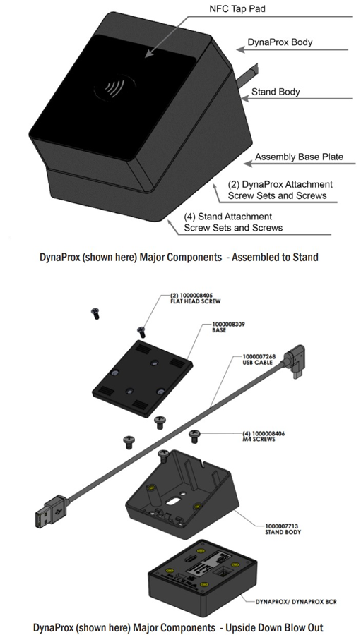
Major Components, see Figure 4-12 - DynaProx Major Components.
<figure><img src="https://2899238900-files.gitbook.io/~/files/v0/b/gitbook-x-prod.appspot.com/o/spaces%2F8D8HmfmyvOUbCM5xaHF8%2Fuploads%2FwPfpjSZVmjECujul9wX7%2Fimage.png?alt=media&amp;token=9cc4b0dc-a0ab-4ab3-82de-2cbdb2b23877" alt=""><figcaption></figcaption></figure>

<p align="center"><strong>Figure 4-12 - DynaProx Major Components</strong></p>

**Stand Contents:**

* Stand Body: The body of the stand. Angled for better ergonomics.
* Cable Channel: Allows the cable to be channeled out the back of the stand body.
* (4) M4 Screws: Attaches the stand body to the DynaProx device
* (2) Flat-head Screws: Attaches the base plate to the stand body. Base Plate: Bottom of stand, can attach the stand to counter tops Installation of DynaProx Stand

1. Place the DynaProx face down on a clean, soft surface to avoid scratching the front face of the device. Using minimal toque, use (4) M4 screws to attach the stand to the body

<figure><img src="https://2899238900-files.gitbook.io/~/files/v0/b/gitbook-x-prod.appspot.com/o/spaces%2F8D8HmfmyvOUbCM5xaHF8%2Fuploads%2FD2DwfzoanMWmIGSt7Npx%2Fimage.png?alt=media&amp;token=b0a2c025-4db6-4d61-9ed3-0d8f4e0fb3ee" alt=""><figcaption></figcaption></figure>

<p align="center"><strong>Figure 4-13 - Suggested Installation for DynaProx Stand</strong></p>

2. Insert the cable and connect securely to the DynaProx device. Clip the cable securely into the cable management hooks. Channel the cable outside the back end of the stand body.

<figure><img src="https://2899238900-files.gitbook.io/~/files/v0/b/gitbook-x-prod.appspot.com/o/spaces%2F8D8HmfmyvOUbCM5xaHF8%2Fuploads%2F0qy3BxXqU16osNyofzPz%2Fimage.png?alt=media&amp;token=025920c7-c57b-4908-998b-75b7641734cf" alt=""><figcaption></figcaption></figure>

<p align="center"><strong>Figure 4-14 - Cable Management</strong></p>

3. Align the assembly base plate and using the (2) flat-head screws, screw the base plate to the stand body. See Figure 4-15 – Baseplate Installation.

<figure><img src="https://2899238900-files.gitbook.io/~/files/v0/b/gitbook-x-prod.appspot.com/o/spaces%2F8D8HmfmyvOUbCM5xaHF8%2Fuploads%2FaWaZvvRkIS2aUcd2ZzSk%2Fimage.png?alt=media&amp;token=73848a6e-3d02-4118-9243-ab0144375ca6" alt=""><figcaption></figcaption></figure>

<p align="center"><strong>Figure 4-15 – Baseplate Installation</strong></p>

4. Assembly is complete. Additionally, you can secure the base plate to almost any surface using (2) additional screws, not included.

**Securing DynaProx Stand to Surface**

Follow Steps 1 through 2, then:

* Place baseplate on the location where you want to secure the device. Trace the baseplate and mark the two screw set locations (Drawn Outline). Remove the baseplate and drill down through the surface, checking to make certain everything is clear beneath.
* Attach the baseplate to the stand body following step 3. Then align the surface to the tracing.
* Using (2) M4 x 0.7mm thread pitch (not included) screws, screw up through the pre-drilled holes to the baseplate. Screws should be long enough to go through the surface and no more than 0.25” into the stand body.

<figure><img src="https://2899238900-files.gitbook.io/~/files/v0/b/gitbook-x-prod.appspot.com/o/spaces%2F8D8HmfmyvOUbCM5xaHF8%2Fuploads%2FiQhyzV4Gttttf9U18TLp%2Ffigure%20416.png?alt=media&amp;token=fdf56d4a-44e7-435e-8859-7fb8d1d9015d" alt=""><figcaption></figcaption></figure>

<p align="center"><strong>Figure 4-16 - Recommended Disassembly Procedure</strong></p>

#### **Disassembly**

Repeat assembly in reverse order to remove device from counter installation and stand. See Figure 4-16 - Recommended Disassembly Procedure.


---

# Agent Instructions
This documentation is published with GitBook. GitBook is the documentation platform designed so that both humans and AI agents can read, navigate, and reason over technical content effectively. Learn more at gitbook.com.

## Querying This Documentation
If you need additional information that is not directly available in this page, you can query the documentation dynamically by asking a question.

Perform an HTTP GET request on the current page URL with the `ask` query parameter, and the optional `goal` query parameter:

```
GET https://developer.magtek.com/downloads-compliance-and-marketing-materials/device-manuals-product-specific/dynaprox-manuals/installation-and-operation-manual/installation.md?ask=<question>&goal=<endgoal>
```

`ask` is the immediate question: it should be specific, self-contained, and written in natural language.
`goal` is optional and describes the broader end goal you are ultimately trying to accomplish on behalf of the user. GitBook uses it to tailor the answer towards what is most useful for that goal.

The response will contain a direct answer to the question and relevant excerpts and sources from the documentation.

Use this mechanism when the answer is not explicitly present in the current page, you need clarification or additional context, or you want to retrieve related documentation sections.
