This section of the DynaFamily Programmer's Manual lists available commands to initiate various ransactions in the device.
Applies to: All Dyna Family products
Information in this group
Section
Information
The host uses this command to start a payment transaction.
About
Pass-Through Mode is independent and separate from EMVCo Payment functions. This mode provides no access to any EMV payment kernels, and is out of scope from EMVCo certifications.
This mode is typically used by developers that require the need for non-payment low-level APDU communications with NFC cards, tokens, and devices.
The commands in this section provide the basic capability to communicate directly with the non-payment Contactless Card. They provide control of the polling process, and exchange of application protocol data units (APDU).
Typical Use Case examples of overall sequence:
ENTER Pass-Through Mode.
0xD112 - Set Property (Secured)
The host uses this command to set device configuration / settings securely. Properties that require security should specify that they do in their documentation. This command can also be used for properties that do not require security.
The details, request data and response data of this command are identical to what is documented in Set Property (Unsecured) - Command 0xD111, however, the command must be structured and sent according to what is documented in sequence of events 1-5 of Start Send File to Device (Secured) - Command 0xD811 .
Turn ON Polling
Set/Use LEDs / Buzzer
“Tap” card/device on reader.
Engage APDU transmit/ receive activities
Set/Use LEDs/ Buzzer
When transaction is completed:
Turn OFF Polling
EXIT Pass-Through Mode.
Pass-Through Mode Start/Stop - Command 0x3001
The host uses this command to enter or exit Pass-Through Mode.
The Host must “Enter Pass-Through Mode” prior to using any other commands in this section. Otherwise, subsequent commands will be “ignored” / “rejected”. When finished, the Host should “Exit Pass-Through Mode”. Once exited, the reader returns to its “normal state” and will accept traditional commands.
The host uses this command to provide the device with additional/modified data to resume a transaction that is currently paused.
Properties are stored in flash memory, which inherently has a limited number of read- write cycles before it begins to wear. For this reason, MagTek recommends setting properties as few times as possible over the lifecycle of the device.
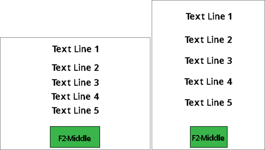
UI Page Option 0x00 Layout
The host uses this option to display a maximum of 5 lines of host-provided text, and 1 optional green functional button, Middle – label with a String ID that associates it with a configured String message. See Table – Default User Interface String IDs and Strings.
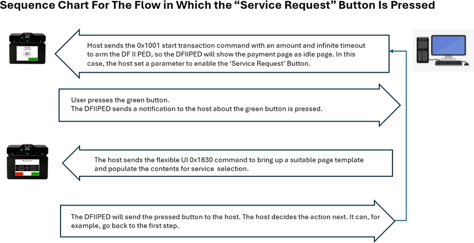
When the user presses this button, the device sends a notification to the host to indicate this button is pressed. See User Interface Host Action Request - Notification 0x1803. After that, the host will decide what to do next.
Recommend maximum number of characters setting for this page:
Landscape Screen Orientation
Each text line can fit about:
18 Upper case wide size characters (example: “WM”)
23 Upper case regular size characters (example: “ABC”)
21 lower case wide size characters (example: “wm”)
30 lower case regular size characters (example: “abc”)
Button text can fit about:
5 Upper case wide size characters (example: “WM”)
8 Upper case regular size characters (example: “ABC”)
Each text line can fit about:
13 Upper case wide size characters (example: “WM”)
17 Upper case regular size characters (example: “ABC”)
0x20nn - Banking Functions (Touch/Display Only)
Banking Functions
This section of the DynaFamily Programmer's Manual lists banking functions commands.
Applies to: All Dyna Family products
Information in this group
Section
Information
This command directs the device to prompt the cardholder to enter a PIN when a card is not present or is not presented.
0xD1nn - Settings and Information
Settings and Information
This section of the DynaFamily Programmer's Manual lists settings and information commands.
Applies to: All Dyna Family products
Information in this group
Section
Information
The host uses this command to get information about the device or its configuration / settings.
0x11nn - NFC/MIFARE Pass Through Commands (Contactless Only)
NFC/MIFARE Pass Through Commands (Contactless Only)
After an NTag/MIFARE Ultralight is activated, the host uses this command to send commands and receive responses to and from a NTag/MIFARE Ultralight.
Applies to: All Dyna Family products
Information in this group
Section
Information
After an NTag/MIFARE Ultralight is activated, the host uses this command to send commands and receive responses to and from a NTag/MIFARE Ultralight.
0xDFnn - Diagnostics and Utilities
Diagnostics and Utilities
This section of the DynaFamily Programmer's Manual lists diagnostic and utility commands.
Applies to: All Dyna Family products
Information in this group
Section
Information
The host uses this command to prompt the device for a response that contains the same payload it sent.
Need More Help
Need Help?
For additional support, please contact MagTek Support:
Technical Support:
📧 Email:
0x1830 - Display Flexible UI Pages (Display Only)
This command allows the host to bring up standalone pages. A page is considered standalone if it’s stateless, meaning it will be:
Shown on the display.
Can allow user input.
Returns user input result to the host.
UI Page Option 0x01 and 0x02 Layout
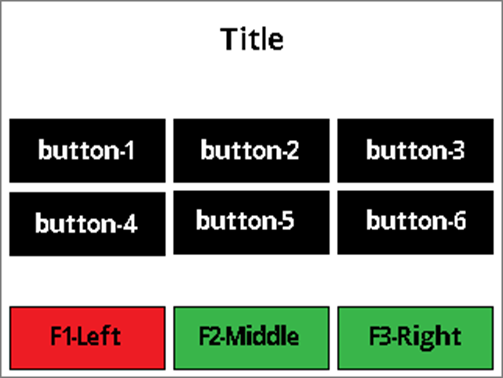
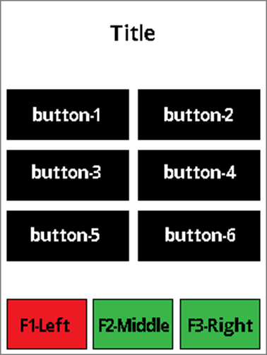
The host uses UI Page Option 0x01 to display a page with a title, a maximum of 6 data buttons (2 rows and 3 columns in Landscape Screen Orientation, 3 rows and 2 columns in Portrait Screen Orientation) with text, and maximum 3 functional buttons with a color option of red, green, or yellow.
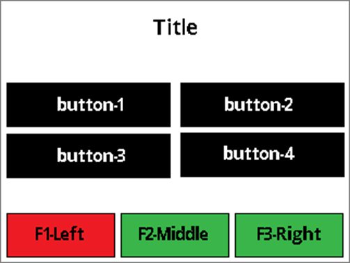
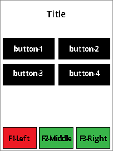
The host uses UI Page Option 0x01 to display a page with a title, maximum of 4 data buttons (2 rows and 2 columns in Landscape Screen Orientation, 2 rows and 2 columns in Portrait Screen Orientation) with text, and maximum 3 functional buttons with a color option of red, green, or yellow.
The host uses UI Page Option 0x02 to display a page with a title, maximum of 6 data buttons (2 rows and 3 columns in Landscape Screen Orientation, 3 rows and 2 columns in Portrait Screen Orientation) with $Amount, and maximum 3 functional buttons with a color option of red, green, or yellow.
The host uses UI Page Option 0x02 to display a page with a title, maximum of 4 data buttons (2 rows and 2 columns in Landscape Screen Orientation, 2 rows and 2 columns in Portrait Screen Orientation) with $Amount, and maximum 3 functional buttons with a color option of red, green, or yellow.
0x1Fnn - Device Control
This section of the DynaFamily Programmer's Manual lists available Device Control commands to initiate various functions in the device.
0x1840 - Card Emulation
Card emulation is initiated by receiving a 0x1840 command from the host. The device will prepare card emulation with the parameters provided in the command and start card emulation.
The sequence of events is as follows:
1
The host ensures the device is not currently running another command, for example, that it is not running a transaction or PIN entry.
2
0x30nn - Generic Pass-Through Commands
Pass-Through Mode is independent and separate from EMVCo Payment functions. This mode is typically used by developers that require the need for non-payment low-level APDU communications with NFC cards, tokens, and devices.
0xD9nn - Process Files
This section of the DynaFamily Programmer's Manual lists commands to process firmware file.
A diagram of a device Description automatically generated
A screenshot of a diagram Description automatically generated
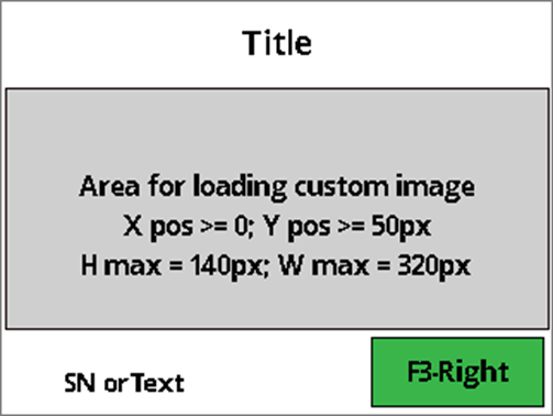
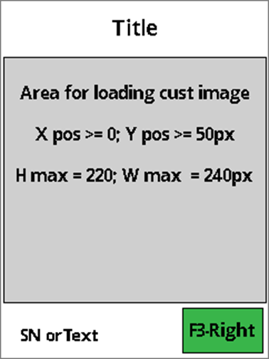
The host sends the 0x1830 command with UI Page Option set to 0x06 (Flexible UI Gen. 2 page), which displays a bitmap. The device sends User Event Notifications for each tap on the touchscreen (requires signed image).
The host uses this command to display Flexible UI pages in the following layout:
Request Data for Command 0x1831
Request Example – (Display Enter Sale Amount Page)
Response Example
Sequence for Flexible UI Gen. 2 mode
The button with **$**Amount value is host provided. The title, data buttons text, and functional buttons are labeled with String IDs associated with configured String messages. See Table – Default User Interface String IDs and Strings. When the user presses any button, the device sends a notification to the host to indicate the corresponding button is pressed. See User Interface Host Action Request - Notification 0x1803. After that, the host will decide what to do next.
Landscape Screen Orientation:
Title text:
~18 Upper case wide size characters (example: “WM”)
~23 Upper case regular size characters (example: “ABC”)
~21 lower case wide size characters (example: “wm”)
~30 lower case regular size characters (example: “abc”)
3-columns data button text:
~5 Upper case wide size characters (example: “WM”)
~8 Upper case regular size characters (example: “ABC”)
2-columns data button text:
~9 Upper case wide size characters (example: “WM”)
~13 Upper case regular size characters (example: “ABC”)
Functional button text:
~5 Upper case wide size characters (example: “WM”)
~8 Upper case regular size characters (example: “ABC”)
Portrait Screen Orientation:
Title text:
~13 Upper case wide size characters (example: “WM”)
Recommended maximum number of characters for this page
The Layout for a page with a title, a maximum of 4 data buttons with text/$Amount, and a maximum of 3 functional buttons:
The host can use this command to extend a session for open protocol interfaces, such as the WLAN interface, which require session management to meet PCI requirements.
The host can use this command to terminate a Bluetooth LE connection.
The host can use this command to erase all Bluetooth® LE bonds.
The host uses this command to specify which notifications the device should send on each of its available interfaces.
Need More Help
Need Help?
For additional support, please contact MagTek Support:
Technical Support:
📧 Email:
The host composes a command request in the format described below and sends it to the device.
3
Device validates and prepares
The device receives the command and verifies that the parameters are valid and the device is in a state that allows the execution of card emulation.
4
Device prompts customer (if display available)
If the device has a display, a prompt will be displayed asking the customer to tap their phone to the device.
5
Timeout behavior and response
If the timeout parameter is not included or set to 0x00, then there is no timeout.
If the timeout parameter is set to a specific number of seconds, the device returns a command response message with its Operation Status Summary byte set to 0x01 (OK, Started / Running).
6
Host can cancel emulation
The host may issue a 0x1840 command with Tag 0x81 set to 0x00 to cancel the execution of card emulation.
7
Completion notification
After the timeout expires, host cancel or the card is read, the device sends a 0x1805 notification to inform the host.
Tag
Len
Value / Description
Req
Default
/81
01
Start/Cancel
0x00 = Cancel (See the example of 0x1840 cancel command below)
After entering the Pass-Through Mode, the host use this command to request the device to start polling for a Type A and Type B PICC until it detects a PICC or times out.
After the NFC Type A or Type B card is activated, the host uses this command to send application-level APDUs to a PICC that supports ISO 14443-4 Protocol.
The host uses this command to set device configuration / settings securely. Properties that require security should specify that they do in their documentation.
Need More Help
Need Help?
For additional support, please contact MagTek Support:
After a MIFARE DESFire Light/EV1/EV2/EV3 Tag is activated, the host uses this command to send commands and receive responses to and from a MIFARE DESFire Tag.
The host uses this command to commit a file previously uploaded using Command 0xD801 into the device’s permanent memory after the device has authenticated the file.
Process Files
Applies to: All Dyna Family products
Information in this group
Need More Help
Need Help?
For additional support, please contact MagTek Support:
This section of the DynaFamily Programmer's Manual lists commands to move, save, and manipulate files.
Applies to: All Dyna Family products
Information in this group
Section
Information
Large blobs of data uploaded to / downloaded from the device are referred to as “files” and share a common set of commands documented here, and special message type Data File Message.
0xEnnn - Security
Security
This section of the DynaFamily Programmer's Manual lists available security commands to utilize various functions in the device.
Applies to: All Dyna Family products
Information in this group
Section
Information
The host uses this command to request challenge data from the device, which the host can then use to perform a specific sensitive operation / modify a specific type of device setting.
0xEF06 - Change Device Lock State
The host can use this command to change the device’s lock state. To get the device’s lock state or to set it using MagTek security see Device Lock State - Property 1.2.5.2.1.1. The value of the device lock state will revert to the value of Device Lock State After Reset - Property 1.2.5.2.1.2 after a reset or a power cycle. See Device Lock Feature for more information.
Change Device Lock State - Request Data for Command 0xEF06
Tag
Len
Value / Description
Typ
Req
Default
Tag
Len
Value / Description
Typ
Req
Default
0x18nn - User Interface
The host uses these commands to interact with various areas of the device's user interface.
0x1802 - Report Cardholder Selection
The host uses this command to provide a cardholder selection to the device when the device itself does not have a display or inputs to prompt the cardholder for a selection.
Sequence of events:
1
The host has already invoked Start Transaction - Command 0x1001 and the transaction is still in process.
2
0x1806 - Personal Info Entry
The host uses this command to prompt a cardholder for customer information.
1
The host ensures the device is not currently running another command (for example, it is not running a transaction using .
2
If the host determines it should request customer information, it composes a command request in the format described below.
0x1F01 - Reset Device
The host uses this command to reset the device.
1
The host constructs the command request for Command 0x1F01 - Reset Device in the format below.
2
The host sends the command request to the device.
3
0x1F03 - Extend Session (Session Management Only)
The host can use this command to extend a session for open protocol interfaces, such as the WLAN interface, which require session management to meet PCI requirements.
The sequence of events is as follows:
1
The host establishes a session with the device on a given interface. For the WLAN interface, a session starts when the host establishes a TLS websocket connection with the device.
2
0x1F04 - Terminate Bluetooth LE Connection (Bluetooth LE Only)
The host can use this command to terminate a Bluetooth® LE connection. The host may also be able to terminate a Bluetooth® LE connection directly without using this command.
The sequence of events is as follows:
1
The host constructs the command request for Device in the format below.
2
0x1F05 - Erase All Bluetooth LE Bonds (Bluetooth LE Only)
The host can use this command to erase all Bluetooth® LE bonds. The user should then forget the device and re-pair the device on any host that it was previously paired with if that host needs to communicate with the device again.
The sequence of events is as follows:
1
The host constructs the command request for Command 0x1F01 - Reset Device in the format below.
2
0x3001 - Pass-Through Mode Start/Stop
The host uses this command to enter or exit Pass-Through Mode.
The Host must “Enter Pass-Through Mode” prior to using any other commands in this section. Otherwise, subsequent commands will be “ignored” / “rejected”. When finished, the Host should “Exit Pass-Through Mode”. Once exited, the reader returns to its “normal state” and will accept traditional commands.
0x1008 - Cancel Transaction
The host can use this command to cancel a transaction in progress that it initiated using Start Transaction - Command 0x1001.
Sequence of events:
1
The host has already called Start Transaction - Command 0x1001 and the transaction is still in process.
2
0x1004 - Resume Transaction
The host uses this command to provide the device with additional/modified data to resume a transaction that is currently paused.
Tag
Len
Value / Description
Typ
Req
Default
0xEF02 - Generate CSR Keys (WLAN Only)
The host uses this command to generate a key pair to be used for a certificate signing request (CSR). The key pair generated will be 256 bit elliptic-curve (EC) keys. The key pair generated will be saved to non-volatile memory in the device and will overwrite any existing CSR key pair. The key pair will persist in non-volatile memory associated with a CSR until it is either overwritten or until a leaf certificate is loaded into the device with Start Send File to Device (Secured) - Command 0xD811 that contains a public key that matches the key pair at which point the key pair will be associated with that certificate instead of a CSR.
The sequence of events is as follows:
1
The host constructs the command request in the format below and sends it to the device.
2
0xEF07 - Change Device Lock Passcode
The host can use this command to change the device’s lock passcode. The value of the device lock passcode is stored in non-volatile memory so changes made to it will persist after the device is reset or power cycled. To change the device lock passcode using MagTek security or to see its default value see Device Lock Passcode - Property 1.2.5.2.1.3. See Device Lock Feature for more information.
Tag
Len
Value / Description
Typ
Req
Default
0xDF01 - Echo
The host uses this command to prompt the device for a response that contains the same payload it sent.
1
The host constructs the command request for Echo - Command 0xDF01 in the format below, populating any of the available parameters with any data. The total length of data to be echoed across all parameters must not exceed 128 bytes.
/82
01
Timeout in seconds
0x00 = No timeout
0x01 to 0xFF = 1 to 255 seconds
O
0x00
/83
<= 254
URL
URL to use as card data. Required when starting card emulation. Optional and ignored if canceling emulation. Example: https://www.magtek.com/
Passcode — The value of the passcode depends on the value of the passcode format parameter.
If the passcode format is set to Clear (0x00), then the value of the passcode is the passcode in the clear and can have a length of 4–63 bytes.
If the passcode format is set to Fixed SHA-256 (0x01), then the value of the passcode is the 32-byte SHA-256 hash value of the passcode
If the passcode format is set to Variable SHA-256 (0x02), then the value of the passcode is the 32-byte SHA-256 hash value of: an 8-byte random challenge token followed by the 4–63 byte passcode. The challenge token must have been retrieved from the device within the last 5 minutes using Command 0xE001 - Get Challenge
B
M
-
-
End of any wrappers, at minimum including Request Message
EF06 = Change Device Lock State -Command 0xEF06
-
-
-
No parameters.
-
-
End of any wrappers, at minimum including Response Message
Beginning of any wrappers, at minimum including Request Message
-
-
EF06 = Change Device Lock State - Command 0xEF06
-
Beginning of any wrappers, at minimum including Response Message
-
Response Data for Change Device Lock State - Command 0xEF06
The host uses this command to request that the device display a message for the cardholder.
The host uses this command to direct the device to arm or disarm the barcode reader for reading a barcode outside the scope of a transaction.
The host uses this command to start a buzzer for playing a sequence of tones.
The host uses this command to prompt a cardholder for customer information.
The host uses this command to control the 4 LEDs of the device when the device is not in non-User Control LED states.
The host uses this command to trigger the device to immediately show a pre-loaded image on the display, provided the device is not in a mode that has exclusive use of the display (such as during a transaction).
The host uses this command to direct the device to immediately show a QR code on the display, provided the device is not in a mode that has exclusive use of the display (such as during a transaction).
The host uses this command to trigger the device to immediately show a bitmap file the host includes as a parameter, provided the device is not in a mode that has exclusive use of the display (such as during a transaction).
This command allows the host to bring up standalone pages.
Card emulation is initiated by receiving a 0x1840 command from the host.
The host uses this command to provide a cardholder selection to the device when the device itself does not have a display or inputs to prompt the cardholder for a selection.
Need More Help
Need Help?
For additional support, please contact MagTek Support:
Technical Support:
📧 Email:
During the transaction, if the device does not have a display or touchscreen but needs to show information to the cardholder or needs the cardholder to make a selection, it sends the host User Interface Host Action Request - Notification 0x1803 to report Display / Cardholder Selection and supporting information.
3
Host prompts cardholder
The host uses its user interface to request a selection from the cardholder based on the information and selectable items provided by the notification message.
4
Host reports the selection to the device
The host sends the user selection to the device by sending Command 0x1802 in the format described below.
Beginning of any wrappers, at minimum including Request Message.
Tag
Len
Value / Description
Typ
Req
Default
1802
Report Cardholder Selection = Command 0x1802
If the request started successfully, the Request Status in the message wrapper is OK, Started / Running, All good / requested operation was successful.
Response Data for Report Cardholder Selection - Command 0x1802
Beginning of any wrappers, at minimum including Response Message.
Request Data for Report Cardholder Selection - Command 0x1802
Request Example (Hex)
Response Example (Hex)
3
Present keypad
The device presents a keypad interface to the cardholder on the display.
4
Device notifies host
The device sends 7.5.3 Notification 0x1805 - User Interface Operation Complete to the host to report data available, or hardware failure.
5
Host retrieves data
If the device reported data available, the host can retrieve the data as defined in Table 350 – Notification Detail Codes and Table 352 – Notification Payload for Personal Info Entry.
Tag
Len
Value / Description
Typ
Req
Default
Beginning of any wrappers, at minimum including Request Message
Tag
Len
Value / Description
Typ
Req
Default
Beginning of any wrappers, at minimum including Response Message
If the request started successfully, the Request Status in the message wrapper is: OK, Started / Running, All good / requested operation was successful.
Request Data for Command 0x1806 – Personal Info Entry
Response Data for Personal Info Entry
Request Example
Response Example
Device responds
The device sends a response in the format below to the host.
4
Device resets
The device starts an automatic reset within 500ms.
Tag
Len
Value / Description
Typ
Req
Default
Beginning of any wrappers, at minimum including Request Message
Tag
Len
Value / Description
Typ
Req
Default
Beginning of any wrappers, at minimum including Response Message
Construct the command request
Send the command request
Example (Hex)
AA 00 81 04 01 12 1F 01 84 02 1F 01
Response Example (Hex)
AA 00 81 04 82 12 1F 01 82 04 00 00 00 00
Reset Device - Request Data for Command 0x1F01
Reset Device - Response Data for Command 0x1F01
Request Example - Command 0x1F01
Response Example - Command 0x1F01
The device starts a countdown timer for a 30 minute session timeout period.
3
Session expiring notifications
Five minutes before the session timeout period expires, the device starts repeatedly (every minute) sending Device Information Update - Notification 0x1001 to report Session Management / Session Expiring Soon.
4
Host may extend the session
The host may extend the session multiple times, until the device automatically resets to meet PCI’s 24 hour self-test requirement, by sending any command request using the same interface before the timeout occurs. Upon receiving the command, the device resets the session countdown timer to 30 minutes. This helps prevent the session from expiring while the host is actively using the device, including when the device is performing a transaction.
If the host wants to extend the session but does not need to send another command, it may follow these steps at any time during the session:
1
Construct command request
The host constructs the command request in the format below.
2
The host sends the command request to the device.
3
The device sends a response in the format below to the host.
4
The device resets the session countdown timer to 30 minutes.
5
Session expiration
When the session expires, the device closes the websocket connection.
For the WLAN interface, if the device is configured to allow connections to more than one client at the same time with Maximum Client Connections - Property 1.2.2.1.1.A and more than one client is connected, then the following applies. There is always only a single session and it applies to all clients. There is not a separate session for each client. The session starts when the first client connects. Only one client needs to send a command on its connection to extend the session. The other clients do not need to send any commands. When the session expires, all clients will be disconnected.
Tag
Len
Value / Description
Typ
Req
Default
Beginning of any wrappers, at minimum including Request Message
Tag
Len
Value / Description
Typ
Req
Default
Beginning of any wrappers, at minimum including Response Message
Session start
Device session timer
Request (Hex)
AA00 810401551F03 8402 1F03
Response (Hex)
AA00 810482551F03 820400000000 8402 1F03
Extend Session (Session Management Only) - Request Data for Command 0x1F03
Extend Session (Session Management Only) - Response Data for Command 0x1F03
Request Example - Command 0x1F03
Response Example - Command 0x1F03
The host sends the command request to the device.
3
The device sends a response in the format below to the host.
4
The device terminates the Bluetooth® LE connection within around 500 ms.
Tag
Len
Value / Description
Typ
Req
Default
Beginning of any wrappers, at minimum including Request Message
Tag
Len
Value / Description
Typ
Req
Default
Beginning of any wrappers, at minimum including Response Message
This parameter defines how long the device to stay in the Pass-Through Mode
· 0x00 = No timeout
· 0x01 to 0xFF = 1 to 255 seconds
R
82
01
Pass-Through Mode
· 0x00 = Stop Pass-Through Mode. This mode can only be used after the device in the Pass-Through Mode. The device automatically turn off the RF Antenna after exit the Pass-Through Mode. Device returns error if it is not in the Pass-Through Mode.
· 0x01 = Start Pass-Through Mode. This mode can only be used when the device is in Idle state.
B
R
End of any wrappers, at minimum including Request Message
Tag
Len
Value / Description
Typ
Req
Default
Beginning of any wrappers, at minimum including Response Message
Request Data for Pass-Through Mode Start/Stop - Command 0x3001
Req
Response Data for Pass-Through Mode Start/Stop - Command 0x3001
Request Example - Command 0x3001
Response Example - Command 0x3001
The host constructs the command request in the format below.
3
Send the command request
The host sends the command request to the device.
4
Device sends a response
The device sends a response in the format below to the host:
If the transaction is in a state where it cannot be canceled, the device’s response returns operation status detail: Failed, Device State Issue, Cannot Cancel.
If there is no transaction in progress, the device’s response returns operation status detail: Failed, Device State Issue, No Transaction.
If the device successfully cancels the transaction, the device’s response returns operation status detail: All Good, Requested Operation Was Successful, shows "CANCELED" and returns to the idle state. The display (if any) shows "CANCELED".
Tag
Len
Value / Description
Typ
Req
Default
Beginning of any wrappers, at minimum including Request Message
Tag
Len
Value / Description
Typ
Req
Default
Beginning of any wrappers, at minimum including
Example (Hex)
Example (Hex)
Host has already started a transaction
Construct the command request
AA 00 81 04 01 13 10 08 84 02 10 08
AA 00 81 04 82 13 10 08 82 04 00 00 00 00
Request Data for Cancel Transaction - Command 0x1008
Response Data for Cancel Transaction - Command 0x1008
Request Example
Response Example
1004 = Resume Transaction - Command 0x1004
81
01
Resume Code. Indicates the pause state the transaction will resume from:
0x00 = Waiting for ARPC
B
R
83
var
Reserved
B
O
84
var
ARPC Data. This contains an EMV ARPC Type.
B
R
86
var
Transaction TLV Update. Not applicable when Resume Code = Waiting for ARPC
B
O
End of any wrappers, at minimum including Request Message
Tag
Len
Value / Description
Typ
Req
Default
Beginning of any wrappers, at minimum including Response Message
Resume Transaction - Request Data for Command 0x1004 -
Beginning of any wrappers, at minimum including Request Message
Response Data for Command 0x1004 - Resume Transaction
If the request started successfully, the Request Status in the message wrapper is: OK, Started / Running, All good / requested operation was successful.
Request Example
Response Example
Device sends immediate response
The device sends a response in the format below to the host to indicate that key pair generation has been started.
3
Device sends notification when generation completes
Once the device finishes generating the key pair, it will send Device Information Update - Notification 0x1001 with the category set to key management and the reason set to CSR keys generated to indicate that the key pair generation process has completed.
The device typically takes around a second or two to generate a 256 bit EC key pair. If this command is extended in the future to support 2048 bit RSA keys, then it will take an average of 30 seconds and sometimes much longer to generate the RSA keys. That is why a notification is used to indicate that the key pair has been generated instead of a command response that indicates that it is complete.
4
Host typically requests CSR next
The host will typically send Generate CSR (WLAN Only) - Command 0xEF03 as the next step. See that command for more detail and more potential steps.
Tag
Len
Value / Description
Typ
Req
Default
Beginning of any wrappers, at minimum including Request Message
Tag
Len
Value / Description
Typ
Req
Default
Beginning of any wrappers, at minimum including Response Message
Example (Hex):
Host sends command request
Example (hex)
AA00 81 04 0155EF02 84 02 EF02
AA00 81 04 8205EF02 82 04 01000000 84 02 EF02
Generate CSR keys (WLAN Only) - Request Data for Command 0xEF02
Response Data for Generate CSR keys (WLAN Only) - Command 0xEF02
Request Example - Command 0xEF02
Response Example - Command 0xEF02
Beginning of any wrappers, at minimum including Request Message
0x00 – Infinite. Device leaves the requested page on the display until the host initiates a change.
B
R
82
01
UI page option
0x00 – Enter Sale Amount page. Device responds with User Interface Host Action Request with ‘Touchscreen, $Amount button selected’ content - Notification 0x1803.
B
R
The host uses this command to send a firmware image file, signed by MagTek, to the device as the first step in updating firmware.
The host uses this command to start sending secured files to the device for storage or processing. It is similar to Start Send File to Device (Unsecured), but is used to send a different subset of file types that impact device security and require some form of authentication from the host.
The host uses this command to start sending unsecured files to the device for storage or processing. It is similar to Start Send File to Device (Secured) but is used to send a different subset of file types that do not impact device security.
The host uses this command to request a file stored on the device. File types include standard files (images and certificates), MagTek custom files (configuration, firmware), and in some cases even large data blob output (such as signature capture data).
The host uses this command to request the file information of a file stored on the device. File types include standard files (images and certificates), MagTek custom files (configuration, firmware), and in some cases even large data blob output (such as signature capture data).
The host uses this command to request that the device display a message for the cardholder.
The sequence of events is as follows:
1
The host ensures the device is not currently running another command, for example, that it is not running a transaction using Start Transaction - Command 0x1001.
2
The host selects the message it wants to display from the list of available pre-determined strings.
3
The host composes a command request in the format below, and sends it to the device.
4
The device displays the requested message.
If the Timeout parameter is set to Infinite, the device returns a command response message with Response Status, Operation Status Summary byte set to 0x00 (OK, Done) after which the host is free to send further commands.
If the Timeout parameter is not set to Infinite:
Tag
Len
Value / Description
Typ
Req
Default
Tag
Len
Value / Description
Typ
Req
Default
Example (Hex):
0x1804 - Read Barcode (BCR Only)
The host uses this command to direct the device to arm or disarm the barcode reader for reading a barcode outside the scope of a transaction. This is an immediate directive. To read barcodes within the scope of a transaction, use Start Transaction - Command 0x1001 and its barcode reader parameters instead.
The sequence of events is as follows:
1
The host ensures the device is not currently running another command, for example, that it is not running a transaction using Start Transaction - Command 0x1001.
2
The host composes a command request in the format below and sends it to the device.
3
If the device has a display, it shows a prompt SCAN BARCODE.
4
The device enables the barcode reader.
The device returns a command response message with Response Status, Operation Status Summary byte set to 0x00 (OK, Done) after which the host is free to send further commands.
The host may end the barcode reading session by calling this command again with the Enable parameter set to Disable.
Tag
Len
Value / Description
Typ
Req
Default
Tag
Len
Value / Description
Typ
Req
Default
0x1805 - Buzzer
The host uses this command to start a buzzer for playing a sequence of tones. Each sequence can have a minimum of 1 to maximum of 10 tones.
1
The sequence of events is as follows:
The host ensures the device is not currently running another command, for example, that it is not running a transaction using Start Transaction - Command 0x1001.
2
The host composes a command request in the format below and sends it to the device.
3
The device plays a specific tone sequence as the command specified. After finish, the device sends User Interface Operation Complete - Notification 0x1805 to report Buzzer/Buzzer Result.
The host should wait for User Interface Operation Complete - Notification 0x1805 - before sending another command.
Tag
Len
Value / Description
Typ
Req
Default
Tag
Len
Value / Description
Typ
Req
Default
0x1821 - Show Image (Display Only)
The host uses this command to trigger the device to immediately show a pre-loaded image on the display, provided the device is not in a mode that has exclusive use of the display (such as during a transaction). This is an immediate and temporary directive. For a solution that affects the device’s idle page behavior on a more permanent basis, see Property 1.2.3.1.1.1 Custom Idle Page Image. This command is different from Show Bitmap Image - Command 0x1823 in that the bitmaps are pre-loaded and persistently stored in the device and can not be composited with each other.
The sequence of events is as follows:
1
Prepare the image slot
The host makes sure it has loaded the image into at least one of the device’s Custom Idle Page Image slots using Start Send File to Device (Unsecured) - Command 0xD812.
2
The host makes sure the device is in Active/Idle state (meaning the display is fully powered on and is not in a mode that has exclusive use of the display, such as processing a transaction).
3
The host calls this command to show the image loaded into the desired slot number.
4
The device shows the specified image on the display until the device is no longer in Active/Idle.
Tag
Len
Value / Description
Typ
Req
Default
Tag
Len
Value / Description
Typ
Req
Default
If the request started successfully, the Request Status in the message wrapper is All Good, Requested Operation Was Successful.
0x3002 - Start/Stop Polling
After entering the Pass-Through Mode, the host use this command to request the device to start polling for a Type A and Type B PICC until it detects a PICC or times out. This command automatically turns on the RF Antenna.
After NFC Type A card is detected, the device will stop the polling, activate the card and
Send a notification that identifies the ISO 14443 Type A (Supports ISO 14443-4 protocol). See Notification 0x0301 – Pass-Through Mode Information Update.
Send another notification with the UID as a payload.
After NFC Type B card is detected, the device will stop the polling, activate the card and
Send a notification that identifies the ISO 14443 Type B (Supports ISO 144443-4 Protocol). See Pass-Through Mode Information Update - Notification 0x0301
Send another notification with the UID as a payload.
If the card is not supported, the device will send error notification and stop the polling.
0x3003 - ISO 14443-4 APDU Pass-Through Commands
After the NFC Type A or Type B card is activated, the host uses this command to send application-level APDUs to a PICC that supports ISO 14443-4 Protocol. The device sends the PICC response back to the host.
Request Data for Command 0x3003 – ISO 14443-4 APDU Pass-Through Commands
Tag
Len
Value / Description
Typ
Req
Default
Example (Hex)
0xE001 - Get Challenge
The host uses this command to request challenge data from the device, which the host can then use to perform a specific sensitive operation / modify a specific type of device setting. Information about how the host should pass the required challenge data to the device is included in the documentation for all commands that use this security mechanism.
The sequence of events is as follows:
1
The host already wants to perform a secured operation that requires a challenge (for example Command 0xEEEE - Send Secured Command to Device).
2
The host constructs the command request for Get Challenge -Command 0xE001 in the format below.
3
The host sends the command request to the device.
4
The device generates a random number for the challenge, stores it locally, and sends a response in the format below to the host.
5
The device starts a 5 minute countdown timer during which the challenge is valid. If the host takes no action within 5 minutes, the timer expires, the device erases the challenge data, and the device must retrieve a fresh challenge to perform the operation it wants to perform. This binding of the command to a specific time period allows the device to detect and reject commands that have been captured/intercepted at one point in time and replayed later.
Tag
Len
Value / Description
Typ
Req
Default
Tag
Len
Value / Description
Typ
Req
Default
0xD901 - Commit Firmware from File
The host uses this command to commit a file previously uploaded using Command 0xD801 - Load (Firmware File) into the device’s permanent memory after the device has authenticated the file.
Sequence of events:
1
Compose and send request
The host composes a command request in the format below, and sends it to the device.
2
Device acknowledges request
The device sends a response in the format below.
3
The device writes the image file to permanent storage.
4
If the commit operation was successful, the device sends Firmware Update Successful - Notification 0x0905 to the host. If the commit operation was not successful, the device sends Firmware Update Failed - Notification 0x0906 to the host. In both cases, the device automatically resets.
Tag
Len
Value / Description
Typ
Req
Default
Tag
Len
Value / Description
Typ
Req
Default
If the request started successfully, the Request Status in the message wrapper is: OK, Started / Running, All good / requested operation was successful.
0xD831 - Delete File from Device
The host uses this command to request the deletion of a file stored on the device.
The sequence of events is as follows:
1
Host composes and sends request
The host composes a command request in the format below and sends it to the device.
2
Device processes request
The device reads and erases the file and sends a response to the host in the format below.
3
If the file read or the file erase fails, a response of failure will be sent to the host.
The host uses this command to prompt a cardholder for a signature.
The sequence of events is as follows:
1
The device completes a transaction after the host invokes Start Transaction - Command 0x1001. At the end of the transaction, the device has provided data to the host in Transaction Operation Complete - Notification 0x0105. The host may send Command 0x1801 to the device to get a signature file without doing a transaction. The signature file can be encrypted if enabled.
2
0x1807 - LED Control
The host uses this command to control the 4 LEDs of the device when the device is not in non-User Control LED states. If the host sets an LED timer, the device reports completion via Notification User Interface Operation Complete - 0x1805 after the LED operation finishes.
Non-User Control LED state is when the device is in tamper, or currently running transaction with these commands:
Start Transaction - Command 0x1001
Card Emulation - Command 0x1840
0x1F02 - Set Notification Subscriptions
The host uses this command to specify which notifications the device should send on each of its available interfaces. By default, the device sends notifications to the host on all interfaces.
1
The sequence of events is as follows:
The host constructs the command request in the format below.
Commands
The DynaFamily card readers accept the Multi-Interface Card Reader Platform (MMS) command set — the messages you send to run transactions, read cards, drive the display and prompts, manage keys and files, and query or configure the reader. Full syntax, parameters, responses, and examples are maintained in the shared reference.
81
01
Cardholder Selection Request Status
- 0x00 = Cardholder Selection Request completed, see Selection Result parameter.
- 0x01 = Cardholder Selection Request canceled by cardholder, Transaction Aborted.
- 0x02 = Cardholder Selection Request timed out, Transaction Aborted.
B
R
82
01
Selection Result — Menu item index the cardholder selected. If the cardholder made no selection or the operation terminated abnormally, the device does not include this parameter.
B
O
End of any wrappers, at minimum including Request Message.
No parameters.
End of any wrappers, at minimum including Response Message.
1806 = Command 0x1806 – Personal Info Entry
81
01
Capture Type
0x01 = Phone Number: Capture the phone number
0x02 = Social: Capture the social security number
0x03 = Zip code: Capture the zip code
0x04 = Employee ID: Capture Employee ID number
0x05 = Birth Date: Capture birth date in USA format
0xFF = Cancel Capture: Cancel any of the capture commands
B
R
82
01
Encryption for user data (Optional)
00 – No Encrypt
01 - Encrypt
B
R
Beginning of any wrappers, at minimum including Request Message
1806 = Command 0x1806 – Personal Info Entry
No parameters.
Beginning of any wrappers, at minimum including Response Message
1F01 = Reset Device - Command 0x1F01
81
01
Power Off Option
0x00 = Reset
0x01 = Power Off
Power off only works while a device is running on its battery. If a device is powered off while it is powered by USB, the device will immediately turn back on.
B
O
0x00
End of any wrappers, at minimum including Request Message
1F01 = Reset Device - Command 0x1F01
No parameters.
End of any wrappers, at minimum including Response Message
1F04 = Terminate Bluetooth® LE Connection - Command 0x1F04
No parameters.
End of any wrappers, at minimum including Request Message
1F04 = Terminate Bluetooth® LE Connection - Command 0x1F04
No parameters.
End of any wrappers, at minimum including Response Message
1F05 = Erase All Bluetooth® LE Bonds - Command 0x1F05
No parameters.
End of any wrappers, at minimum including Request Message
1F05 = Erase All Bluetooth LE Bonds - Command 0x1F05
No parameters.
End of any wrappers, at minimum including Response Message
No parameters.
End of any wrappers, at minimum including Response Message
1004 = Resume Transaction - Command 0x1004
No parameters.
End of any wrappers, at minimum including Response Message
Request Data for Command 0x3002 – Start/Stop Polling
Response Data for Command 0x3002 – Start/Stop Polling
Request Example - Command 0x3002
Response Example - Command 0x3002
The device returns a command response message with its Response Status, Operation Status Summary byte set to 0x01 (OK, Started / Running).
While the host is waiting for the timeout to expire, it should not send any commands to the device, because the device is busy processing the current command.
After the timeout period expires, the device blanks the display and sends User Interface Operation Complete - Notification 0x1805 to inform the host.
End of any wrappers, at minimum including Response Message
Beginning of any wrappers, at minimum including Request Message
Beginning of any wrappers, at minimum including Response Message
Request Data for Command 0x1803 - Display Message (Display Only)
Response Data for Display Message (Display Only) - Command 0x1803
Request Example
Response Example
The device returns a command response message with its Response Status, Operation Status Summary byte set to 0x01 (OK, Started / Running).
While the host is waiting for the timeout to expire, it should not send any commands to the device, because the device is busy processing the current command.
After the device reads a barcode or the timeout period expires, the device sends User Interface Operation Complete - Notification 0x1805 to report Barcode Reader / Read Barcode Result and additional supporting information.
1804 = Command 0x1804 -
81
01
Enable
- 0x00 = Disable. The device disables the barcode reader. In this case, the device ignores all other parameters.
- 0x01 = Enable. The device enables the barcode reader.
B
R
0x00
82
01
Timeout
- 0x00 = Infinite. The device leaves the barcode reader enabled until it reads a barcode, or until the host sends this command again to disable the barcode reader.
- All other values = Timeout in seconds for the device to leave the barcode reader enabled without reading a barcode.
B
O
0x00
83
01
Encrypt Barcode Data
- 0x00 = Do Not Encrypt. The device does not encrypt the barcode data when it sends User Interface Operation Complete. - Notification 0x1805
- 0x01 = Encrypt. The device encrypts the barcode data when it sends User Interface Operation Complete. - Notification 0x1805
B
O
0x00
End of any wrappers, at minimum including Request Message
1804 = Read Barcode (BCR Only) - Command 0x1804
No parameters.
End of any wrappers, at minimum including Response Message
Beginning of any wrappers, at minimum including Request Message
Beginning of any wrappers, at minimum including Response Message
If the Timeout parameter is set to Infinite:
If the Timeout parameter is set to a value other than Infinite:
Request Data for Command 0x1804 - Read Barcode (BCR Only)
Response Data for Command 0x1804 - Read Barcode (BCR Only)
End of any wrappers, at minimum including Request Message
Tag
Len
Value / Description
Typ
Req
Default
Beginning of any wrappers, at minimum including Request Message
Response Data for Command 0x3003 – ISO 14443-4 APDU Pass-Through Commands
Request Example - Command 0x3003
Response Example - Command 0x3003
E001 = Get Challenge - Command 0xE001
81
02
Request ID to be protected
B
R
End of any wrappers, at minimum including Request Message
E001 = Get Challenge - Command 0xE001
81
02
Request ID to be protected
B
R
82
04
Device Serial Number
B
R
83
08
Challenge Token A challenge token includes 8 byte random numbers and must be used within 5 minutes of being issued. Only one token can be active at a time. Attempts to use a token for requests other than the one specified will cause the token to be revoked/erased
B
R
End of any wrappers, at minimum including Response Message
Beginning of any wrappers, at minimum including Request Message
Beginning of any wrappers, at minimum including Response Message
Request Data for Get Challenge - Command 0xE001
Response Data for Get Challenge - Command 0xE001
Request Example - Command 0xE001
Response Example - Command 0xE001
D831 = Command 0xD831 - Delete File from Device
81
04
File ID from Table 206
B
R
End of any wrappers, at minimum including Request Message
D831 = Delete File from Device- Command 0xD831
No parameters.
End of any wrappers, at minimum including Response Message
Beginning of any wrappers, at minimum including Request Message
Beginning of any wrappers, at minimum including Response Message
Failure handling
Table DFD-1 - Request Data for Command 0xD831 – Delete File from Device
Table DFD-2 - Response Data for Command 0xD831 – Delete File from Device
If the buzzer is currently playing a sequence of tones and any transaction that uses the buzzer to make a sound is started, the device will stop the buzzer for that transaction to take over.
Request Data for Buzzer - Command 0x1805
Response Data for Command 0x1805 - Buzzer
Request Example for a sequence of 5 tones
Response Example
1821 = Show Image (Display Only) - Command 0x1821
81
01
Custom Idle Page Image Number
0x01 = Show custom image 1
0x02 = Show custom image 2
0x03 = Show custom image 3
B
R
82
01
Display Option
0x00 = Default to cover/uncover the top status bar depends on the current status of the display. If the current display shows the top status bar, the Show Image command won’t cover the top status bar. If the current display doesn’t show the top status bar, the Show Image command will cover the top status bar.
0x01 = Cover the top status bar regardless of the current status of the display.
0x02 = Not cover the top status bar regardless of the current status of the display.
B
O
0
83
01
Display Time
0x00 = Show image until device changes state
B
O
0
End of any wrappers, at minimum including Request Message
1821 = Show Image (Display Only) - Command 0x1821
No parameters.
End of any wrappers, at minimum including Response Message
Beginning of any wrappers, at minimum including Request Message
Beginning of any wrappers, at minimum including Response Message
Show Image (Display Only) - Request Data for Command 0x1821
Show Image (Display Only) - Response Data for Command 0x1821
Request Example
Response Example
—
D901
—
Command 0xD901 - Commit Firmware from File
—
—
—
81
01
Progress Indicator. Reserved for future use. Populate with 0x03.
B
R
82
01
Operation Options. Reserved for future use. Populate with 0x00.
B
R
85
02
Image Type
0x0000 = Boot Loader 1 image
0x0001 = Main App image
0x0002 = WiFi Module image
B
R
86
20
Hash Checksum
This is a SHA-256 hash of the entire Firmware File Type object being uploaded.
B
R
End of any wrappers, at minimum including Request Message
—
D901
—
Commit Firmware from File - Command 0xD901
—
—
—
No parameters
End of any wrappers, at minimum including Response Message
Beginning of any wrappers, at minimum including Request Message
—
—
—
Beginning of any wrappers, at minimum including Response Message
—
—
—
Example (Hex)
AA 00 81 04 01 02 D9 01 84 2E D9 01 81 01 03 82 01 00 85 02 00 01 86 20 DF C7 1E 09
A3 CE 8E 86 B0 F5 B6 75 BE B7 7A 0E 82 33 BF F1 8A CD 8F 38 34 B0 DB 20 D9 40 4B 28
Example (Hex)
AA 00 81 04 82 02 D9 01 82 04 00 00 00 00
Example (hex)
AA 00 81 04 83 00 09 05 82 04 08 01 0A 03
Device writes image
Device notifies host and resets
Request Data for Command 0xD901 - Commit Firmware from File
Response Data for Command 0xD901 - Commit Firmware from File
Request Example - Command 0xD901
Response Example - Command 0xD901
Notification Example - Command 0xD901
—
—
Host decides whether to request a signature
The host decides whether to request a signature from the cardholder. For example:
If the Notification Detail in Transaction Operation Complete - Notification 0x0105 indicates Signature Capture Requested.
If an application-specific rule requires requesting a signature.
3
Host composes command
If the host determines it should request a signature, it composes a command request in the format shown below.
4
Device presents signature UI
The device presents a signature capture interface to the cardholder on the display.
5
Device notifies host of completion or issues
The device sends User Interface Operation Complete - Notification 0x1805 to the host to report data available, timeout, or hardware failure.
6
Host retrieves signature file (if data available)
If the device reported data available, the host uses Start Get File from Device - Command 0xD821 to request file type Signature Capture File to retrieve the data as a Signature Capture File Type.
Tag
Len
Value / Description
Typ
Req
Default
Beginning of any wrappers, at minimum including Request Message
Tag
Len
Value / Description
Typ
Req
Default
Beginning of any wrappers, at minimum including Response Message
If the request started successfully, the Request Status in the message wrapper is OK, Started / Running, All good / requested operation was successful.
Transaction completed / Host may request signature
Example (Hex)
AA 00 81 04 01 00 18 01 84 05 18 01 81 01 1E
Example (Hex)
AA 00 81 04 82 00 18 01 82 04 01 00 00 00
Request Data for Request Cardholder Signature (Touch Only) - Command 0x1801
Response Data for Command 0x1801 - Request Cardholder Signature (Touch Only)
Request Example
Response Example
Request PIN with Host Supplied Account Data - Command 0x2001
Request PIN with Card Supplied Account Data - Command 0x2002
When the device is in non-User Control LED states, it will return error if the host sends this command.
When the device is in the User Control LED state, and if there is any transaction that uses LEDs for the transaction status, the device will stop the User Control LEDs for that transaction to take over, and resume to the current system’s LED status after finishing that transaction.
The host is responsible for stopping the User Control LEDs so the device can get back to the system’s LEDs status if the device is in the User Control LEDs.
Tag
Len
Value / Description
Typ
Req
Default
Beginning of any wrappers, at minimum including Request Message
Tag
Len
Value / Description
Typ
Req
Default
Beginning of any wrappers, at minimum including Response Message
AA 00 81 04 82 8D 18 07 82 04 01 00 00 00
AA 00 81 04 82 8D 18 07 82 04 01 00 00 00
Note:
DynaFlex II PED and DynaFlexII LEDs color can be GREEN, RED, AMBER, or BLUE.
DynaProx, DynaFlex II GO LEDs color is GREEN only. Setting other colors is the same as GREEN.
LED Control - Request Data for Command 0x1807 –
LED Control - Response Data for Command 0x1807
Request Example
Response Example
The host sends the command request to the device.
The device sends a response in the format below to the host.
The device immediately begins routing notifications per the request.
If the device restarts or loses power, the device resets its notification subscriptions to defaults, and the host must call this command again to change them.
Tag
Len
Value / Description
Typ
Req
Default
Beginning of any wrappers, at minimum including Request Message
Tag
Len
Value / Description
Typ
Req
Default
Beginning of any wrappers, at minimum including Response Message
Sequence of events
Example (Hex)
AA00 810401551F02 8402 1F02
Example (Hex)
AA00 810482551F02 820400000000 8402 1F02
Set Notification Subscriptions - Request Data for Command 0x1F02
Set Notification Subscriptions - Response Data for Command 0x1F02
Request Example - Command 0x1F02
Response Example - Command 0x1F02
Send native card commands to read and write NFC tags and MIFARE cards (Ultralight, Classic, Plus, DESFire). Used for non-payment contactless applications such as loyalty, access, and ticketing. (Contactless Only)
Control the device's cardholder- and operator-facing features: prompts and messages, LEDs, the buzzer, barcode scanning, personal-info entry, and card emulation. Use these to guide the user through a transaction and capture input.
Manage the device's operational and connection state: reset the device, set notification subscriptions, and manage Bluetooth LE sessions and bonds. These govern how the device runs and communicates rather than how it processes cards.
Prompt the cardholder for a PIN and generate the encrypted PIN block for online-PIN debit and banking, using host-supplied or card-supplied account data. Available only on devices with a PIN-entry surface. (Touch/Display Only)
Open a direct channel to a contactless card and exchange raw ISO 14443-4 APDUs, with control over card polling. Use this for custom or proprietary contactless schemes not covered by the dedicated command groups.
Read and change the device's configuration by getting and setting individual properties, in both secured and unsecured forms. This is how you query device state and adjust its behavior.
Transfer files to and from the device: send firmware, configuration, and certificate files, retrieve them, query file info, and delete them. Handles moving files; applying them is covered under Process Files.
Act on files already loaded onto the device, such as committing a transferred firmware file to activate it. These commands complete operations that begin as a transfer in File Operations.
General-purpose troubleshooting utilities, such as Echo to verify host-to-device communication. Use these to test connectivity and confirm the device is responding.
Perform cryptographic and device-security operations: challenge/response authentication, sending secured commands, loading keys via TR-31, retrieving key information, and managing the device lock. These establish and maintain the device's secure state.
Provisioning and production-time operations, such as establishing an ephemeral key block protection key (KBPK) for secure key injection. Typically used during manufacturing and key loading rather than day-to-day integration.
Section
Information
The host uses this command to start a payment transaction.
The host uses this command to provide the device with additional/modified data to resume a transaction that is currently paused.
The host can use this command to cancel a transaction in progress that it initiated using Start Transaction.
Section
Information
After an NTag/MIFARE Ultralight is activated, the host uses this command to send commands and receive responses to and from a NTag/MIFARE Ultralight.
After a MIFARE Tag is activated, the host uses this command to send commands and receive responses to and from a MIFARE tag.
After a MIFARE DESFire Light/EV1/EV2/EV3 Tag is activated, the host uses this command to send commands and receive responses to and from a MIFARE DESFire Tag.
Section
Information
The host uses this command to prompt a cardholder for a signature.
The host uses this command to provide a cardholder selection to the device when the device itself does not have a display or inputs to prompt the cardholder for a selection.
The host uses this command to request that the device display a message for the cardholder.
Section
Information
The host uses this command to reset the device.
The host uses this command to specify which notifications the device should send on each of its available interfaces.
The host can use this command to extend a session for open protocol interfaces, such as the WLAN interface, which require session management to meet PCI requirements.
Section
Information
This command directs the device to prompt the cardholder to enter a PIN when a card is not present or is not presented.
This command directs the device to prompt the cardholder to present their card by swiping, dipping or tapping, and to enter a PIN.
Section
Information
Basic information about generic pass-through commands
The host uses this command to enter or exit Pass-Through Mode.
After entering the Pass-Through Mode, the host use this command to request the device to start polling for a Type A and Type B PICC until it detects a PICC or times out.
Section
Information
The host uses this command to get information about the device or its configuration / settings.
The host uses this command to set device configuration / settings that do not require security.
The host uses this command to set device configuration / settings securely. Properties that require security should specify that they do in their documentation.
Section
Information
Large blobs of data uploaded to / downloaded from the device are referred to as “files” and share a common set of commands documented here, and special message type Data File Message.
The host uses this command to send a firmware image file, signed by MagTek, to the device as the first step in updating firmware.
The host uses this command to start sending secured files to the device for storage or processing. It is similar to Start Send File to Device (Unsecured), but is used to send a different subset of file types that impact device security and require some form of authentication from the host.
Section
Information
The host uses this command to commit a file previously uploaded using Command 0xD801 into the device’s permanent memory after the device has authenticated the file.
Section
Information
The host uses this command to prompt the device for a response that contains the same payload it sent.
Section
Information
The host uses this command to request challenge data from the device, which the host can then use to perform a specific sensitive operation / modify a specific type of device setting.
The host uses this command to transmit another command securely. T
The host uses this command to load a key into one of several available slots in the device’s secure memory.
Section
Information
The host uses this command to complete the ECDHE-ECDSA Key Exchange protocol, which enables the host and the device to generate the same TEMP KBPK key to use with Load Key Using TR-31 to load the Master Transport Key (MTK).
Start, resume, and cancel EMV, contactless, and magnetic-stripe payment transactions. This is the core command group for running a sale or authorization on the device.
Commands
Applies to: All Dyna Family products
Information in this group
Transactions
NFC/MIFARE
User Interface
Device Control
Banking Functions (Touch/Display Only)
Generic Pass-through Commands
Settings and Information
File Operations
Process Files
Diagnostics and Utilities
Security
Manufacturing
Need More Help
Need Help?
For additional support, please contact MagTek Support:
Technical Support:
📧 Email:
0x1822 - Show QR Code (Display Only)
The host uses this command to direct the device to immediately show a QR code on the display, provided the device is not in a mode that has exclusive use of the display (such as during a transaction).
1
Prepare and send the request
Ensure the device is not currently running another command (for example, not running a transaction such as Start Transaction - Command 0x1001.
Select the data for the QR code to display.
Compose a command request in the format described below and send it to the device.
2
The device generates and displays the QR code.
If the Display Time parameter is set to Indefinite:
Tag
Len
Value / Description
Typ
Req
Default
Tag
Len
Value / Description
Typ
Req
Default
If the request started successfully, the Request Status in the message wrapper is All Good, Requested Operation Was Successful.
0x1102 - Pass Through Command for MIFARE DESFire, Type 4
After a MIFARE DESFire Light/EV1/EV2/EV3 Tag is activated, the host uses this command to send commands and receive responses to and from a MIFARE DESFire Tag.
There will be a fixed 30 second timeout for commands that require multiple command/responses.
Tag
Len
Value / Description
Typ
Req
Default
0xD111 - Set Property (Unsecured)
The host uses this command to set device configuration / settings that do not require security. For setting properties that require security see Set Property (Secured) - Command 0xD112.
Each data element representing device configuration is part of a tree of values and is uniquely identified by an Object Identifier (also known as an Object ID or OID) as defined in ITU-T X.660 | ISO/IEC 9834-1, which can be found by searching for X.660 in the publications on This document refers to these data elements collectively as Properties. The list of all properties and their corresponding OIDs and other characteristics is provided in Configuration.
This command can be used in multiple ways. For simplicity, this document describes one possible way that does not require detailed knowledge of the X.660 specification.
To set a property, follow these steps:
1
0x0000..0x0031 (< 50 Hz, Silent)
0x0032 - Min (50 Hz)
0x0FA0 - Max (4000 Hz)
0x0FA1..0xFFFF (> 4000 Hz, Error)
Byte 2-Byte3 – Duration of tone in units of 1 millisecond
End of any wrappers, at minimum including Response Message
1F02 = Set Notification Subscriptions - Command 0x1F02
81
01
Subscribe
0x00 = Unsubscribe
0x01 = Subscribe
B
O
0x01
82
01
Notifications Affected
0x00 = Only subscribe or unsubscribe to notification messages in the Notification Message ID List parameter
0x01 = Subscribe or unsubscribe to all notifications
B
O
0x01
83
var
Notification Message ID List List of two-byte Notification Message IDs (MSB first) from section 7 Notifications to be subscribed / unsubscribed by this command. For example, to subscribe to Notification 0x0105 - Transaction Operation Complete on the interface being used to send this command, the host would include 0x0105 as two bytes in the list. The device ignores any Notification Message IDs in the list that do not exist.
B
O
Null
A4
var
Interfaces
List of interfaces this command should change the subscription settings for. If the host does not specify any interfaces here, the command applies only to the interface the host is using to send the command.
B
)
Null
/81
00
Apply changes to the USB interface
O
/82
00
Apply changes to the WLAN interface
O
/83
00
Apply changes to the Bluetooth® LE interface
O
/84
00
Apply changes to the UART interface
O
End of any wrappers, at minimum including Request Message
1F02 = Set Notification Subscriptions - Command 0x1F02
No parameters.
End of any wrappers, at minimum including Response Message
The host uses this command to trigger the device to immediately show a pre-loaded image on the display, provided the device is not in a mode that has exclusive use of the display (such as during a transaction).
The host uses this command to direct the device to immediately show a QR code on the display, provided the device is not in a mode that has exclusive use of the display (such as during a transaction).
The host uses this command to trigger the device to immediately show a bitmap file the host includes as a parameter, provided the device is not in a mode that has exclusive use of the display (such as during a transaction).
After the NFC Type A or Type B card is activated, the host uses this command to send application-level APDUs to a PICC that supports ISO 14443-4 Protocol.
The host uses this command to start sending unsecured files to the device for storage or processing. It is similar to Start Send File to Device (Secured) but is used to send a different subset of file types that do not impact device security.
The host uses this command to request a file stored on the device. File types include standard files (images and certificates), MagTek custom files (configuration, firmware), and in some cases even large data blob output (such as signature capture data).
The host uses this command to request the file information of a file stored on the device. File types include standard files (images and certificates), MagTek custom files (configuration, firmware), and in some cases even large data blob output (such as signature capture data).
The device returns a command response message with Response Status, Operation Status Summary byte set to 0x00 (OK, Done). After this response the host is free to send further commands.
If the Display Time parameter is set to a number of seconds:
The device returns a command response message with its Response Status, Operation Status Summary byte set to 0x01 (OK, Started / Running).
While the host is waiting for the timeout to expire, it should not send any commands to the device because the device is busy processing the current command.
After the timeout period expires, the device unlocks to allow other commands and sends User Interface Operation Complete - Notification 0x1805 to report Display / Display Message / Timed Out / Reserved.
1822 = Show QR Code (Display Only) - Command 0x1822
81
01
Display Time
- 0x00 = Indefinite
- 0x01 to 0xFF = 1 to 255 seconds
B
O
0x00
82
var
Data to Encode — See ISO/IEC 18004:2015
B
R
83
01
Error Correction
- 0x00 = Low
- 0x01 = Medium
- 0x02 = Quartile
- 0x03 = High
See ISO/IEC 18004:2015
Minimum Version — Must be less than or equal to Maximum Version
- 0x01 to 0x28 = Version 1 to Version 40 — See ISO/IEC 18004:2015
B
O
0x01
86
01
Maximum Version — Must be greater than or equal to Minimum Version
- 0x01 to 0x28 = Version 1 to Version 40
See ISO/IEC 18004:2015
B
O
0x28
87
03
Block Color — Use RRGGBB format.
B
O
0x000000 (Black)
88
03
Background Color — Use RRGGBB format.
B
O
0xFFFFFF (White)
89
var
Prompt
Text for the device to display below the QR code. Because the device shows the Prompt using a proportional font, the maximum length that fits the display depends on the text and the device’s orientation set by Property 1.2.3.1.1.2 Custom Idle Page Image Device Locked (Display Only). In Landscape orientation, the upper limit is approximately 30 characters. In Portrait orientation, the limit is approximately 22 characters.
B
)
No prompt
End of any wrappers, at minimum including Request Message
1822 = Show QR Code (Display Only) - Command 0x1822
No parameters
End of any wrappers, at minimum including Request Message
Beginning of any wrappers, at minimum including Request Message.
Beginning of any wrappers, at minimum including Request Message.
Device generates and displays the QR code
Show QR Code (Display Only) - Request Data for Command 0x1822
Show QR Code (Display Only) - Response Data for Command 0x1822
Beginning of any wrappers, at minimum including Request Message
1102
Pass Through Command for MIFARE DESFire, Type 4 - Command 0x1102
Tag
Len
Value / Description
Typ
Req
Default
Beginning of any wrappers, at minimum including Response Message
If the request started successfully, the Request Status in the message wrapper is: OK, Started / Running, All good / requested operation was successful.
Tag
Len
Value / Description
Typ
Req
Default
/DFDF59
var
Encrypted Data Primitive. Decrypt the value of this TLV data object using the algorithm and variant specified in the Encrypted Data KSN parameter and the Encrypted Data Encryption Type parameter to read its contents. The format of the decrypted data is shown in Table XXX.
B
Tag
Len
Value / Description
Typ
Req
Default
FC
var
NFC/MIFARE Data Container
T
Timeout: 30 seconds for commands that require multiple command/responses.
Request Data for Pass Through Command for MIFARE DESFire, Type 4 - Command 0x1102
Response Data for Command Pass Through Command for MIFARE DESFire, Type 4 - 0x1102
Request Example (Get Version Part 1)
Response Example (Get Version Part 1)
Encrypted Data Format
Payload for Encrypted NFC/MIFARE Data
Unencrypted NFC/MIFARE Data
Determine property and desired value
The host determines which property it wants to set and the value it wants to set in the device (see Configuration).
2
Compose and send request
The host composes a command request in the format described below and sends it to the device.
3
Receive response
The device sends a response in the format described below. If the request succeeded, the response payload is identical to the request payload. If it did not succeed, the device returns a failure response with no command-specific parameters.
Tag
Len
Value / Description
Typ
Req
Default
Beginning of any wrappers, at minimum including Request Message
Tag
Len
Value / Description
Typ
Req
Default
Beginning of any wrappers, at minimum including Response Message
Properties are stored in flash memory, which inherently has a limited number of read-write cycles before it begins to wear. For this reason, MagTek recommends setting properties as few times as possible over the lifecycle of the device.
0x00 – Stop User Control LED. This will stop User control LED and resume the current system’s LED status.
0x01 – Start User Control LED.
Byte 2 – Duration in unit of second
0x00 – Continuous
0x01 to 0xFF = 1 to 255 seconds
B
R
82
02
Byte 1 - LED number
Bit 1 = LED 1
Bit 2 = LED 2
Bit 3 = LED 3
Bit 4 = LED 4
Where the LEDs are numbered 1, 2, 3, 4 counting from the left.
Example: 0x01 = LED 1, 0x03 = LED 1 and LED 2.
Byte 2 - LED Status
0x00 = OFF
0x01 = GREEN ON
0x02 = GREEN BLINK FAST (1/4 second on, 1/4 second off)
0x03 = GREEN BLINK SLOW (1/2 second on, 1/2 second off)
0x11 = RED ON
0x12 = RED BLINK FAST (1/4 second on, 1/4 second off)
0x13 = RED BLINK SLOW (1/2 second on, 1/2 second off)
0x14 = RED FLASH (1/4 second on, 3/4 second off)
0x21 = AMBER ON
0x22 = AMBER BLINK FAST (1/4 second on, 1/4 second off)
0x23 = AMBER BLINK SLOW (1/2 second on, 1/4 second off)
B
R
End of any wrappers, at minimum including Request Message
No parameters.
End of any wrappers, at minimum including Response Message
0xEF01 - Load Key Using TR-31
The host uses this command to load a key into one of several available slots in the device’s secure memory.
Device Key ID / Slot
ID
Label
Description
Load TK
1000
TMPTK
To inject a specific key in the above table, the corresponding Load TK shall be injected previously.
As shown in the table, MTK injection requires that a TMPTK has been created. See Establish Ephemeral KBPK - Command 0xF017.
After MTK has been injected successfully, the sequence of injecting other keys is as follows:
1
The host uses Command 0xE001 - Get Challenge to establish a secure session with the device.
2
The host constructs a TR-31 (X9.143) key block for the key it is going to load. (Note that the Load Key must be injected previously.)
3
The host constructs the command request for Command 0xEF01 - Load Key Using TR-31 in the format below.
Tag
Len
Value / Description
Typ
Req
Default
Tag
Len
Value / Description
Typ
Req
Default
0xD825 - Get File Info from Device - Command
The host uses this command to request the file information of a file stored on the device. File types include standard files (images and certificates), MagTek custom files (configuration, firmware), and in some cases even large data blob output (such as signature capture data). In many cases, the file information retrieved by this command have been sent by a host previously using Start Send File to Device (Secured) - Command 0xD811 or Start Send File to Device (Unsecured) - Command 0xD812. In other cases, such as retrieving file information of signature capture data, the data may originate with the device and the host uses this command to retrieve the information. Such information is not persistent, in the sense that the device does not retain it through power cycles.
The sequence of events is as follows:
1
Compose and send request
The host composes a command request in the format below, and sends it to the device.
2
The device sends a response in the format below. The response contains the file information.
3
If the file cannot be found, then a response of failure will be sent to the host.
Tag
Len
Value / Description
Typ
Req
Default
Tag
Len
Value / Description
Typ
Req
Default
If the request started successfully, the Request Status in the message wrapper is OK, Started / Running, All good / requested operation was successful.
0xEEEE - Send Secured Command to Device
The host uses this command to transmit another command securely. This “secure wrapper” mechanism provides the device a means to ensure the wrapped command originated from an authentic, authorized host. In addition, its implementation includes an operation that starts a countdown timer, which ensures the command is current and is not an unauthorized replay of a previously intercepted / stored command. This command can use multiple authentication methods, including MAC or ECDSA Signature. The method and parameters to use are specific to the command being wrapped, and are specified in the documentation for that command.
The sequence of events is as follows:
1
Determine command and compose Message Payload
The host determines what command it wants to call from Section 6 Commands, determines the command must be secured, and uses the Request Data table for that command to compose Message Payload.
2
The host uses Get Challenge - Command 0xE001 to retrieve a Challenge Token and unlock the device for receiving the desired command for a limited period of time. When the time expires, the device will no longer accept the Challenge Token and the host will have to retrieve another one.
3
The host creates an instance of Send Secured Command to Device - Command 0xEEEE in the format below and includes the Message Payload and Challenge Token inside it. In the Request Message, it fills in Command ID as the command number of the wrapped Message Payload, instead of 0xEEEE. Some parameters are command-specific; see the documentation for the command that is being wrapped to determine what values to use.
4
The host sends the resulting composite command request to the device.
5
The device validates the serial number and challenge token, then examines the parameters to determine which authentication method is being used and authenticates the command accordingly.
6
If the device determines the command request is authentic, it will start executing the secure command defined by the Message Payload.
7
The device sends a response to the host reporting success or failure. In both cases, the response uses the format that corresponds to the command invoked by the Message Payload. See the documentation for that command to determine the format of the response.
Tag
Len
Value / Description
Typ
Req
Default
Example (Hex):
0xEF03 - Generate CSR (WLAN Only)
The host uses this command to generate a certificate signing request (CSR) in PEM format. The CSR generated will be saved to volatile memory in the device and will overwrite any existing CSR. The CSR will persist in volatile memory until it is overwritten, fetched with Start Get File from Device - Command 0xD821 or the device is power cycled or reset.
The sequence of events is as follows:
1
Generate CSR — Step
The host will use Generate CSR keys (WLAN Only) - Command 0xEF02 if it wants generate a CSR using a new CSR key pair.
2
The host constructs the command request in the format below and sends it to the device.
3
The device sends a response in the format below to the host to indicate that CSR generation has completed.
4
The host fetches the CSR with Start Get File from Device - Command 0xD821.
5
The CSR is used to create a certificate.
6
The host loads the certificate into the device with Start Send File to Device (Secured) - Command 0xD811.
Tag
Len
Value / Description
Typ
Req
Default
Tag
Len
Value / Description
Typ
Req
Default
Request PIN with Host Supplied Account Data (Banking Functions Only) - Command 0x2001
This command directs the device to prompt the cardholder to enter a PIN when a card is not present or is not presented. The host is aware of the account information and the device is not. To prompt the cardholder to present a card before prompting for a PIN, use Request PIN with Card Supplied Account Data (Banking Functions Only) - Command 0x2002 instead.
When the host calls this command, the device enters PIN Entry Mode, meaning it starts a “PIN Entry session.” While in PIN Entry Mode:
The device ignores most other commands from the host, similar to the way it behaves while Start Transaction - Command 0x1001 is running: Only essential commands and those that are relevant to the current PIN entry session are allowed.
Request PIN with Card Supplied Account Data (Banking Functions Only) - Command 0x2002
This command directs the device to prompt the cardholder to present their card by swiping, dipping or tapping, and to enter a PIN. To prompt the cardholder for a PIN without presenting a card when the host knows the account number already, use Request PIN with Host Supplied Account - Command 0x2001 instead.
When the host calls this command, the device enters PIN Entry Mode, meaning it starts a “PIN Entry session.” While in PIN Entry Mode:
The device ignores most other commands from the host, similar to the way it behaves while Start Transaction - Command 0x1001 is running: Only essential commands and those that are relevant to the current PIN Entry session are allowed.
0xD101 - Get Property
The host uses this command to get information about the device or its configuration / settings.
Each data element representing device information or device configuration is part of a tree of values and is uniquely identified by an Object Identifier (also known as an Object ID or OID) as defined in ITU-T X.660 | ISO/IEC 9834-1, which can be found by searching for X.660 in the publications on http://www.itu.int/. This document refers to these data elements collectively as Properties. The list of all properties and their corresponding OIDs and other characteristics is provided in section 8 Configuration.
This command can be used in multiple ways. For simplicity, this document describes one possible way that does not require detailed knowledge of the X.660 specification.
To get a property, the sequence of events is as follows:
1
0xD801 - Load Firmware File
The host uses this command to send a firmware image file, signed by MagTek, to the device as the first step in updating firmware. If the battery charge is five percent or less, a response is returned indicating that the command has not been executed. See Response Example for Command 0xD801.
The sequence of events is as follows:
1
The host is assumed to have access to a binary file containing a firmware image signed by MagTek, which contains a complete instance of Firmware File Type.
2
0xD821 - Start Get File from Device
The host uses this command to request a file stored on the device. File types include standard files (images and certificates), MagTek custom files (configuration, firmware), and in some cases even large data blob output (such as signature capture data). In many cases, the files retrieved by this command have been sent by a host previously using Start Send File to Device (Secured) - Command 0xD811 or Start Send File to Device (Unsecured) - Command 0xD812. In other cases, such as retrieving signature capture data, the data may originate with the device and the host uses this command to retrieve it. Such data is not persistent, in the sense that the device does not retain it through power cycles.
The sequence of events is as follows:
1
The host composes a command request in the format below and sends it to the device.
2
0xD812 - Start Send File to Device (Unsecured) - Command
The host uses this command to start sending unsecured files to the device for storage or processing. It is similar to Start Send File to Device (Secured) - Command 0xD811 but is used to send a different subset of file types that do not impact device security. Refer to Table XXX to determine which file type can use unsecure command. This command is paired with Start Get File from Device - Command 0xD821, which the host can use to retrieve files. However, some file types are “one way only” and cannot be retrieved using that command after the host sends them to the device.
The sequence of events is as follows:
1
The host determines which file type it will send to the device (see About Files), and either opens an existing file in its file system for reading or begins constructing it.
2
0xEF11 - Get Key Info
The host uses this command to retrieve information about a key slot, including details about the key stored in that slot. It can be used for several purposes, including:
Determine if a key exists / has been loaded
Get key derivation data to derive a DUKPT key
0x04 = GREEN FLASH (1/4 second on, 3/4 second off)
0x05 = GREEN FLASH QUICK (1/8 second on, 7/8 second off)
0x15 = RED FLASH QUICK (1/8 second on, 7/8 second off)
0x24 = AMBER FLASH (1/4 second on, 3/4 second off)
0x25 = AMBER FLASH QUICK (1/8 second on, 7/8 second off)
0x31 = BLUE ON
0x32 = BLUE BLINK FAST (1/4 second on, 1/4 second off)
0x33 = BLUE BLINK SLOW (1/2 second on, 1/4 second off)
0x34 = BLUE FLASH (1/4 second on, 3/4 second off)
0x35 = BLUE FLASH QUICK (1/8 second on, 7/8 second off)
81
var
Command to Send. See DESFire Data Sheet (MF2DLHX0). Should follow ISO 7816-4 APDU format:
C-APDU
CLA INS P1 P2 Lc Data Le
B
R
82
01
00 – No Encrypt 01 - Encrypt
83
01
00 – Expect More Commands 01 – FF (Last Command). If last command, Device will provide a single beep after receiving a successful response from tag; otherwise, device will provide a double beep.
B
R
End of any wrappers, at minimum including Request Message
1102
Pass Through Command for MIFARE DESFire, Type 4 - Command 0x1102
81
02
Tag Response (SW1 SW2). See DESFire Data Sheet (MF2DLHX0). Should follow ISO 7816-4 APDU format:
SW1 and SW2 of R-APDU
If card is not able to respond:
SW1 = 0x64, SW2 = 0x00
B
R
N/A
82
var
Tag Data:
Data of R-APDU
Encryption Control: If encrypted, see Table XXX- Payload for Encrypted NFC/MIFARE Data. If unencrypted, see Table XXX– Unencrypted NFC/MIFARE Data.
B
O
N/A
End of any wrappers, at minimum including Response Message
R
/DFDF50
var
Encrypted Data KSN
B
R
/DFDF51
01
Encrypted Data Encryption Type. See Encryption Type for a list of valid values.
B
R
End of Notification Message
R
/DF7A
var
NFC/MIFARE Data
B
O
D111 = Set Property (Unsecured) - Command 0xD111
81
var
Company ID This value is the root of the “long form” of the Property OID, and is the same for all MagTek devices. Leave this parameter empty and use the default.
B
O
2B 06 01 04 01 F6 09
82
03
Device Family ID This value is the second portion of the “long form” of the Property OID, and is the same for all similar MagTek devices within the same product family. Unless you have a specific use case that uses this parameter, leave this parameter empty and use the default otherwise your software may not work with multiple products.
Byte 1 Platform
0x02 = Apollo Platform
Byte 2 Product
0x01 = DynaFlex, 0x02 = DynaProx, 0x03 = DynaFlex II PED, 0x04 = DynaFlex II, 0x05 = DynaFlex II Go
Byte 3 Device Variant - 0x00 = Standard
B
O
Product dependent
85
01
Property Type This parameter contains the first number of the Property OID as documented in Configuration. - 0x01 = Device Settings - 0x02 = Device Information
B
R
87
var
Property OID Tree Prefix This optional parameter contains subsequent numbers of the Property’s OID as documented in Configuration, but can not include the final number. For simplicity, populate this with the 2nd through the second-to-last number in the property’s OID.
This can also be populated with fewer numbers from the OID, in which case the remaining numbers of the OID must be included in the Property OID Remainder.
B
O
Null
89
var
Property OID Remainder This contains the remaining numbers of the Property’s OID, BER TLV encoded per X.660 section 8 Basic encoding rules. For details about TLV encoding an OID.
For simplicity, include all numbers except the final number of the property’s OID in Property Type and Property OID Tree Prefix, and include the final number of the OID OR 0xC0 here, then append a length corresponding to one of the following, then append the value to set the property to:
If the length of the value you are setting is 0x7F or shorter, include one byte equal to the length of the value.
If the length of the value you are setting is greater than 0x7F but less than 0xFFFF, append 82, then two bytes equal to the length of the value.
B
R
End of any wrappers, at minimum including Request Message
D111 = Set Property (Unsecured) - Command 0xD111
81
var
Company ID This contains the Company ID the host included in the request message. If this parameter is not included in the request, the response does not include it.
B
O
N/A
82
03
Device Family ID This contains the Device Family ID the host included in the request message. If this parameter is not included in the request, the response does not include it.
B
O
N/A
85
01
Property Type This contains the Property Type the host included in the request message.
B
R
N/A
87
var
Property OID Tree Prefix This contains the Property OID Tree Prefix the host included in the request message. If this parameter is not included in the request, the response does not include it.
B
O
N/A
89
var
Property OID Remainder This contains the same TLV-encoded portion of the OID the host included in the Property OID Remainder of the request message.
B
R
N/A
End of any wrappers, at minimum including Response Message
4
Send the command
The host sends the command request to the device.
5
Device response
The device sends a response in the format below to the host.
EF01 = Load Key Using TR-31 - Command 0xEF01
84
var
Key Block — This is a populated, secured MIFARE Card Data Type (EMV Contactless Only) Table XX – MIFARE Card Data Type
B
R
DFDFDF40
var
MIFARE Card Data in ASCII terminated with NULL character
DFDFDF41
var
MIFARE Card Data in Binary (optional)
O
TR-31 Key Block Type.
End of any wrappers, at minimum including Request Message
EF01 = Load Key Using TR-31 - Command 0xEF01
No parameters.
End of any wrappers, at minimum including Response Message
Temporary KBPK
agree
1001
MTK
Master Transport
TMPTK
1002
DEVTK
Device Master
MTK
1003
FINTK
Financial Master
MTK
1021
PRODTK
Production - MagTek Internal Only
DEVTK
1022
MFGTK
MagTek Only Internal/External
DEVTK
1081
MKIFTK
MagTek KIF Financial Keys
FINTK
1101
FREQMK
Factory Request MAC
PRODTK
1102
MREQMK
Mfg Device Request MAC
MFGTK
1111
MFRQMK
Mfg Financial Request MAC
MKIFTK
20xx
DKPTM0-1F
MagTek DUKPT Initial Key
MKIFTK
Beginning of any wrappers, at minimum including Request Message
Beginning of any wrappers, at minimum including Response Message
Establish a secure session (Get Challenge)
Construct TR-31 key block
Construct command request
Load Key Using TR-31 - Request Data for Command 0xEF01
Load Key Using TR-31 - Response Data for Command 0xEF01
Request Example - Command 0xEF01
Response Example - Command 0xEF01
D825 = Get File Info from Device - Command 0xD825
81
04
File ID from Table XXX
B
R
End of any wrappers, at minimum including Request Message
D825 = Get File Info from Device - Command 0xD825
81
04
File ID from Table XXX
B
R
A2
var
File transfer properties
T
R
/81
var
Length of File — This is the length of the file.
B
R
/82
01
Hash Checksum Type
0x04 = SHA-256
B
R
/83
20
Hash Checksum — Anticipated checksum calculated against the file, according to the standard specified in Hash Checksum Type.
B
R
A3
var
File Description — The values the host populated for convenience when it sent the file to help identify the file. Not all values are required.
T
R
/81
var
File Name — Maximum length 32 bytes. Reserved for future use.
B
O
Null
/82
var
File Label — Maximum length 16 bytes. Reserved for future use.
B
O
Null
/83
var
File Version — Maximum length 7 bytes. Reserved for future use.
B
O
Null
/84
var
File Date — Maximum length 20 bytes. Reserved for future use.
B
O
Null
End of any wrappers, at minimum including Response Message
Beginning of any wrappers, at minimum including Request Message
Beginning of any wrappers, at minimum including Response Message
Device responds
File not found
Table GFID-1 - Get File Info from Device - Request Data for Command 0xD825
Table GFID-2 - Response Data for Get File Info from Device - Command 0xD825
Table GFID-3 - Request Example
Table GFID-4 - Response Example
Note: For additional support, please contact MagTek Support.
EEEE = Send Secured Command to Device - Command 0xEEEE
A1
var
Security Parameters — This parameter describes how the Signature parameter in this data object is calculated, and is a Security Parameters Type TLV data object. To determine which values to use in that TLV data object, see the documentation for the command being wrapped.
T
R
82
04
Serial Number
B
R
83
08
Challenge Token — The token the device returned when the host called Get Challenge - Command 0xE001.
B
R
84
var
Message Payload
B
R
9E
var
MAC or Signature
B
R
End of any wrappers, at minimum including Request Message
Beginning of any wrappers, at minimum including Request Message
Retrieve Challenge Token
Build the 0xEEEE request
Send the composite command
Device validates and authenticates
Device executes secure command
Device responds
Request Data for Send Secured Command to Device - Command 0xEEEE
Request Example Using MAC
Request Example Using ECDSA
EF03 = Generate CSR (WLAN Only) - Command 0xEF03
81
1
Key Identifier The key identifier to use to generate the CSR. The key pair associated with the identifier must already be present in the device for the command to succeed.
0 = CSR keys
1 = Apollo server cert keys
2 = Customer server cert keys
3 = Commercial server cert keys
4 = Apollo client cert keys
B
O
0
82
var
Subject
Including this optional parameter will override the default subject. This parameter should contain a null terminated string. This string should contain a list of attributes separated bycommas. If an attribute’s value contains a comma, the comma should be replaced with “\,” Each attribute value should be prefixed with its attribute name followed by “=”. The following is a list of valid attribute names.
"CN"
"commonName"
"C"
"countryName”
"O"
"organizationName"
“L”
“locality”
"R"
“OU”
"organizationalUnitName"
“ST”
"stateOrProvinceName"
"emailAddress"
"serialNumber"
“postalAddress”
"postalCode"
“dnQualifier”
"title"
“surname”
"SN"
“givenName”
"GN"
“initials”
"pseudonym"
"generationQualifier"
“domainComponent” "DC"
“O=MagTek Inc,CN= test1.com” is an example with two attributes.
“serialNum ber=XXXX XXX,CN= df- xxxxxxx” where XXXXXX X is Property 2.2.1.1.1.1****Serial Number and so is xxxxxxx but in lower case
83
var
Subject Alternative Names
Including this optional parameter will override the default subject alternative names. This parameter should contain a null terminated string. Only DNS names and IP addresses are supported and only a maximum of two each. DNS names must be prefixed with “DNS=” and IP addresses must be prefixed with “IPA=”. All Subject Alternative Names
Must be separated with a comma and not spaces. Subject Alternative Names may not be ordered in the CSR the same as they are ordered here.
AA 00 81 04 82 08 D8 25 82 04 00 00 00 00 84 54 D8 25 81 04 00 00 00 01 A2 2B 81 04 00 00 00
40 82 01 04 83 20 FD EA B9 AC F3 71 03 62 BD 26 58 CD C9 A2 9E 8F 9C 75 7F CF 98 11 60 3A 8C
44 7C D1 D9 15 11 08 A3 1D 81 0B 54 45 53 54 5F 31 4B 2E 62 69 6E 82 05 4C 61 62 65 6C 83 07
31 2E 30 2E 30 2E 31
This example wraps [**Command 0xD811 - Start Send File to Device (Secured)
AA 00 81 04 01 04 D8 11 84 81 8F EE EE A1 19 81 05 03 03 06 02 08 84 00 85 00 A8 0A 81 02 11 02 82 00 86 00 88 00 A9 00 82 04 FF FF FF F0 83 08 C9 65 45 F2 97 69 85 B1 84 4E D8 11 81 04 00 00 03 00 A2 2B 81 04 00 00 02 99 82 01 04 83 20 87 A4 B3 54 61 C5 CB D3 1D DC BA 9D 65 25 5A D4 6A 22 FA 51 5E FD 65 87 AF AC A8 8C 4F AF 80 9B A3 14 38 31 30 38 33 30 33 30 33 30 33 30 33 33 33 30 33 30 87 01 01 9E 10 7D E4 27 C8 A0 70 72 08 19 0A 1E 0A 3F 48 BB F1
This example wraps [**Command 0xF015 - Read Log & Clear Tamper (MAGTEK INTERNAL ONLY)**](#_bookmark52):
AA 00 // Marker
81 04 01 0F F0 15 // Message Information
84 81 C8 // Request Payload
EE EE // 0xEEEE, Secure Wrapper
A1 24 // P4-A1, Security Parameters
81 04 02 01 04 05 // 02=Cmd Auth-sign, 01=ECDSA, 04=SHA-256, 05=P-521
84 00 // Data (for IV, nonce, as needed)
85 00 // Extra data item (reserved for future use)
A8 16 // Key Info
81 02 00 00 // Key Slot ID
82 07 45 43 43 53 49 47 4E // Key Label, “ECCSIGN”
86 05 45 43 44 53 41 // KSN or derive info, ECDSA
88 00 // Added Info
A9 00 // 2nd Key Info (reserved for future use)
82 04 B5 03 3D A0 // P4-P2, Device Serial Number
83 08 5B 6B 45 4B 00 5B CE 31 // P4-P3, Challenge Token
84 02 F0 15 // P4-P4, Payload Command 0xF015
9E 81 89 // P4-P30, Signature for Secure Wrapper
30 81 86 02 41 // Sig->R
52 5B 04 9A C7 CC 56 DE 5A EA 89 62 47 BB B8 0D 93 80 CE C8 AD 6E 16 F7 6E DA 08 42 0B 9C 69 77 61 B0 99 FC 05 7D AE AF 75 79 9C 7B B3 81 72 5C 4E 5B 92 DC F3 B6 85 5E B3 A2 71 0D 1D 93 B5 0D 0C
02 41 // Sig->S
46 47 0A EF 6F D5 97 ED 4F 41 E8 3C FD 20 A1 CE 7D E5 CA D3 E8 22 3B ED BC 2A 8A A0 BF 73 72 81 35 4F CB 52 B6 A9 07 6F 36 7F 5D 35 D5 29 3D 5D 78 17 0E B2 D6 AA A5 0D B3 4D B9 04 2C 03 6A AC A5
Example (hex)
AA00 81 04 0155EF03 84 02 EF03
Example (hex)
AA00 81 04 8255EF03 82 04 00000000 84 02 EF03
When the device is waiting for the host to take action, it resets the timeout clock and shows an interstitial page until one of the following occurs: PLEASE WAIT
The host calls the same PIN entry command again to show another UI sequence or to end the PIN entry session, or
The host calls another allowed command (ending the PIN entry session), or
The device has shown until the Timeout the host specified in the command has expired (ending the PIN entry session).
The host can call this command repeatedly as needed, to invoke any number and any combination of available PIN Entry User Interface Sequences. This allows the host to determine the number of retries, and to exercise flexible fine-grained control over the end-to-end “sequence of sequences.”
The host may cancel the PIN entry session by calling this command again with User Interface Sequence = Cancel PIN Session. In response, the device shows an interstitial page: PIN Entry Canceled for 2 seconds, then returns to idle.
Typical flow and behaviors are described below.
1
The host invokes this command using the format in Table 182.
2
If an error occurs, the device returns a command response message as shown in Table 183 with Response Status, Operation Status Summary byte set to 0x80 (Failed to start operation), and terminates the command.
3
If no error occurs, the device returns a command response message as shown in Table 183 with Response Status, Operation Status Summary byte set to 0x01 (OK, Started / Running), and enters PIN Entry Mode.
4
The device shows one of the predefined messages specified by the User Interface Sequence parameter and waits up to the specified Timeout for the cardholder to enter a PIN.
5
If the host has specified User Interface Sequence = Enter PIN / Enter PIN Again, the device automatically prompts the cardholder to enter the PIN a second time.
6
When the command completes (PIN entry done, cardholder or operator canceled, or Wait Time timeout), the device sends Banking Functions Operation Complete to report Touchscreen / PIN Entry - Notification 0x0205. If PIN entry is successful, the report also contains a payload as shown in Table XXX. The EPB format the device uses depends on the parameters the host specified in the command:
If the host provided the Account Number data in the command, the device creates the EPB using the PIN Block Format the host specified in the command.
If the host did not provide the Account Number data in the command, the device creates the EPB using ISO format 1.
7
If the host is performing a PIN Verification function (such as User Interface Sequence = Enter PIN), the host software uses the financial institution’s backend systems to compare the EPB to the account information on file, receives a result as to whether the entered PIN was correct, and reports the results to the teller and to the device.
If the PIN is correct, the host calls the same command again with parameter User Interface Sequence = PIN Entry Successful to indicate success and exit PIN Entry Mode. The device responds by showing an interstitial page for 2 seconds, then returns to idle. The device sounds the EMV success tone to audibly report the result and call the cardholder’s attention to the display.
8
If the host is performing a PIN Entry / Re-PIN function (such as User Interface Sequence = Enter PIN / Enter PIN Again), after the cardholder enters the PIN a second time:
If the PINs match:
The device sends the Encrypted PIN block to the host by sending Notification 0x0205 - to report Touchscreen / PIN Entry / Success / Data Attached. The host may pass this PIN block to backend systems for processing and storage.
Tag
Len
Value / Description
Typ
Req
Default
Beginning of any wrappers, at minimum including Request Message
Tag
Len
Value / Description
Typ
Req
Default
Beginning of any wrappers, at minimum including Response Message
If the request started successfully, the Response Status in the message wrapper is OK, Started/Running.
Request Data for Request PIN with Host Supplied Account Data (Banking Functions Only) - Command 0x2001
Response Data for Request PIN with Host Supplied Account Data (Banking Functions Only) - Command 0x2001
Request Example for Command 0x2001 - Request PIN with Host Supplied Account Data (Banking Functions Only)
Response Example Command 0x2001 - Request PIN with Host Supplied Account Data (Banking Functions Only)
When the device is waiting for the host to take action, it resets the timeout clock and shows an interstitial page until one of the following occurs:
The host calls the same PIN entry command again to show another UI sequence or to end the PIN entry session, or
The host calls another allowed command (ending the PIN entry session), or
The device has shown the interstitial until the Timeout the host specified in the command has expired (ending the PIN entry session).
The host can call this command again and again as needed, to invoke any number and any combination of available PIN Entry User Interface Sequences. This allows the host to determine number of retries, and to exercise flexible fine-grained control over the end-to-end “sequence of sequences.”
The host may cancel the PIN entry session by calling this command again with User Interface Sequence = Cancel PIN Session. In response, the device shows an interstitial page "PIN Entry Canceled" for 2 seconds, then returns to idle.
The usual sequence is as follows:
1
Step: Host invokes the command
The host invokes this command using the format in Table 186.
If an error occurs, the device returns a command response message as shown in Table 187 with Response Status, Operation Status Summary byte set to 0x80 (Failed to start operation), and terminates the command.
If no error occurs, the device returns a command response message as shown in Table 187 with Response Status, Operation Status Summary byte set to 0x01 (OK, Started / Running), and enters PIN Entry Mode.
2
The device shows a prompt requesting the cardholder present one of the payment technologies specified in the Reader Options parameter, and waits up to the specified Timeout for the cardholder to respond.
3
After the cardholder presents a card, the device sends Notification 0x0201 - Banking Functions Information Update to report the payment technology being used / Card Event / Detected.
If the cardholder swiped a magnetic stripe card, the device reads Track 2 data.
4
The device shows one of the predefined messages specified by the User Interface Sequence parameter, and waits up to the specified Timeout for the cardholder to enter a PIN.
If the host specified User Interface Sequence = Enter PIN / Enter PIN Again, the device automatically prompts the cardholder to enter the PIN a second time.
5
When the command completes (PIN entry done, cardholder or operator canceled, or Wait Time timeout), the device sends Notification 0x0205 - Banking Functions Operation Complete to report Touchscreen PIN Entry.
If PIN entry is successful, the report also contains a payload as shown in Table 332. The device creates the EPB using the PIN Block Format the host specified in the command.
6
If the host is performing a PIN Verification function (such as User Interface Sequence = Enter PIN), the host software uses the financial institution’s backend systems to compare the EPB to the account information on file, receives a result as to whether the entered PIN was correct, and reports the results to the teller and to the device.
If the PIN is correct:
7
If the host is performing a PIN Entry / Re-PIN function (such as User Interface Sequence = Enter PIN / Enter PIN Again), after the cardholder enters the PIN a second time:
If the PINs match:
Tag
Len
Value / Description
Typ
Req
Default
Beginning of any wrappers, at minimum including Request Message
Tag
Len
Value / Description
Typ
Req
Default
Beginning of any wrappers, at minimum including Response Message
If the request started successfully, the Request Status in the message wrapper is OK / Operation Started.
Request PIN with Card Supplied Account Data (Banking Functions Only) - Request Data for Command 0x2002
Response Data for Request PIN with Card Supplied Account Data (Banking Functions Only) - Command 0x2002
Request Example Request PIN with Card Supplied Account Data (Banking Functions Only) - Command 0x2002
Response Example Request PIN with Card Supplied Account Data (Banking Functions Only) - Command 0x2002
Determine the property or branch
The host determines which property or tree branch of properties it wants to get from the device (see section 8 Configuration).
2
Compose and send the request
The host composes the command request in the format below, and sends it to the device.
3
Receive the response
The device sends a response. If the request succeeded, the response includes the value(s) of the requested property or properties. If it did not succeed, the device returns a failure response with no command-specific parameters.
Tag
Len
Value / Description
Typ
Req
Default
Beginning of any wrappers, at minimum including Request Message
Tag
Len
Value / Description
Typ
Req
Default
Beginning of any wrappers, at minimum including Response Message
If the request started successfully, the Request Status in the message wrapper is OK, Started / Running, All good / requested operation was successful.
Example (Hex)
Get Property - Device Reset Occurred Notification Control using “simple” form: AA00 8104 0155D101 840F D101 8501 01 8704 02070101 8902 C100
Example (Hex)
Get Property - Device Reset Occurred Notification Control using “simple” form: AA00 8104 8255D101 8204 00000000 84820010 D101 8501 01 8704 02070101 8903 C101 00
Example (Hex)
Get Property - Device Reset Occurred Notification Control using longer Property OID Remainder: AA00 8104 0155D101 8411 D101 8501 01 890A E208 E706 E104 E102 C100
Example (Hex)
Get Property - Device Reset Occurred Notification Control using longer Property OID Remainder: AA00 8104 8255D101 8204 00000000 84820012 D101 8501 01 890B E209 E707 E105 E103 C101 00
Example (Hex)
Get Property Subgroup - Core Firmware Information using “simple” form: AA00 8104 0155D101 840D D101 8501 02 8702 0102 8902 C200
Example (Hex)
Get Property Subgroup - Core Firmware Information using “simple” form:
The host composes a command request using the binary file as the Payload, and sends it to the device in the format described below.
3
Device acknowledges receipt
The device sends a response to the host to acknowledge it has received the request. The device will not allow the Load Firmware File command to execute if the battery charge is 5 percent or lower.
4
Device validates and authenticates
The device validates the request and authenticates the firmware file with the algorithm specified in the firmware file payload.
5
Commit / Notifications
If the upload was not successful, then go to the next step. If the upload was successful and auto-commit was disabled, then go to the next step. Else, the device will commit the image automatically.
If commit was successful, the device sends Notification 0x0905 - Firmware Update Successful to the host.
If commit was unsuccessful, the device sends Notification 0x0906 - Firmware Update Failed to the host.
Commit Firmware Notification Detail Codes are used for auto-commit mode. In both cases, the device automatically resets.
Tag
Len
Value / Description
Typ
Req
Default
Beginning of any wrappers, at minimum including Request Message
Tag
Len
Value / Description
Typ
Req
Default
Beginning of any wrappers, at minimum including Response Message
Example (Hex):
Example (Hex):
Example (Hex):
Tag
Len
Value / Description
Typ
Req
Default
Beginning of any wrappers, at minimum including Request Message
If the battery charge is 5% or lower, the device will not allow the Load Firmware File command to execute and returns a response indicating the command was not executed.
Host obtains firmware image
AA 00 81 04 82 01 D8 01 82 04 80 02 03 16
AA 00 81 04 01 01 D8 01 84 83 0C 76 58 D8 01 81 01 03 85 02 00 01 86 20 DF C7 1E 09 A3 CE 8E 86 B0 F5 B6 75 BE B7 7A 0E 82 33 BF F1 8A CD 8F 38 34 B0 DB 20 D9 40 4B 28 87 83 0C 76 28
Plus 0C7628 bytes of firmware Payload, excluded here for brevity.
AA 00 81 04 82 01 D8 01 82 04 00 00 00 00
Table LFF-1 - Request Data for Command 0xD801 - Load Firmware File
Table LFF-2 - Response Data for Command 0xD801 - Load Firmware File
Table LFF-2- Response Example for Command 0xD801 Battery Charge State
If the request started successfully, the Request Status in the message wrapper is OK, Started / Running, All good / requested operation was successful.
Table LFF-3 - Request Example
Table LFF-4 - Response Example
Table LFF-5 - Request Data for Command 0xD801 - Load Firmware File
Device acknowledges readiness
The device sends a response in the format below so the host knows it can begin listening for a file message.
3
Device sends Data File Message
The device sends a Data File Message to the host. If the host does not receive file data within a reasonable period of time, it should time out and stop listening for the data file.
4
Host validates received file
Upon receiving the end of the Data File Message, the host should check to make sure the File ID, length, and hash of the File Payload in the Data File Message match the values the device specified in its response to ensure the file has not been tampered with.
Tag
Len
Value / Description
Typ
Req
Default
Beginning of any wrappers, at minimum including Request Message
Tag
Len
Value / Description
Typ
Req
Default
Beginning of any wrappers, at minimum including Response Message
If the request started successfully, the Request Status in the message wrapper is OK, Done.
AA 00 81 04 82 08 D8 21 82 04 00 00 00 00 84 54 D8 21 81 04 00 00 00 01 A2 2B
81 04 00 00 00 40 82 01 04 83 20 FD EA B9 AC F3 71 03 62 BD 26 58 CD C9 A2 9E
8F 9C 75 7F CF 98 11 60 3A 8C 44 7C D1 D9 15 11 08 A3 1D 81 0B 54 45 53 54 5F
31 4B 2E 62 69 6E 82 05 4C 61 62 65 6C 83 07 31 2E 30 2E 30 2E 31
Table SFGD-1 - Start Get File from Device - Request Data for Command 0xD821
Table SFGD-2 - Start Get File from Device - Response Data for Command 0xD821
Table SFGD-3 - Request Example
Table SFGD-4 - Response Example
Construct the Start Send command
The host constructs Command 0xD812 - per Table XXX.
3
Send Request Message
The host sends that command to the device as a Request Message to start the process of uploading a file.
4
Device acknowledges
The device sends a Response Message so the host knows it can begin sending the file.
5
Send Data File Message
Applies only to: DynaFlex II PED
The host sends a Data File Message to the device. If the device does not receive file data within a reasonable period of time, it times out and stops listening for the data file.
6
Device validates file
The device checks to make sure the File ID and the length and hash of the File Payload match with the values the host specified in this command.
7
Final Response with reference
The device repeats the same Response Message, this time with the Message Reference Number set to the same value the host used in the Data File Message.
For image data, the file must be either BMP format or Magtek signed image format, maximum 320px by 240px, with color depth 16 color, 256 color, 16-bit color, or 24-bit color. Images smaller than the maximum size are centered on the display. Maximum size is 160KB per slot, but images can span multiple slots as shown below. The maximum sizes for each slot are 640KB for slot 1, 480KB for slot 2, 320KB for slot 3, and 160KB for slot 4. Loading an image that overwrites any portion of an existing image will delete that image.
Tag
Len
Value / Description
Typ
Req
Default
Beginning of any wrappers, at minimum including Request Message
Tag
Len
Value / Description
Typ
Req
Default
Beginning of any wrappers, at minimum including Response Message
If the request started successfully, the Request Status in the message wrapper is OK, Started / Running, All good / requested operation was successful.
Note: For additional support, please contact MagTek Support.
0xD811 - Start Send File to Device (Secured)
The host uses this command to start sending secured files to the device for storage or processing. It is similar to Start Send File to Device (Unsecured) - Command 0xD812, but is used to send a different subset of file types that impact device security and require some form of authentication from the host. Refer to Table 206 to determine which file type requires a secure command. All files require the command to be authorized via a secure wrapper. In some cases, files include additional signatures within the file structure itself. This command is paired with Start Get File from Device - Command 0xD821, which the host can use to retrieve files. However, some file types are “one way only” and cannot be retrieved using that command after the host sends them to the device.
1
Sequence of Events — Step 1
The host uses Get Challenge - Command 0xE001 to establish a secure session with the device.
2
The host determines which file type it will send to the device (see About Files), and either opens an existing file in its file system for reading, or begins constructing it.
3
The host constructs Start Send File to Device (Secured) - Command 0xD811 per Table XXX.
4
The host constructs Send Secured Command to Device - Command 0xEEEE using the previously constructed command as the payload, and sends that command to the device as a Request Message to start the process of uploading a file.
Sub-steps and notes for building the secured wrapper:
Use Get Key Info - Command 0xEF11 to gather information about the key to use to secure the message payload(s). Because this command requires a MAC, use key slot 1111.
5
The device sends a Response Message so the host knows it can begin sending the file.
6
The host sends a Data File Message to the device. If the device does not receive file data within a reasonable period of time, it times out and stops listening for the data file.
7
The device checks to make sure the File ID and the length and hash of the File Payload match with the values the host specified in this command.
8
The device repeats the same Response Message, this time with the Message Reference Number set to the same value the host used in the Data File Message.
Tag
Len
Value / Description
Typ
Req
Default
Tag
Len
Value / Description
Typ
Req
Default
If the request started successfully, the Request Status in the message wrapper is OK, Started / Running, All good / requested operation was successful.
Example (Hex)
Example (Hex)
0x1823 - Show Bitmap Image (Display Only)
The host uses this command to trigger the device to immediately show a bitmap file the host includes as a parameter, provided the device is not in a mode that has exclusive use of the display (such as during a transaction).
This is an immediate and temporary directive. For a solution that affects the device’s idle page behavior on a more permanent basis, see Custom Idle Page Image - Property 1.2.3.1.1.1.
This command is different from Personal Info Entry - Command 0x1806.
The host uses Command 0x1806 to prompt a cardholder for customer information.
The sequence of events for Command 0x1806 is:
1
If the PIN is incorrect, depending on host-driven retry rules and the history of the session:
The host may call the same command again with parameter User Interface Sequence = PIN Incorrect, Try Again to show the prompt. The device sounds the EMV failure tone to audibly report the result and call the cardholder’s attention to the display.
The host may call the same command again with other User Interface Sequences as desired.
The host must eventually finalize by calling the same command again with parameters to end the PIN entry session. If the host calls the command with User Interface Sequence = PIN Entry Failed to trigger final failure, the device shows an interstitial page for 2 seconds, then returns to idle. The device also sounds the EMV failure tone.
The host calls the same command again with parameter User Interface Sequence = PIN Entry Successful to indicate success and exit PIN Entry Mode. The device shows an interstitial page for 2 seconds, then returns to idle mode. The device also sounds the EMV success tone.
If the PINs do not match, the device sends Banking Functions Operation Complete to report Touchscreen / PIN Entry / Operation Failed / PIN Verify Failed - Notification 0x0205. Depending on host-driven retry rules and the history of the session:
The host may call the same command again with parameter User Interface Sequence = Enter PIN / Enter PIN Again to prompt the cardholder to enter a PIN twice again.
The host must eventually finalize by calling the same command again with parameters to end the PIN entry session. If the host calls the command with User Interface Sequence = PIN Entry Failed to trigger final failure, the device shows an interstitial page for 2 seconds, then returns to idle. The device also sounds the EMV failure tone.
2001 = Request PIN with Host Supplied Account Data (Banking Functions Only) - Command 0x2001
81
01
Timeout
B
B
Timeout in seconds that the device should wait for the cardholder to enter PIN and confirm completion.
0x00 = Reserved, Not Allowed
0x01 to 0xFF = 1 to 255 seconds
82
01
User Interface Sequence
0x00 = Enter PIN (start session)
0x02 = PIN Incorrect, Try Again (continue session)
0x03 = Enter PIN / Enter PIN Again (start session)
Account Number Length When host specifies PIN Block Format parameter = ISO Format 1the Account Number length must be 0 When host specifies PIN Block Format parameter = ISO Format 0 or 3the Account Number length must be 12 When host specifies PIN Block Format parameter = ISO Format 4 the Account Number length must be between 12 and 19 , if this length is not an even number, the device ignores the rightmost nibble, which the host should generally set to zero.
B
R
/82
var
Account Number If the host does provide an account number, it must provide it in Compressed Numeric (CN) format as defined by EMV 4.3 Book 3, section Data Element Format Conventions
CN
O
85
01
PIN Block Format
0x00 = ISO Format 0
0x01 = ISO Format 1
0x03 = ISO Format 3
0x04 = ISO Format 4
B
R
End of any wrappers, at minimum including Request Message
2001 = Request PIN with Host Supplied Account Data (Banking Functions Only) - Command 0x2001
No parameters.
End of any wrappers, at minimum including Response Message
D101 = Get Property - Command 0xD101
81
var
Company ID This value is the root of the “long form” of the Property OID, and is the same for all MagTek devices. Leave this parameter empty and use the default.
B
O
2B 06 01 04 01 F6 09
82
03
This value is the second portion of the “long form” of the Property OID, and is the same for all similar MagTek devices within the same product family. Unless you have a specific use case that uses this parameter, leave this parameter empty and use the default otherwise your software may not work with multiple products. Byte 1 Platform
0x02 = Apollo Platform
Byte 2 Product
0x01 = DynaFlex, 0x02 = DynaProx, 0x03 = DynaFlex II PED, 0x04 = DynaFlex II, 0x05 = DynaFlex II Go
Byte 3 Device Variant
0x00 = Standard
B
O
Product dependent
85
01
Property Type This parameter contains the first number of the Property OID as documented in Configuration.
0x01 = Device Settings
0x02 = Device Information
B
R
87
var
Property OID Tree Prefix This optional parameter contains subsequent numbers of the Property’s OID as documented in Configuration but can not include the final number. This can also be populated with fewer numbers from the OID, in which case the remaining numbers of the OID of the Property or set of Properties you wish to retrieve must be included in the Property OID Remainder. For simplicity, populate this with the 2nd through the second-to-last number in the property’s OID.
B
O
Null
89
var
Property OID Remainder This contains the remaining numbers of the Property’s OID, BER TLV encoded per X.660 section 8 Basic encoding rules. For details about TLV encoding an OID. To request a set of properties in a branch of the Property OID structure, the host should pass a partial Property OID, and the device returns the value of all properties from the specified tree level downward. For simplicity, include all numbers except the final number of the property’s OID in Property Type and Property OID Tree Prefix, and include the final number of the OID OR 0xC0 here, then append constant byte 0x00. These two bytes represent a single empty BER TLV primitive data object.
B
R
End of any wrappers, at minimum including Request Message
D101 = Get Property - Command 0xD101
81
var
Company ID This contains the Company ID the host included in the request message. If this parameter is not included in the request, the response does not include it.
B
O
N/A
82
03
Device Family ID This contains the Device Family ID the host included in the request message. If this parameter is not included in the request, the response does not include it.
B
O
N/A
85
01
Property Type This contains the Property Type the host included in the request message.
B
R
N/A
87
var
Property OID Tree Prefix This contains the Property OID Tree Prefix the host included in the request message. If this parameter is not included in the request, the response does not include it.
B
O
N/A
89
var
Property OID Remainder This contains the same TLV-encoded portion of the OID the host included in the Property OID Remainder of the request message, with leaf nodes populated with actual values. If the host requested a set of properties in a branch of the Property OID structure, this contains the set of requested branches, including branch OIDs, leaf node IDs, and values. If the host follows the “for simplicity” recommendation in the request message to request a single property, it can retrieve the value of the requested property by stripping off the first few bytes, which represent the TLV-encoded last number in the OID and the length of the property’s value, as follows; the remaining bytes are the value of the property:
If the second byte is 7F or less, strip off the first two bytes.
If the second byte is 81, strip off the first three bytes.
If the second byte is 82, strip off the first four bytes.
B
R
N/A
End of any wrappers, at minimum including Response Message
D801 =Load Firmware File - Command 0xD801
81
01
Progress Indicator Reserved for future use. Populate with 0x03.
B
R
85
02
Image Type
- 0x0000 = Boot Loader 1 image
- 0x0001 = Main App image
- 0x0002 = WiFi Module image
- 0x0003 = BLE Module image
B
R
86
20
Hash Checksum
B
R/O
87
var
Payload
B
R
88
01
Load Options
0x00 = Default mode
0x01 = Auto Commit
B
O
0x00
End of any wrappers, at minimum including Request Message
D801 = Load Firmware File - Command 0xD801
No parameters.
End of any wrappers, at minimum including Response Message
D801 = Load Firmware File - Command 0xD801
81
01
Progress Indicator Reserved for future use. Populate with 0x03.
B
R
85
02
Image Type
- 0x0000 = Boot Loader 1 image
- 0x0001 = Main App image
- 0x0002 = WiFi Module image
- 0x0003 = BLE Module image
B
R
86
20
Hash Checksum This is a SHA-256 hash of the entire object Firmware File Type being uploaded. For backward compatibility, this TLV is required in Default Mode, it is Optional in Auto-Commit Mode.
B
R/O
87
var
Payload This is the binary file or Firmware File Type object being loaded into the device.
B
R
88
01
Load Options 0x00 = Default mode 0x01 = Auto Commit
B
O
0x00
End of any wrappers, at minimum including Request Message
D821 = Start Get File from Device - Command 0xD821
81
04
File ID from Table 206
B
R
87
01
Progress indicator behavior (Reserved for future use / Subject to change)
0x00 = None
0x01 = LED
B
O
Null
End of any wrappers, at minimum including Request Message
D821 = Start Get File from Device - Command 0xD821
81
04
File ID from Table 206
B
R
A2
var
File transfer properties
T
R
/81
var
Length of File Payload — This is the length of the File Payload parameter in the Data File Message the device sends to the host.
B
R
/82
01
Hash Checksum Type
0x04 = SHA-256
B
R
/83
20
Hash Checksum
Anticipated checksum calculated against the File Payload, according to the standard specified in Hash Checksum Type.
B
R
A3
var
File Description
The values the host populated for convenience when it sent the file to help identify the file. Not all values are required.
T
R
/81
var
File Description
The values the host populated for convenience when it sent the file to help identify the file. Not all values are required.
B
O
Null
/82
var
File Label
Maximum length 16 bytes Reserved for future use.
B
O
Null
/83
var
File Version
Maximum length 7 bytes Reserved for future use.
B
O
Null
/84
var
File Date
Maximum length 20 bytes Reserved for future use.
B
O
Null
End of any wrappers, at minimum including Response Message
EF11
Get Key Info - Command 0xEF11
81
02
Key Slot ID — See Table XX - Key Slot ID
B
R
End of any wrappers, at minimum including Request Message
81
04
Key Slot Information
B
R
82
06
Loaded Key Information
B
O
/null
(1)
Key Slot Status
· 0x00 = Empty
· 0x01 = Loaded (Key not assigned purpose)
· 0x02 = Loaded & Active
· 0x03 = Exhausted (End of DUKPT key sequence
· 0x04 = Expired (Reserved, certificate status)
0xFF = Not supported in this device
B
R
/null
(1)
Key Slot Type
First byte of the Key Slot ID in the host’s request message.
B
R
/null
(2)
Transport Key Slot ID
This specifies the key used to secure and load the key that the host is retrieving information about. See Table 59 - Key Slot ID
B
R
82
06
Loaded Key Information
B
O
/null
(1)
Key Environment — ‘T’ = Test, ‘P’ = Production
A
R
/null
(4)
TR-31 Attributes — See Table XX - TR-31 Key Type Table - Usage/Algorithm/Mode.
Key Check Value:
- For AES-CMAC, 5 bytes.
- For TDES-CMAC or TDES-CBCMAC, 3 bytes.
B
O
84
var
Key Derivation Information — Contains the derivation block, key serial number (KSN), or key label, as appropriate for the key type.
B
O
A6
var
Restrictions — Reserved. Do not include.
B
O
81
02
DUKPT Restrictions — These restrictions come from the TR-31 block.
B
O
89
var
Timestamp — This comes from the TR-31 block or from device’s real-time clock.
B
O
If the cardholder inserts an ICC or taps a PICC, the device reads records from the card and attempts to retrieve tags 57 (Track 2 Equivalent Data) and 5A (Primary Account number). It then powers off the card without performing the first Generate Application Cryptogram, so the card does not increment its transaction counters.
If an error occurs, the device terminates the command and PIN entry session and sends Notification 0x0205 - Banking Functions Operation Complete to report Touchscreen / PIN Entry / Operation Failed / Account Data Capture Failed.
The host calls the same command again with parameter User Interface Sequence = PIN Entry Successful to indicate success and exit PIN Entry Mode.
The device responds by showing an interstitial page for 2 seconds, then returns to idle.
The device sounds the EMV success tone to audibly report the result and call the cardholder’s attention to the display.
If the PIN is incorrect, depending on host-driven retry rules and the history of the session:
The host may call the same command again with parameter User Interface Sequence = PIN Incorrect, Try Again to show the prompt. The device sounds the EMV failure tone to audibly report the result and call the cardholder’s attention to the display.
The host may call the same command again with other User Interface Sequences as desired.
The host must eventually finalize by calling the same command again with parameters to end the PIN entry session. If the host calls the command with User Interface Sequence = PIN Entry Failed to trigger final failure, the device shows an interstitial page for 2 seconds, then returns to idle. The device also sounds the EMV failure tone.
The device sends the Encrypted PIN block to the host by sending Notification 0x0205 - Banking Functions Operation Complete to report Touchscreen / PIN Entry / Success / Data Attached. The host may pass this PIN block to backend systems for processing and storage.
The host calls the same command again with parameter User Interface Sequence = PIN Entry Successful to indicate success and exit PIN Entry Mode. The device shows an interstitial page for 2 seconds, then returns to idle mode and sounds the EMV success tone.
Depending on host-driven retry rules and the history of the session:
The host may call the same command again with parameter User Interface Sequence = Enter PIN / Enter PIN Again to prompt the cardholder to enter a PIN twice again.
The host must eventually finalize by calling the same command again with parameters to end the PIN entry session. If the host calls the command with User Interface Sequence = PIN Entry Failed to trigger final failure, the device shows an interstitial page for 2 seconds, then returns to idle and sounds the EMV failure tone.
2002 = Request PIN with Card Supplied Account Data (Banking Functions Only) - Command 0x2002
81
01
Timeout — Timeout in seconds that the device should wait for the cardholder to present card, enter PIN and confirm completion.
B
R
A3
09
Reader Options:
The parameters inside this TLV data object allow the host to enable and disable the various payment method interfaces
Table SFDS-1 - Request Data for Start Send File to Device (Secured) - Command 0xD811
Table SFDS-2 - Response Data for Command 0xD811 - Start Send File to Device (Secured)
For additional support, please contact MagTek Support.
Table SFDS - 3 - Request Example
Table SFDS-5 - Response Example
The host ensures the device is not currently running another command, for example, that it is not running a transaction using Start Transaction - Command 0x1001.
2
If the host determines it should request customer information, it composes a command request in the format below.
3
The device presents a keypad interface to the cardholder on the display.
4
The device sends User Interface Operation Complete - Notification 0x1805 to the host to report data available, or hardware failure.
5
If the device reported data available, the host can retrieve the data as defined in the Notification Detail Codes and Notification Payload for Personal Info Entry.
Tag
Len
Value / Description
Typ
Req
Default
Beginning of any wrappers, at minimum including Request Message (see message wrapper definition)
Response Data for Personal Info Entry
Tag
Len
Value / Description
Typ
Req
Default
Beginning of any wrappers, at minimum including Response Message (see message wrapper definition)
If the request started successfully, the Request Status in the message wrapper is OK, Started / Running (All good / requested operation was successful).
Show Bitmap Image (Display Only) - Command 0x1823 differs from Show Image (Display Only) - Command 0x1821 in that the host sends bitmaps as parameters instead of pre-loading them, and the host can call this command multiple times without clearing the display to show multiple bitmaps on the display at the same time.
The sequence of events for Command 0x1823 is:
1
Step: Ensure device availability
The host ensures the device is not currently running another command, for example, that it is not running a transaction using Start Transaction - Command 0x1001.
2
Step: Select bitmap
The host selects a bitmap file it wants to display.
3
Step: Compose and send command
The host composes a command request in the format below and sends it to the device.
4
If the host includes the Background Color parameter, the device clears the display using the specified color. If the host does not include that parameter, the device does not clear the display.
5
The device shows the bitmap with the upper left corner at the specified X Position and Y Position. If the host omits either parameter, the device centers the bitmap along the unspecified axis.
If the Display Time parameter is Indefinite or is not included, the device returns a command response message with Response Status, Operation Status Summary byte set to 0x00 (OK, Done) after which the host is free to send further commands.
Tag
Len
Value / Description
Typ
Req
Default
Beginning of any wrappers, at minimum including Request Message
Tag
Len
Value / Description
Typ
Req
Default
Beginning of any wrappers, at minimum including Response Message
If the request started successfully, the Request Status in the message wrapper is All Good, Requested Operation Was Successful.
Request Data for Command 0x1806 – Personal Info Entry
Request Example
Response Example
Show Bitmap Image (Display Only) - Request Data for Command 0x1823 -
Show Bitmap Image (Display Only) - Response Data for Command 0x1823
Request Example (Hex)
Response Example
Notification Example (Hex)
0x1101 - Pass Through Command for MIFARE Classic/MINI®/Plus SL1 (Security Level 1)
Pass Through Command for MIFARE Classic/MINI®/Plus SL1 (Security Level 1), Type 2 - Command 0x1101
After a MIFARE Tag is activated, the host uses this command to send commands and receive responses to and from a MIFARE tag.
For MIFARE Plus EV1/EV2/SE/X at SL1 (Security Level 1), the tag is discovered as MIFARE Classic, and can use the same functionality as MIFARE Classic 1K/4K commands in Table XX – MIFARE Classic/MINI® Commands. Furthermore, an additional optional AES authentication is available in this level without affecting the MIFARE Classic 1K/4K functionality. The authenticity of the card can be proven using strong cryptographic means with this additional functionality. In addition to the backwards compatibility mode, MIFARE Plus card can be switched to higher security levels. After MIFARE Plus is authenticated with AES Security Level 1 Key, the Device doesn’t auto detect an error from the MIFARE Tag has been removed to end the pass-through session. To end the pass-through session, the Host application can send the last command, the CANCEL command (0xFF), or receive an error response from the MIFARE Tag.
Pass Through Command for MIFARE Classic/MINI®/Plus SL1 (Security Level 1) - Request Data for Command 0x1101
Tag
Len
Value / Description
Typ
Req
Default
Command
Length
Field Value
Command
Length
Field Value
EV1
EV2
SE
X
Tag
Len
Value / Description
Typ
Req
Default
Tag
Len
Value / Description
Typ
Req
Default
Tag
Len
Value / Description
Typ
Req
Default
0xEF09 - Encrypt User Data
The host uses this command to request that the device encrypt a block of user data embedded in the command string. The SRED ID 2 Key will be used for encryption. The TLVs of KSN and Encryption Type will be provided at the end of the string for decryption.
1
The sequence of events is as follows:
The host composes a command request in the format below and sends it to the device.
0xFnnn - Manufacturing
This section of the DynaFamily Programmer's Manual lists available manufacturing commands to utilize various functions in the device.
If the timeout parameter is set to a specific number of seconds:
The device returns a command response message with its Response Status, Operation Status Summary byte set to 0x01 (OK, Started / Running).
While the host is waiting for the timeout to expire, it should not send any commands to the device, because the device is busy processing the current command.
After the timeout period expires, the device unlocks to allow other commands and sends Notification 0x1805 - User Interface Operation Complete to inform the host.
Beginning of any wrappers, at minimum including Request Message
1806 = Personal Info Entry - Command 0x1806
No parameters.
Beginning of any wrappers, at minimum including Response Message
1823 = Show Bitmap Image (Display Only) - Command 0x1823
81
01
Display Time: 0x00 = Indefinite; 0x01 to 0xFF = 1 to 255 seconds
B
O
0x00
82
03
Background Color. Use RRGGBB format.
B
O
N/A
83
02
X Position.
The device places the left edge of the image at this pixel position relative to the left edge of the display, which is position 0x0000. This parameter plus the pixel width of the image must be less than the pixel width of the display. The display’s pixel width depends on the device’s orientation set by Custom Idle Page Image Device Locked (Display Only) - Property 1.2.3.1.1.2. For information about the resolution of the display, see the specifications in the device’s Installation and Operation Manual.
B
O
Centered
84
02
Y Position.
The device places the top edge of the image at this pixel position relative to the top edge of the display, which is position 0x0000. This parameter plus the pixel height of the image must be less than the pixel height of the display. The display’s pixel height depends on the device’s orientation set by Custom Idle Page Image Device Locked (Display Only) - Property 1.2.3.1.1.2. For information about the resolution of the display, see the specifications in the device’s Installation and Operation Manual.
B
O
Centered
85
var
Bitmap
Image encoded in full BMP file format as defined by Microsoft (e.g., starting with “BM”) or Magtek signed image file format
B
R
86
01
Display Option:
0x00 = Default (cover/uncover the top status bar depends on the current status of the display). If the current display shows the top status bar, the Show Bitmap Image command won’t cover the top status bar. If the current display doesn’t show the top status bar, the Show Bitmap Image command will cover the top status bar.
0x01 = Cover the top status bar regardless of the current status of the display.
0x02 = Not cover the top status bar regardless of the current status of the display.
B
O
0
End of any wrappers, at minimum including Request Message
1823 = Show Bitmap Image (Display Only) - Command 0x1823
No parameters.
End of any wrappers, at minimum including Response Message
Step: Optional background clear
Step: Display placement and timing
81
var
Command to Send. See Table XX – MIFARE Classic/MINI® Commands See Table XX – MIFARE Plus EV1/EV2/SE/X SL1 (Security Level 1) Commands
B
R
82
01
00 – No Encrypt 01 - Encrypt
83
01
00 – Expect More Commands 01 – FF (Last Command). If last command, Device will provide a single beep after receiving a successful response from tag, otherwise, device will provide a double beep.
B
R
End of any wrappers, at minimum including Request Message
MIFARE Increment
Byte 0 – 0xC1 – Increment Command
Byte 1 – Source Sector Number
Byte 2 – Source Block Number
Byte 3 – Key Type 0 = A, 1 = B
Byte 4 to 9 = 6 Byte Key
Byte 10 to 13 = 4 Byte Operand
MIFARE Decrement
Byte 0 – 0xC0 – Decrement Command
Byte 1 – Source Sector Number
Byte 2 – Source Block Number
Byte 3 – Key Type 0 = A, 1 = B
Byte 4 to 9 = 6 Byte Key
Byte 10 to 13 = 4 Byte Operand
MIFARE Restore
Byte 0 – 0xC2 – Restore Command
Byte 1 – Source Sector Number
Byte 2 – Source Block Number
Byte 3 – Key Type 0 = A, 1 = B
Byte 4 to 9 = 6 Byte Key
MIFARE Transfer
Byte 0 – 0xB0 – Write the value from the Transfer Buffer into destination block number
Byte 1 – Destination Sector Number
Byte 2 – Destination Block Number
Byte 3 – Key Type 0 = A, 1 = B
Byte 4 to 9 = 6 Byte Key
Y
Y
Y
Following Authenticate (part 1 and part 2)
3
Following Authenticate. Use this command for an option to put the NFC tag in Security Level 1 AES Authenticated before sending MIFARE Classic commands.
Byte 0 = 0x76
Byte 1-2 = Security Level 1 Card Authentication Key. See NXP doc ds206234, table 113.
Byte 3 = MIFARE Plus AES_Key# (same key numbering as First Authenticate)
Y
Y
Y
Y
READ_SIG
2
The READ_SIG command returns an IC-specific, 48-byte ECC originality check signature.
Byte 0 = 0x3C
Byte 1 = 0x00, RF
Y
Y
N
N
Personalize UID
2
Set anti-collision, selection and authentication behavior. The execution of this command requires an authentication to MF Classic sector 0 (use MIFARE Read command sector 0 from Table 96 – MIFARE Classic/MINI® Commands).
Once this command has been issued and accepted by the PICC, the configuration is automatically locked. A subsequently issued ‘Personalize UID Usage’ command is not executed and fails.
Byte 0 = 0x40
Byte 1 = Encoded type of UID usage:
- 0x00 = UIDF0 = anti-collision and selection with the double size UID (7-byte) according to ISO/IEC14443-3
- 0x40 = UIDF1 = anti-collision and selection with the double size UID (7-byte) according to ISO/IEC14443-3 and optional usage of a selection process shortcut
- 0x20 = UIDF2 = anti-collision and selection with a single size random ID (4-byte) according to ISO/IEC14443-3. After the card is configured with random ID, it won’t be able to perform any MF Classic authentication since MF Classic authentication requires UID.
- 0x60 = UIDF3 = anti-collision and selection with a single size NUID (4-byte) according to ISO/IEC14443-3 where the NUID is calculated out of the 7-byte UID
Y
Y
N
N
CANCEL
1
This command is used to terminate the pass-through command session.
Byte 0 = 0xFF
Y
Y
Y
Y
1101 = Command 0x1101 – Pass Through Command for MIFARE Classic/MINI®/Plus SL1 (Security Level 1), Type 2
Encryption Control. If encrypted, see Table XX - Payload for Encrypted NFC/MIFARE Data. If unencrypted see Table XX – Unencrypted NFC/MIFARE Data.
B
O
N/A
End of any wrappers, at minimum including Response Message
/DFDF50
var
Encrypted Data KSN
B
R
/DFDF51
01
Encrypted Data Encryption Type. See Encryption Type for a list of valid values.
B
R
End of any wrappers, at minimum including Response Message
/DF7A
var
NFC/MIFARE Data
B
O
Beginning of any wrappers, at minimum including Request Message
1101 = Command 0x1101 – Pass Through Command for MIFARE Classic/MINI®/Plus SL1 (Security Level 1), Type 2
MIFARE Read
Byte 0 – 0x30 – Read Command
Byte 1 – Sector Number to Read
Byte 2 – Start Block Number
Byte 3 – End Block Number
Byte 4 – Key Type, 0 = A, 1 = B
Byte 5 to 10 = 6 Byte Key
MIFARE Write
Byte 0 – 0xA0 – Write Command
Byte 1 – Sector Number to Write
Byte 2 – Start Block Number
Byte 3 – End Block Number
Byte 4 – Key Type 0 = A, 1 = B
Byte 5 to 10 = 6 Byte Key
Byte 11 to x = Variable length Byte Data (16 bytes per block)
First Authenticate (part1 and part2)
3
First Authenticate. Use this command to switch to higher security levels. This command is behaved as the last command. Device will provide a single beep after receiving a successful response from a card, otherwise, device will provide a double beep.
Byte 0 = 0x70
Byte 1-2 = Level 2 Switch Key (MIFARE Plus X only), or Level 3 Switch Key. See NXP doc ds206234, table 113.
Byte 3 = MIFARE Plus AES_Key#
- 0x01 = AES_Key1 = 16 bytes value stored in Property 1.2.1.1.4.5 MIFARE Plus AES_Key1.
- 0x02 = AES_Key2 = 16 bytes value stored in Property 1.2.1.1.4.6 MIFARE Plus AES_Key2.
- 0x03 = AES_Key3 = 16 bytes value stored in Property 1.2.1.1.4.7 MIFARE Plus AES_Key3.
- 0x04 = AES_Key4 = 16 bytes values stored in Property 1.2.1.1.4.8 MIFARE Plus AES_Key4.
- 0x05 = AES_Key5 = 16 bytes values stored in Property 1.2.1.1.4.9 MIFARE Plus AES_Key5.
- 0x06 = AES_Key6 = 16 bytes values stored in Property 1.2.1.1.4.A MIFARE Plus AES_Key6.
Beginning of any wrappers, at minimum including Response Message
/DFDF59
var
Encrypted Data Primitive. Decrypt the value of this TLV data object using the algorithm and variant specified in the Encrypted Data KSN parameter and the Encrypted Data Encryption Type parameter to read its contents. The format of the decrypted data is shown in Table XXX.
B
FC
var
NFC/MIFARE Data Container
T
MIFARE Classic/MINI® Commands
MIFARE Plus EV1/EV2/SE/X SL1 (Security Level 1) Commands
Response Data for Command 0x1101 – Pass Through Command for MIFARE Classic/MINI®/Plus SL1 (Security Level 1), Type 2
If the request started successfully, the Request Status in the message wrapper is: OK, Started / Running, All good / requested operation was successful.
Request Example (Read Sector 0, Block Number Start 0 - End 0, KeyType A, Key = FFFFFFFFFFFF)
Response Example (Read Sector 0, Block Number Start 0 - End 0, KeyType A, Key = FFFFFFFFFFFF)
The device will fetch the Real-Time Clock Date/Timestamp, retrieve the device's Serial Number, extract the data within 0xA3 TLV in the command string. And then concatenate all the collected TLVs as follows: + + <User Data TLV(s)>. The format of the encrypted data string is shown in the Response Data below.
If the command is invalid or encryption fails, then a response of failure will be sent to the host.
Tag
Len
Value / Description
Typ
Req
Default
Beginning of any wrappers, at minimum including Request Message
Tag
Len
Value / Description
Typ
Req
Default
Beginning of any wrappers, at minimum including Response Message
Tag
Len
Value / Description
Typ
Req
Default
Beginning of any wrappers, at minimum including Response Message
Host request and device processing
Example (hex)
AA-00 81-04-01-03-EF-09 // P1, Message Info, 0xEF09 Command
84-3E-EF-09 // P4, Request Payload
A3-3A // User data parameters, total 58 bytes
81-20 // User data item #0, 32 bytes
00-01-02-03-04-05-06-07-08-09-0A-0B-0C-0D-0E-0F
10-11-12-13-14-15-16-17-18-19-1A-1B-1C-1D-1E-1F
82-06 // User data item #1, 6 bytes
00-01-02-03-04-05
83-06 // User data item #2, 6 bytes
06-07-08-09-0A-0B
84-06 // User data item #3, 6 bytes
0C-0D-0E-0F-10-11
The host uses this command to complete the ECDHE-ECDSA Key Exchange protocol, which enables the host and the device to generate the same TEMP KBPK key to use with Load Key Using TR-31 to load the Master Transport Key (MTK).
Manufacturing
Applies to: All Dyna Family products
Information in this group
Need More Help
Need Help?
For additional support, please contact MagTek Support:
Large blobs of data uploaded to / downloaded from the device are referred to as “files” and share a common set of commands documented here, and special message type Data File Message. Some file types can be sent in the File Payload fields in “raw” form (e.g. certificates and images) with metadata coming from the command request and response. Other file types require the addition of MagTek metadata included inside the File Payload blob; these are documented in the “File Type” subsections of section: Data Types and Shared TLV Data Objects.
Files Types that may come from the host include:
EMV configuration
Firmware updates
Public Key Infrastructure (PKI) Certificates
User interface images and prompts
EMV kernels
SRED BIN tables
File Types that may come from the device include:
Read back of the above file types
Signature Capture
Logs
Certificate Requests
The commands in this section share a common list of 4-byte file types, listed in the table below. File types marked as Secured = Yes must be loaded using Command 0xD811 - Start Send File to Device (Secured); file types that are marked as Secured = No can be loaded using Command 0xD812 - Start Send File to Device (Unsecured).
Description
Secured
File Type
File Type Version
File Subtype
File Instance
EF09 = Encrypt User Data - Command 0xEF09
A3
var
User data parameters for item #0 to item #3. The maximum total size of 0xA3 TLV is 4,000 bytes.
B
R
/81
var
User data item #0, required, minimum 1 byte.
B
R
/82
var
User data item #1, optional
B
O
/83
var
User data item #2, optional
B
O
/84
var
User data Item #3, optional
B
O
End of any wrappers, at minimum including Request Message
EF09 = Encrypt User Data - Command 0xEF09
F8
var
Container for Encrypted Data
T
R
/DFDF59
var
Encrypted Data Primitive ( length includes padding) Decrypt the value of this TLV data object using the algorithm and variant specified in the Encrypted Data KSN parameter and the Encryption Type parameter below to read its contents.
B
R
/DFDF56
var
Encrypted Data KSN
B
R
/DFDF57
01
Encrypted Data Encryption Type See Encryption Type for a list of valid values.
B
R
End of any wrappers, at minimum including Response Message
EF09 = Encrypt User Data - Command 0xEF09
F8
var
Container for Encrypted Data
T
R
/DFDF59
var
Encrypted Data Primitive, length includes padding
T
R
//FC
var
Decrypted Data Container, length excludes padding
T
R
///81
04
Real Time Clock, Epoch Time in seconds, unsigned 32 bits. The date and time shall be Universal Time Coordinated (UTC).
B
R
///82
04
Device Serial Number
B
R
///A3
var
User data parameters for item #0 to item #3. The maximum total size of 0xA3 TLV is 4,000 bytes.
B
R
////81
var
User data item #0, required, minimum 1 byte
B
R
////82
var
User data item #1, optional
B
O
////83
var
User data item #2, optional
B
O
////84
var
User data item #3, optional
B
O
PKCS7 padding, maximum 16 bytes, minimum 1 byte
/DFDF56
var
Encrypted Data KSN
B
R
/DFDF57
01
Encrypted Data Encryption Type See section 4.4 Encryption Type for a list of valid values.
B
R
End of any wrappers, at minimum including Response Message
(WLAN Only) WebSocket Trust configuration file, Request file from MagTek.
Get: N/A Set: No
0x05
0x00
0x00
0x00
(WLAN Only) MQTT Trust configuration file, Request file from MagTek.
Get: N/A Set: No
0x05
0x00
0x01
0x00
UI configuration file. See file definition in section 4.30 UI Configuration File Type.
Get: No Set: No
0x06
0x00
0x00
0x00
(Display Only) Magtek signed image file type
Get: N/A Set: No
0x07
0x00
0x00
0x00
User File, users may send a file to or fetch a file from the device with this File ID. The maximum file size is 10,000 bytes.
Get: No Set: No
0x08
0x00
0x00
0x00
EMV configuration, terminal file. See file definition in section 4.8
Get: No Set: No
0x00
File Types
0x00
UI Page Option 0x03 Layout
The host uses this option to display a page with the following elements: a title, a section for uploading a custom image, an option at the bottom-left corner to display either the Device Serial Number or host-provided text, and a maximum of one functional green button positioned on the right.
The title and functional button are labeled with String IDs associated with configured String messages. See Table – Default User Interface String IDs and Strings.
When the user presses this button, the device sends a notification to the host to indicate the corresponding button is pressed. See User Interface Host Action Request - Notification 0x1803. After that, the host will decide what to do next.
Recommend maximum number of characters and bitmap image setting for this page:
1
Landscape Screen Orientation
Title text can fit about:
18 Upper case wide size characters like “WM”
23 Upper case regular size characters like “ABC”
21 lower case wide size characters like “wm”
Bottom left corner text can fit about:
8 Upper case wide size characters like “WM”
12 Upper case regular size characters like “ABC”
Functional button text can fit about:
5 Upper case wide size characters like “WM”
8 Upper case regular size characters like “ABC”
Bitmap image
Maximum width: 320px
Maximum height: 140px
Color depth: 24-bit (True Color, RGB), 16-bit (5:5:5:1, RGB Hi Color), 8-bit (256 Color), 4-bit (16 Color), or 1-bit (monochrome)
2
Title text can fit about:
13 Upper case wide size characters like “WM”
Tag
Len
Value / Description
Typ
Req
Default
Tag
Len
Value / Description
Typ
Req
Default
Tag
Len
Value / Description
Typ
Req
Default
If the request started successfully, the Request Status in the message wrapper is All good / requested operation was successful.
30 lower case regular size characters like “abc”
9 lower case wide size characters like “wm”
15 lower case regular size characters like “abc”
6 lower case wide size characters like “wm”
9 lower case regular size characters like “abc”
17 Upper case regular size characters like “ABC”
14 lower case wide size characters like “wm”
20 lower case regular size characters like “abc”
Bottom left corner text can fit about:
8 Upper case wide size characters like “WM”
12 Upper case regular size characters like “ABC”
9 lower case wide size characters like “wm”
15 lower case regular size characters like “abc”
Functional button text can fit about:
4 Upper case wide size characters like “WM”
6 Upper case regular size characters like “ABC”
5 lower case wide size characters like “wm”
7 lower case regular size characters like “abc”
Bitmap image
Maximum width: 240px
Maximum height: 220px
Color depth: 24-bit (True Color, RGB), 16-bit (5:5:5:1, RGB Hi Color), 8-bit (256 Color), 4-bit (16 Color), or 1-bit (monochrome)
0x00 – Infinitive. Device leaves the requested page on the display until the host initiates a change.
0x01 to 0xFF = RFU
B
R
82
01
UI page option
0x00 – Page with up to 5 lines of text and up to 1 functional button Middle. See Tag A1.
0x01 – Page with a title, up to 6 buttons with text, and up to 3 functional buttons. See Tag 83, A2 and A4.
0x02 – Page with a title, up to 6 buttons with $Amount, and up to 3 functional buttons. See Tag 83, A3 and A4.
B
R
83
02
Text String ID for a tile of UI page option: 0x01, 0x02, 0x03 See Table 361 – Default User Interface String IDs and Strings If host wants to disable this title, do not include this tag.
B
O
/81
var
Text string (<= 30 characters) for line 1, end with NULL char. If host wants to disable this line, do not include this tag.
B
O
/82
var
Text string (<= 30 characters) for line 2, end with NULL char. If host wants to disable this line, do not include this tag.
B
O
/83
var
Text string (<= 30 characters) for line 3, end with NULL char. If host wants to disable this line, do not include this tag.
B
O
/84
var
Text string (<= 30 characters) for line 4, end with NULL char. If host wants to disable this line, do not include this tag.
B
O
/85
var
Text string (<= 30 characters) for line 5, end with NULL char. If host wants to disable this line, do not include this tag.
B
O
/86
02
Function button Middle option. String ID = Enable functional button Middle with a String ID associated with a configured String message. See Table XXX – Default User Interface String IDs and Strings When user presses this button, device sends notification to the host to indicate the functional button Middle is pressed. See User Interface Host Action Request - Notification 0x1803 If host wants to disable this button, do not include this tag
B
O
A2
var
Button text String ID parameters for UI page option: 0x01 and 0x02. The parameter in this TLV data object allows the host to enable and disable the data base. When user presses any button, device sends notification to the host to indicate which button is pressed. See User Interface Host Action Request - Notification 0x1803
B
O
/81
02
Text String ID for button 1. See Table XXX – Default User Interface String IDs and Strings. If host wants to disable this button, don’t include this tag.
B
O
/82
02
Text String ID for button 2. See Table XXX – Default User Interface String IDs and Strings. If host wants to disable this button, don’t include this tag.
B
O
/83
02
Text String ID for button 3. See Table XXX – Default User Interface String IDs and Strings. If host wants to disable this button, don’t include this tag.
B
O
/84
02
Text String ID for button 4. See Table XXX – Default User Interface String IDs and Strings. If host wants to disable this button, don’t include this tag.
B
O
/85
02
Text String ID for button 5. See Table XXX – Default User Interface String IDs and Strings. If host wants to disable this button, don’t include this tag.
B
O
/86
02
Text String ID for button 6. See Table XXX – Default User Interface String IDs and Strings. If host wants to disable this button, don’t include this tag.
B
O
A3
var
Button $Amount parameters for UI page option: 0x01, 0x02 The parameter in this TLV data object allows the host to enable and disable the data base for UI page option 0x01 and 0x02 When user presses any button, device sends notification to the host to indicate which amount button is pressed. See User Interface Host Action Request - Notification 0x1803
B
O
/81
04
Value $Amount for button 1. If host wants to disable this button, don’t include this tag.
B
O
/82
04
Value $Amount for button 2. If host wants to disable this button, don’t include this tag.
B
O
/83
04
Value $Amount for button 3. If host wants to disable this button, don’t include this tag.
B
O
/84
04
Value $Amount for button 4. If host wants to disable this button, don’t include this tag.
B
O
/85
04
Value $Amount for button 5. If host wants to disable this button, don’t include this tag.
B
O
/86
04
Value $Amount for button 6. If host wants to disable this button, don’t include this tag.
B
O
A4
var
Functional buttons parameters for UI page option: 0x01 and 0x02. The parameter in this TLV data object allows the host to enable and disable the data base. When user presses any button, the device sends notification to the host to indicate which functional button is pressed. See User Interface Host Action Request - Notification 0x1803
B
O
/81
03
Text String ID and color option for functional button Left. See Table XXX – Default User Interface String IDs and Strings. Byte 0-1: String ID Byte 2: color option 0x00 = red 0x01 = green 0x02 = yellow If host wants to disable this button, don’t include this tag.
B
O
/82
03
Text String ID and color option for functional button Middle. See Table XXX – Default User Interface String IDs and Strings. Byte 0-1: String ID Byte 2: color option 0x00 = red 0x01 = green 0x02 = yellow If host wants to disable this button, don’t include this tag.
B
O
/83
03
Text String ID and color option for functional button Right. See Table XXX – Default User Interface String IDs and Strings. Byte 0-1: String ID Byte 2: color option 0x00 = red 0x01 = green 0x02 = yellow If host wants to disable this button, don’t include this tag.
B
O
A5
var
Parameters for UI page option 0x03 The parameter in this TLV data object allow the host to enable and disable the data base
B
O
/81
02
Text String ID for green functional button Right. See Table XXX – Default User Interface String IDs and Strings. When user presses this button, device sends notification to the host to indicate the functional button Right is pressed. See User Interface Host Action Request - Notification 0x1803 If host wants to disable this button, don’t include this tag.
B
O
/82
02
X Position. If host wants device to display the image in the center of the loading image area, don’t include this tag.
B
O
/83
02
Y Position. If host want device to display the image in the center of the loading image area, don’t include this tag Note: Y pos >= 50px Y pos + Image Height <= 190px Landscape Screen Orientation Y pos + Image Height <= 270px Portrait Screen Orientation
B
O
/84
var
Bitmap Image encoded in full BMP file format as defined by Microsoft (e.g, starting with “BM”) Image Width Max = 320px Landscape Screen Orientation Image Height Max = 140px Landscape Screen Orientation Image Width Max = 240px Portrait Screen Orientation Image Height Max = 220px Portrait Screen Orientation
B
O
/85
var
Bottom left corner option Byte 0 = option
0x00 = Disable
0x01 = show Device Serial Number
0x02 = show text
B
0
A8
Var
Parameters for UI page option 0x06
B
O
/81
2
Image X position (omit for default centered position)
B
O
/82
2
Image Y position (omit for default centered position)
B
O
/83
1
Image ID (for image stored on device). Value is 0-3 for the 4 available image ‘slots’. Must be signed image for touch notifications to be sent. Cannot be used in the same command as /84.
B
O
/84
var
Image data. Image encoded in full BMP file format as defined by Microsoft (e.g, starting with “BM”) OR contents of .bin file for Magtek signed image file. Must be signed .bin data for touch notifications to be sent. Cannot be used in the same command as /83.
End of any wrappers, at minimum including Response Message
Beginning of any wrappers, at minimum including Response Message
A1
var
Text string parameters for UI page option: 0x00 The parameter in this TLV data object allow the host to enable and disable the data base for UI page option 0x00
B
Beginning of any wrappers, at minimum including Response Message
Request Data for Command 0x1830 - A1–A8 and sub-tags:
Display Flexible UI Pages (Display Only) - Response Data for Command 0x1830
Request Example
Response Example
O
0x1100 - Pass Through Command For NTag/MIFARE Ultralight, Type 2
After an NTag/MIFARE Ultralight is activated, the host uses this command to send commands and receive responses to and from a NTag/MIFARE Ultralight. Do not change the address 0x00 for read protection of Ultralight C/AES card because the device will fail to access the card if the address 0x00 is read protected.
Request Data for Command 0x1100
Tag
Len
Value / Description
Typ
Req
Default
Command
Length
Field Value
Command
Length
Field Value
Command
Length
Field Value
Command
Length
Field Value
Tag
Len
Value / Description
Typ
Req
Default
If the request started successfully, the Request Status in the message wrapper is OK, Started / Running, All good / requested operation was successful.
Tag
Len
Value / Description
Typ
Req
Default
Tag
Len
Value / Description
Typ
Req
Default
0xF017 - Establish Ephemeral KBPK
The host uses this command to complete the ECDHE-ECDSA Key Exchange protocol, which enables the host and the device to generate the same TEMP KBPK key to use with Command 0xEF01 - Load Key Using TR-31 to load the Master Transport Key (MTK).
The sequence of events is as follows:
1
The host uses Get Challenge - Command 0xE001 to establish a secure session with the device.
2
The host constructs Establish Ephemeral KBPK - Command 0xF017 per the request table below.
3
The host constructs Command 0xEEEE - Send Secured Command to Device using the previously constructed command request as the payload, and sends that command request to the device as a Request Message.
Because this command is secured using a signature, read Key Type - Property 2.1.2.2.2.6 to determine which fixed key to use to generate the signature.
Build the Security Parameters Type portion of the wrapper with:
4
The device does the following:
Validates the secure wrapper around the command, and terminates if the signature is invalid.
Determines if the Master Transport Key (MTK) has already been loaded. If it has, the device rejects the command request.
5
The device sends a Response Message to the host to indicate the result. The response message includes Device Random Token and Device Public Key.
6
The host calculates a matching TEMP KBPK as defined in NIST SP800-56A, using the Host Private Key, Host Random Token, Device Public Key, and Device Random Token. It can then use this key to perform encryption operations on secret data in the Master Transport Key (MTK).
7
The device uses its copy of the matching TEMP KBPK to decrypt the secret information encrypted by the host using the same key. On successful MTK load, the device erases the TEMP KBPK. It also erases the TEMP KBPK if the device is power cycled or reset, and the host would need to restart the process with a new TEMP KBPK.
Tag
Len
Value / Description
Typ
Req
Default
Tag
Len
Value / Description
Typ
Req
Default
0x03 – Page with a title, a custom image, an optional bottom left corner with SN or Text, and up to 1 functional button Right. See Tag 83 and A5.
0x06 – Flexible UI Gen. 2 page. Displays an image and sends touch notifications. See tag 83, A8.
0x03..0x0F = invalid
Byte 1 = length of the text, should be less than 16 characters. Byte 2..N = text string value.
Table XX - Encrypted Signature Capture File Type Operation Type = Command Authorization Using Signature
Operation Algorithm = ECDSA (indeterministic)
Operation Hash = SHA-256
Operation Curve = P521
Generates a pair of keys, saves the Device Private Key for calculation.
Generates and saves 8 bytes of Device Random Token for calculation.
Calculates the TEMP KBPK based on Host Public Key and Host Random Token passed in with the command request, and the Device Private Key and Device Random Token the device generated.
F017 = Establish Ephemeral KBPK - Command 0xF017
A1
var
Security Parameters — This contains a Security Parameters Type TLV data object with only the first parameter populated with:
01 = Key Agreement
01 = ECDHE
05 = Curve P521
01 = SP800-56A
B
R
83
var
Host Ephemeral Public Key — This parameter is in ASN.1 format. The information of the cipher and key size are included in the ASN.1 Public Key file (PKCS#8).
B
R
84
08
Host Random Token
This contains an 8 byte random number generated by the host.
B
R
F017 = Establish Ephemeral KBPK - Command 0xF017
A1
var
Security Parameters — This contains a Security Parameters Type TLV data object populated entirely with 0x00 padding to indicate that all values are the same as the corresponding values in the Request.
B
R
83
var
Device Ephemeral Public Key — This parameter is in ASN.1 format. The information of the cipher and key size are included in the ASN.1 key file.
B
R
84
08
Device Random Token — This contains an 8 byte random number generated by the device.
B
R
End of any wrappers, at minimum including Response Message found
Beginning of any wrappers, at minimum including Request Message
Beginning of any wrappers, at minimum including Response Message
Request Data for Command 0xF017 - Establish Ephemeral KBPK
Response Data for Command 0xF017 - Establish Ephemeral KBPK
Request Example - Command 0xF017
Response Example - Command 0xF017
Example (hex)
AA 00
81 04 01 10 F0 17
84 82 01 8C
EE EE // Secure Wrapper
A1 24
81 04 02 01 04 05
84 00 85 00
A8 16
81 02 00 00
82 07 45 43 43 53 49 47 4E
86 05 45 43 44 53 41
88 00 A9 00
82 04 B5 03 3D A0
83 08 ED B0 79 E6 E3 F1 83 AE
84 81 C3 // payload is 0xF017 command body F0 17
A1 14 // Security parameters 81 04 01 01 05 01
84 00
A8 0A
81 02 00 00
82 00
86 00
88 00
83 81 9E // TL of PKCS8 public key
30 81 9B // V of PKCS8 public key 30 10
06 07 2A 86 48 CE 3D 02 01
06 05 2B 81 04 00 23
03 81 86
00
04
01 64 1C DA 45 C5 56 B3 8B 31 29 8C 94 A1 E7 95
C9 D3 85 C0 4D F3 15 13 D9 91 43 84 58 15 CD 45
6B 67 F6 AC 7C 56 DF F8 0C 65 A7 CF 81 F1 13 2F
AA E5 22 10 78 23 C9 4F 1D CD 24 42 EC 1A 3F A4
75 58
00 97 59 96 9E 01 D0 62 47 B7 EF 5F 0B D0 8B E6
CA 12 F0 3C 13 43 AF 15 21 92 3D 6B FE 47 74 68 38 3F DD 1E 90 2B FD 0F D6 DA 7A A1 E9 A1 98 85
3A DA 93 6D EE 05 61 87 8B 81 BF 6A 78 2F 40 A5
E8 66
84 08 BD E3 77 88 83 0C F6 37 // TLV of 8-byte random # for TEMP-KBPK
// end of 0xF017 command body
9E 81 8B
30 81 88
02 42
00 C4 13 1D C2 13 7A F6 FD F0 F1 BB BD 14 C2 4A FE D7 6F BC 80 91 84 26 43 85 40 B6 5D BE 1D 9C
74 90 77 B6 41 62 69 52 04 72 93 C0 9C 59 2A DB
03 31 0F 8A 28 C0 DB 1A B7 1B 51 B3 E6 BD FF 50
77 CA
02 42
01 EE D8 2D 9F A3 D1 98 4E 74 C8 85 11 52 93 15
FF 9D 7D 5A 03 FD 84 B8 B9 09 20 8B 15 98 7A 5E 56 A5 61 71 9A 0A B9 D1 DA 1C 96 1D 0C EF F0 D2 E3 A4 22 84 60 E2 AA 8C AA 2B 8B AE 02 50 D8 B3
CF 84
Example (hex)
AA 00
81 04 82 10 F0 17
82 04 00 00 00 00
84 81 B5 // Response Payload
F0 17
A1 06
81 01 00
82 01 00
83 81 9E // TL of PKCS8 public key
30 81 9B // V of PKCS8 public key 30 10
06 07 2A 86 48 CE 3D 02 01
06 05 2B 81 04 00 23
03 81 86
00
04
01 77 CD 91 56 96 34 2B C6 5A 6C EC 5D 74 96 41
B3 F9 2B 12 85 19 90 F8 73 BF FF 3C 10 44 E3 CB
21 4E CA F6 CE FC F8 C8 80 52 44 13 FA B1 97 A1
8C 44 FE 95 A2 0A F3 3D A4 3A 8F 2E 39 41 23 22 B1 AB
01 29 26 4F CC 0E 86 11 16 92 FF BC E1 BF DA FC
21 BA B1 5A C4 DE 7B C1 6F A9 17 F8 4B 1E B2 1F
5F 21 7D 54 00 15 41 C3 21 75 0D 21 DC 95 13 A7
2C 8C 11 77 96 38 87 51 08 7A 1F 63 EC A8 8F C4 AB B3
84 08 4C 4A EC 0B 47 E4 53 EB // TLV of 8-byte random # for TEMP-KBPK
Fast Read
3
The FAST_READ command requires a start page address and an end page address and returns the all n*4 bytes of the addressed pages. For example, if the start address is 03h and the end address is 07h then pages 03h, 04h, 05h, 06h and 07h are returned. Byte 0 = 0x3A Byte 2 = Start Page Address Byte 3 = End Page Address
Write
6
The WRITE command requires a block address, and writes 4 bytes of data into the addressed NTAG21x page. Byte 0 = 0xA2 Byte 1 = Address to Write Byte 2 to 5 = 4 Bytes of Data to Write
Compatibility Write
18
The COMPATIBILITY_WRITE command is implemented to guarantee interoperability with the established MIFARE Classic PCD infrastructure, in case of coexistence of ticketing and NFC applications. Even though 16 bytes are transferred to NTAG21x, only the least significant 4 bytes (bytes 0 to 3) are written to the specified address. Set all the remaining bytes, 04h to 0Fh, to logic 00h. Byte 0 = 0xA0 Byte 1 = Address to Write Byte 2 to 17 = 16 Bytes of Data to Write (only least significant 4 bytes are written) Note: This command is sent in 2 steps, which the Firmware will handle
READ_CNT
2
The READ_CNT command is used to read out the current value of the NFC one-way counter of the NTAG213, NTAG215 and NTAG216. The command has a single argument specifying the counter number and returns the 24-bit counter value of the corresponding counter. If the NFC_CNT_PWD_PROT bit is set to 1b the counter is password protected and can only be read with the READ_CNT command after a previous valid password authentication Byte 0 = 0x39 Byte 1 = 0x02 (NFC Counter Address)
PWD_AUTH
5
A protected memory area can be accessed only after a successful password verification using the PWD_AUTH command. The AUTH0 configuration byte defines the protected area. It specifies the first page that the password mechanism protects. The level of protection can be configured using the PROT bit either for write protection or read/write protection. The PWD_AUTH command takes the password as parameter and, if successful, returns the password authentication acknowledge, PACK. By setting the AUTHLIM configuration bits to a value larger than 000b, the number of unsuccessful password verifications can be limited. Each unsuccessful authentication is then counted in a counter featuring anti-tearing support. After reaching the limit of unsuccessful attempts, the memory access specified in PROT, is no longer possible. Byte 0 = 0x1B Byte 1..4 = password (4 bytes)
READ_SIG
2
The READ_SIG command returns an IC specific, 32-byte ECC signature, to verify NXP Semiconductors as the silicon vendor. The signature is programmed at chip production and cannot be changed afterwards. Byte 0 = 0x3C Byte 1 = 0x00, RFU
Fast Read
3
The FAST_READ command requires a start page address and an end page address and returns the all n*4 bytes of the addressed pages. For example, if the start address is 03h and the end address is 07h then pages 03h, 04h, 05h, 06h and 07h are returned. Byte 0 = 0x3A Byte 2 = Start Page Address Byte 3 = End Page Address
Write
6
The WRITE command requires a block address, and writes 4 bytes of data into the addressed MIFARE Ultralight EV1 page. Byte 0 = 0xA2 Byte 1 = Address to Write Byte 2 to 5 = 4 Bytes of Data to Write
Compatibility Write
18
The COMPATIBILITY_WRITE command is implemented to accommodate the established MIFARE Classic PCD infrastructure. Even though 16 bytes are transferred to the MF0ULx1, only the least significant 4 bytes (bytes 0 to 3) are written to the specified address. Set all the remaining bytes, 04h to 0Fh, to logic 00h Byte 0 = 0xA0 Byte 1 = Address to Write Byte 2 to 17 = 16 Bytes of Data to Write (only least significant 4 bytes are written) Note: This command is sent in 2 steps, which the Firmware will handle
READ_CNT
2
The READ_CNT command is used to read out the current value of one of the 3 one-way counters of the MF0ULx1. The command has a single argument specifying the counter number and returns the 24-bit counter value of the corresponding counter. The counters are always readable, independent on the password protection settings. Byte 0 = 0x39 Byte 1 = 0x00..0x02 (counter number from 0x00 to 0x02)
INCR_CNT
6
The INCR_CNT command is used to increment one of the 3 one-way counters of the MF0ULx1. The two arguments are the counter number and the increment value. Byte 0 = 0xA5 Byte 1 = 0x00..0x02 (counter number from 0x00 to 0x02) Byte 2 to 5 = 4 bytes increment value (only the 3 least significant bytes are relevant)
PWD_AUTH
5
A protected memory area can be accessed only after a successful password verification using the PWD_AUTH command. The AUTH0 configuration byte defines the protected area. It specifies the first page that the password mechanism protects. The level of protection can be configured using the PROT bit either for write protection or read/ write protection. The PWD_AUTH command takes the password as parameter and, if successful, returns the password authentication acknowledge, PACK. By setting the AUTHLIM configuration bits to a value larger than 000b, the number of unsuccessful password verifications can be limited. Each unsuccessful authentication is then counted in a counter featuring anti-tearing support. After reaching the limit of unsuccessful attempts, the memory access specified in PROT, is no longer possible. Byte 0 = 0x1B Byte 1..4 = password (4 bytes)
READ_SIG
2
The READ_SIG command returns an IC specific, 32-byte ECC signature, to verify NXP Semiconductors as the silicon vendor. The signature is programmed at chip production and cannot be changed afterwards. Byte 0 = 0x3C Byte 1 = 0x00, RFU
CHECK TEARING_EVENT
2
The CHECK_TEARING_EVENT command enables the application to identify if a tearing event happened on a specified counter element. It takes the counter number as single argument and returns a specified valid flag for this counter. If the returned valid flag is not equal to the predefined value, a tearing event happened. Note, although a tearing event might have happened on the counter, a valid value corresponding to the last valid counter status is still available using the READ_CNT command. Byte 0 = 0x3E Byte 1 = 0x00..0x02 (counter number from 0x00 to 0x02)
VCSL
21
The VCSL command is used to enable a unique identification and selection process across different MIFARE product-based cards and card implementations on mobile devices. The command requires a 16-byte installation identifier IID and a 4-byte PCD capability value as parameters. The parameters are present to support compatibility to other MIFARE product-based devices but are not used or checked inside the MF0ULx1. Nevertheless, the number of bytes is checked for correctness. The answer to the VCSL command is the virtual card type identifier VCTID. This identifier indicates the type of card or ticket. Using this information, the reader can decide whether the ticket belongs to the installation or not. Byte 0 = 0x4B Byte 1 to 16 = 16-byte IID (installation identifier, can be any number) Byte 17 to 20 = 4-byte PCDCAPS (PCD capabilities, can be any number)
Compatibility Write
18
The COMPATIBILITY_WRITE command was implemented to accommodate the established MIFARE PCD infrastructure. Even though 16 bytes are transferred to the MF0ICU2, only the least significant 4 bytes (bytes 0 to 3) will be written to the specified address. It is recommended to set the remaining bytes 4 to 15 to all 0.
Byte 0 = 0xA0
Byte 1 = Address to Write
Byte 2 to 17 = 16 Bytes of Data to Write (only least significant 4 bytes are written)
Note: This command is sent in 2 steps, which the Firmware will handle
AUTHENTICATE
2
The AUTHENTICATE command is used to authenticate the MF0ICU2 using 2 keys 3DES encryption in Cipher-Block Chaining (CBC) mode as described in ISO/IEC 10116.
The 16-byte of the 2keys 3DES are programmed to card memory pages from 2Ch to 2Fh. The key itself can be written during personalization or at any later stage using the WRITE or COMPATIBILITY WRITE with Byte 0 is always sent first. On example of Key1 = 0001020304050607h and Key2 = 08090A0B0C0D0E0Fh, the command sequence needed for key programming with WRITE command is:
• A2 2C 07 06 05 04
• A2 2D 03 02 01 00
• A2 2E 0F 0E 0D 0C
• A2 2F 0B 0A 09 08
Fast Read
3
The FAST_READ command requires a start page address and an end page address and returns bytes of addressed pages. For example if the start address is 03h and the end address is 07h then pages 03h, 04h, 05h, 06h, and 07h are returned. If either start or end address is outside accessible area, then MIFARE Ultralight AES replies with a NAK.
Byte 0 = 0x3A
Byte 2 = Start Page Address
Byte 3 = End Page Address
Write
6
The WRITE command requires a block address, and writes 4 bytes of data into the addressed MIFARE Ultralight AES page.
Byte 0 = 0xA2
Byte 1 = Address to Write Byte
2 to 5 = 4 Bytes of Data to Write
READ_CNT
2
The READ_CNT command is used to read out the current value of one of the 3 one-way counters of MIFARE Ultralight AES. The command has a single argument specifying the counter number and returns the 24-bit counter value of the corresponding counter. Counters are always readable, except in case of the counter "0x02" with the optional AES authentication protection enabled. In that case, the counter 0x02 is readable only in the AUTHENTICATE state.
Byte 0 = 0x39
Byte 1 = 0x00..0x02 (counter number from 0x00 to 0x02)
INCR_CNT
6
The INCR_CNT command is used to increment one of the 3x one-way counters of the MIFARE Ultralight AES. Two arguments are the counter number and the increment value. Counters are always incrementable, except in case of the counter "0x02" with the optional AES authentication protection enabled. In that case, the counter 0x02 can be incremented only in the AUTHENTICATE state.
Byte 0 = 0xA5
Byte 1 = 0x00..0x02 (counter number from 0x00 to 0x02)
READ_SIG
2
The READ_SIG command returns an IC-specific, 48-byte ECC signature. The originality signature can be changed if it has been unlocked with the LOCK_SIG command.
Byte 0 = 0x3C
Byte 1 = 0x00, RFU
WRITE_SIG
6
The WRITE_SIG command allows the writing of a customized originality signature into the dedicated originality signature memory. The WRITE_SIG command requires an originality signature block address, and writes 4 bytes of data into the addressed originality signature block.
In the initial state of MIFARE Ultralight AES, the following originality signature blocks 00h to 0Bh are valid Addr parameters to the WRITE_SIG command. Addressing a memory block beyond the limits above results in a NAK response from MIFARE Ultralight AES.
If the originality signature is locked or permanently locked, a WRITE_SIG command results in a NAK response from the MIFARE Ultralight AES.
Byte 0 = 0xA9
LOCK_SIG
2
The LOCK_SIG command allows the user to unlock, lock or permanently lock the dedicated originality signature memory.
The originality signature can only be unlocked, if the originality signature is not permanently locked.
There is no command to unlock the originality signature, if the originality signature is permanently locked.
Byte 0 = 0xAC
Byte 1 = lock option
0x00 = unlock
VCSL
21
The VCSL command is used to enable a unique identification and selection process across different physical MIFARE product-based cards and virtual MIFARE implementations. The command requires a 16-byte installation identifier IID and a 4-byte PCD capability value as parameters. The parameters are present to support compatibility to other MIFARE product-based devices, but are not used or checked inside the MIFARE Ultralight AES. Nevertheless, the number of bytes is checked for correctness. The answer to the VCSL command is the VCTID value stored in the user configuration segment. This identifier indicates the type of card or ticket. Using this information, the contactless reader can decide whether the ticket belongs to the installation or not.
Byte 0 = 0x4B
Byte 1 to 16 = 16-byte IID (installation identifier, can be any number) Byte 17 to 20 = 4-byte PCDCAPS (PCD capabilities, can be any number)
AUTHENTICATE
2
The AUTHENTICATE command is used to authenticate with a 3-pass mutual authentication the MIFARE Ultralight AES and PCD. The cryptographic method is based on AES in Cipher-Block chaining (CBC) mode according to NIST Special Publication 800-38A. The used key is a 128-bit AES Key. Remark: To reduce the risk on card- only side channel attack to the AES keys, a failed authentication limit (AUTH_LIM) can be set.
The 16 bytes of the AES [DataProtKey] are programmed to memory pages from 30h to 33h. Keys themselves can be written during personalization or at any later stage in a secure environment, as long as the key is not locked for update in the user configuration segment. AES [UIDRetrKey] is stored in memory addresses from 34h until 37h. In case keys are not locked, MIFARE Ultralight AES allows to change AES-keys without authentication as long as AUTH0 is not set to a page address before or at page address where keys bytes are stored. Otherwise MIFARE Ultralight AES requires to be in the AUTHENTICATED state to allow to write AES keys.
The key itself can be written using the WRITE with Byte 0 is always sent first.
1100
Pass Through Command For NTag/MIFARE Ultralight, Type 2 Command For NFC Tag - Command 0x1100
81
01
Tag Response Code 0x00 = Success 0x01 = Failed
B
R
N/A
82
var
Encryption Control. If encrypted, see Table XX - Payload for Encrypted NFC/MIFARE Data. If unencrypted see Table 94 – Unencrypted NFC/MIFARE Data.
B
O
N/A
End of any wrappers, at minimum including Response Message
/DFDF50
var
Encrypted Data KSN
B
R
/DFDF51
01
Encrypted Data Encryption Type. See section 4.4 Encryption Type for a list of valid values.
B
R
End of Notification Message
/DF7A
var
NFC Data
B
O
Beginning of any wrappers, at minimum including Request Message
1100
Pass Through Command For NTag/MIFARE Ultralight, Type 2 - Command 0x1100
81
var
Command to Send.
See Table XX – NTag Commands
See Table XX – MIFARE Ultralight EV1 Commands
See Table XX – MIFARE Ultralight C Commands
See Table XX – MIFARE Ultralight AES Commands
B
R
82
01
00 – No Encrypt
01 - Encrypt
B
R
83
01
00 – Expect More Commands
01 – FF (Last Command).
If the pass-through command is the last successful command, the device will end the transaction with a single beep, indicating success.
If an error arises, the device will end the transaction but will sound two beeps to indicate the error. The user should then remove the card.
B
R
End of any wrappers, at minimum including Request Message
Get Version
1
The GET_VERSION command is used to retrieve information on the NTAG family, the product version, storage size and other product data required to identify the specific NTAG21x. Byte 0 = 0x60
Read
2-3
The READ command requires a start page address, and returns the 16 bytes of four NTAG21x pages. For example, if address is 03h then pages 03h, 04h, 05h, 06h are returned. Special conditions apply if the READ command address is near the end of the accessible memory area. The special conditions also apply if at least part of the addressed pages is within a password protected area. The READ command with an option of end page address returns the all n*4 bytes of the addressed pages. For example if the start address is 03h and the end address is 07h then pages 03h, 04h, 05h, 06h and 07h are returned. Byte 0 = 0x30 Byte 1 = Start Page Address Byte 2 = (optional) End Page Address
Get Version
1
The GET_VERSION command is used to retrieve information on the MIFARE family, product version, storage size and other product data required to identify the MF0ULx1. Byte 0 = 0x60
Read
2-3
The READ command requires a start page address, and returns the 16 bytes of four MIFARE Ultralight pages. For example if address (Addr) is 03h then pages 03h, 04h, 05h, 06h are returned. A rollover mechanism is implemented if the READ command address is near the end of the accessible memory area. This rollover mechanism is also used when at least part of the addressed pages is within a password protected area. The READ command with an option of end page address returns the all n*4 bytes of the addressed pages. For example if the start address is 03h and the end address is 07h then pages 03h, 04h, 05h, 06h and 07h are returned. Byte 0 = 0x30 Byte 1 = Start Page Address Byte 2 = (optional) End Page Address
Read
2-3
The READ command takes the page address as a parameter. Only addresses 00h to 2Bh are decoded. For higher addresses the MF0ICU2 returns a NAK. The MF0ICU2 responds to the READ command by sending 16 bytes starting from the page address defined in the command (e.g. if ADR is 03h, pages 03h, 04h, 05h, 06h are returned) A roll-over mechanism is implemented to continue reading from page 00h once the end of the accessible memory is reached. For example, reading from address 29h on a MF0ICU2 results in pages 29h, 2Ah, 2Bh and 00h being returned. The following conditions apply if part of the memory is protected by the 3DES authentication for read access:
if the MF0ICU2 is in the ACTIVE state – addressing a page which is equal or higher than AUTH0 results in a NAK response – addressing a page lower than AUTH0 results in data being returned with the roll-over mechanism occurring just before the AUTH0 defined page
if the MF0ICU2 is in the AUTHENTICATED state – the READ command behaves like on a MF0ICU2 without access protection. The READ command with an option of end page address returns the all n*4 bytes of the addressed pages. For example if the start address is 03h and the end address is 07h then pages 03h, 04h, 05h, 06h and 07h are returned. Byte 0 = 0x30 Byte 1 = Start Page Address Byte 2 = (optional) End Page Address
The READ command with an option of end page address returns the all n*4 bytes of the addressed pages. For example if the start address is 03h and the end address is 07h then pages 03h, 04h, 05h, 06h and 07h are returned.
Byte 0 = 0x30
Byte 1 = Start Page Address
Byte 2 = (optional) End Page Address
Write
6
The WRITE command is used to program the lock bytes in page 02h, the OTP bytes in page 03h, data bytes in pages 04h to 27h, configuration data from page 28h to 2B and keys from page 2Ch to 2Fh. A WRITE command is performed page-wise, programming 4 bytes in a page.
Byte 0 = 0xA2
Byte 1 = Address to Write
Byte 2 to 5 = 4 Bytes of Data to Write
Get Version
1
The GET_VERSION command is used to retrieve information on the MIFARE family, product version, storage size and other product data required to identify the MIFARE Ultralight AES.
Byte 0 = 0x60
Read
2-3
The READ command requires a start page address, and returns the 16 bytes of four pages. For example, if address (Addr) is 03h then pages 03h, 04h, 05h, 06h are returned. So called roll-over mechanism (described later) applies if the READ command address is near the end of the accessible memory area. Same mechanism applies if at least part of the addressed pages is within an authentication protected area.
In the default state of MIFARE Ultralight AES, all memory pages in the range from 00h to 3Bh are allowed as Addr parameter to the READ command. Addressing a memory page above the limit results in a NAK response. A roll-over mechanism is implemented to continue reading from page 00h once the end of the accessible memory is reached if at least first addressed page is within allowed limit.
Remark: AES key values can never be directly read out of the memory. When reading from the pages holding key values, all 00h bytes are returned.
The READ command with an option of end page address returns the all n*4 bytes of the addressed pages. For example if the start address is 03h and the end address is 07h then pages 03h, 04h, 05h, 06h and 07h are returned.
Byte 0 = 0x30
Byte 1 = Start Page Address
Byte 2 = (optional) End Page Address
Beginning of any wrappers, at minimum including Response Message
Decrypt the value of this TLV data object using the algorithm and variant specified in the Encrypted Data KSN parameter and the Encrypted Data Encryption Type parameter to read its contents. The format of the decrypted data is shown in Table 94 – Unencrypted NFC/MIFARE Data.
B
FC
var
NFC Data Container
T
NTag Commands
MIFARE Ultralight EV1 Commands
MIFARE Ultralight C Commands
MIFARE Ultralight AES Commands
Pass Through Command For NTag/MIFARE Ultralight, Type 2 - Response Data for Command 0x1100
Request Example (Get Version)
Response Example (Get Version)
Encrypted Data Format
Payload for Encrypted NFC/MIFARE Data
Unencrypted NFC/MIFARE Data
R
R
0x1001 - Start Transaction
The host uses this command to start a payment transaction.
The sequence of events for transactions with card readers enabled is roughly as follows.
1
Initial conditions / Pre-start
(MCE Only) The sequence for Manual Entry Mode is provided further below.
If the device is configured to enable user action event notifications using Property 1.2.7.1.2.1 - User Event Notification Controls Enable, the cardholder may present a card or payment device before the host calls this command. In that case the device sends Device Information Update - Notification 0x1001 to the host to indicate it should call this command to start a transaction.
(MSR Only) If the cardholder swiped before the transaction started, the device temporarily stores the card swipe data for the period specified by User Event Notification MSR Data Timeout (MSR Only) - Property 1.2.7.1.2.2 to make it available during the transaction. Later, when the device would ordinarily prompt the cardholder to swipe/insert/tap, the device briefly shows the same prompt and then proceeds automatically using the stored card data.
(EMV Contact Only | EMV Contactless Only) If the cardholder inserted or tapped before the transaction started, the host should call this command as quickly as possible while the card is still in the slot or within tap range. The device does not begin contact or contactless reads until the host invokes this command and does not store any data from the pre-start action.
2
The host composes a command request in the format defined for Command 0x1001 and sends it to the device.
The host may cancel the transaction in process by calling Cancel Transaction - Command 0x1008.
3
The device sends a response to the host and waits for the cardholder to present payment using one of the enabled payment technologies.
4
(BCR Only) If the cardholder scans a barcode, the device sends Transaction Information Update - Notification 0x0101 to report Barcode / Barcode Event / Type / Data Attached with the barcode data attached and terminates the transaction.
5
After the cardholder presents payment, the device sends Notification 0x0101 - Transaction Information Update to report the payment technology being used / Card Event.
(MSR Only) If Device-Driven Fallback Behavior (MSR Only) - Property 1.2.1.1.1.1 is configured so the device automatically performs fallback operations, it performs them at this time (device-driven fallback occurs within one iteration of this command).
6
(EMV Contact Only) If the cardholder inserted a chip card and there is more than one application the device and card mutually support:
(Display Only) The device prompts the cardholder to select the application to use.
7
The device sends Transaction Information Update - Notification 0x0101 to report the payment technology being used / Data Update / ARQC Update / Data Attached.
8
If the host specified Quick Chip Transaction Flow in the Transaction Flow parameter:
The device immediately constructs its own internal ARPC Response (with tag 8A set to 'Z3') and sends Transaction Operation Complete - Notification 0x0105 to report the payment technology being used / Kernel Outcome / Quick Chip Deferred / outcome detail. A Transaction Option parameter can be set to display on amount or not.
9
If the host specified EMV Transaction Flow in the Transaction Flow parameter:
The host processes the ARQC message data and uses it to coordinate with the transaction processor to receive an ARPC Response, which it processes and sends to the device using Resume Transaction - Command 0x1004.
10
(Touch Only) If the card requires a signature and Signature Capture Control - Property 1.2.1.1.2.1 is set to Device-driven Signature Capture (and if Signature Capture Control (MSR Only) command parameter does not apply), the device prompts the cardholder to sign.
The device sends Transaction Information Update - Notification 0x0101 to report the payment technology used / Data Update / Batch Data / Data Attached. (Touch Only) Depending on Include Signature Data in EMV Batch Data (Touch Only) - Property 1.2.1.1.2.2 the device includes any acquired signature data with the batch data.
11
The device sends Transaction Operation Complete - Notification 0x0105 to report the payment technology used / Outcome / the final result of the transaction.
(MSR Only) If Device-Driven Fallback Behavior (MSR Only) - Property 1.2.1.1.1.1 is configured so the device does not perform fallback operations, and if the solution design requires payment brand fallback logic, the host may implement fallback flow using the contents of notifications above. The rules below mimic automatic fallback; the primary difference is the host must track its own final Fallback Indicator instead of receiving it from the device in the EMV ARQC Type.
12
If Signature Capture Control - Property 1.2.1.1.2.1 is set to Host-driven Signature Capture and the card requires a signature, the host should perform host-driven signature capture at this time.
The device waits for the time specified by Signature Timing Window (Touch Only) - Property 1.2.1.1.2.3, providing a window for the host to end the transaction by sending Request Cardholder Signature - Command 0x1801. If the host does not call that command before the window ends, the device returns to idle.
13
For NFC Tag:
Use Start Transaction command with NFC enabled in Contactless Reader Mode.
14
(MCE Only) For manual card entry:
The host composes a command request with Manual Entry Mode parameters defined and other reader modes empty and sends it to the device. The host may cancel the transaction by calling Cancel Transaction - Command 0x1008.
Tip operations have multiple use cases and modes.
1
Use Tag A4 for Tip and Tax Options.
Use Byte 1 of Tag 81 under A4 to specify Tip mode:
Tip Mode (Touch Only) - Property 1.1.1.1.2.2
Tip Mode Enable Submit on Amount Button Press - Property 1.1.1.1.2.6 `
The device automatically sends a Notification – Transaction Information Update when a transaction has started (Table XX - Notification Detail Codes).
If the button is touched, the device automatically sends a Notification – Transaction Information Update that a transaction is canceled (Table XX - Notification Detail Codes).
After amount is entered, the device checks Tip Mode (Touch Only) - Property 1.1.1.1.2.2 to determine if TIP mode is enabled and the TIP parameters. The device will show TIP / CUSTOM AMT / SUBMIT or SUMMARY SCREEN per cardholder selection.
Upon NFC tag detection, notify host.
Host sends 0x1001 to Start Transaction.
After NFC is activated - No beep.
Host goes through several pass-through commands to read/write NFC.
The host uses this command to start a payment transaction with an option to display a page and a green functional button Right (e.g. Service Request button).
When the cardholder presses the button, the device will send a notification, show:
Service Request, and await the next command from the host.
PLEASE WAIT
If the battery charge is five percent or less, a response is returned indicating that the command has not been executed. See Table XX - Response Example for Command 0x1001 – Start Transaction Command not executed due to Battery Charge State.
Tag
Len
Value / Description
Typ
Req
Default
Tag
Len
Value / Description
Typ
Req
Default
If the request started successfully, the Request Status in the message wrapper is: OK, Started / Running, All good / requested operation was successful
Example (Hex):
<CMD><Address to Write><CRCH><CRCL>
<16 Bytes of Data to Write><CRCH><CRCL>
The 16-byte of the same 2keys 3DES are programed to the Device using Property 1.2.1.1.4.1 MIFARE Ultralight C 2keys3DES
Byte 0 = 0x1A
Byte 1 = 0x00
Byte 1 = signature block address
Byte 2 to 5 = signature bytes to be written
0x01 = lock
0x02 = permanently lock
On example of AES [DataProtKey] = 000102030405060708090A0B0C0D0E0Fh, the command
sequence needed for key programming with WRITE command is:
• A2 30 0F 0E 0D 0C
• A2 31 0B 0A 09 08
• A2 32 07 06 05 04
• A2 33 03 02 01 00
On example of AES [UIDRetrKey] = 000102030405060708090A0B0C0D0E0Fh, the command
sequence needed for key programming with WRITE command is:
• A2 34 0F 0E 0D 0C
• A2 35 0B 0A 09 08
• A2 36 07 06 05 04
• A2 37 03 02 01 00
The 16-byte of the same AES [DataProtKey] are programed to the Device using Property 1.2.1.1.4.2 MIFARE Ultralight AES DataProtKey.
The 16-byte of the same AES [UIDRetrKey] are programed to the Device using Property 1.2.1.1.4.3 MIFARE Ultralight AES UIDRetrKey.
The 16-byte of the AES [OriginalityKey] are programed to the Device using Property 1.2.1.1.4.4 MIFARE Ultralight AES OriginalityKey. This key value is only known by NXP.
Byte 0 = 0x1A
Byte 1 = Key option
0x00 = DataProtKey
0x01 = UIDRetrKey
0x02 = OriginalityKey
(No Display Only) The device sends User Interface Host Action Request - Notification 0x1803 to report Cardholder Selection Request / Notification Payload. The host should show the prompt, receive input from the cardholder, and call Report Cardholder Selection - Command 0x1802 to report the selection result to the device.
The device notifies the cardholder that the card can be removed:
(Display Only) The device shows the message "REMOVE CARD".
(No Display Only) The device sends User Interface Host Action Request - Notification 0x1803 to report Display / Display Message / Data Attached with message to notify the cardholder the card can be removed.
The host should then process the ARQC message data, replace the default amount with the final transaction amount as needed, and coordinate with the transaction processor to retrieve a final transaction result. Because the device is not involved in determining the final transaction result, it does not send a notification to the host to show APPROVED or DECLINED.
(Display Only) The host should call Display Message (Display Only) - Command 0x1803 to show APPROVED or DECLINED based on the final transaction result.
(No Display Only) The host should use its local display to show the appropriate APPROVED or DECLINED message to the cardholder.
The device waits up to the period specified in ARPC Receive Timeout - Property 1.1.1.1.1.5. If an ARPC timeout occurs, the device will send the ARQC again based on ARPC Retry Attempts - Property 1.1.1.1.1.6 .
(EMV Contact Only) If the cardholder inserted a contact chip card, the device communicates with the card to determine whether to approve or decline the transaction.
The device sends Transaction Operation Complete - Notification 0x0105 to report the payment technology being used / Kernel Outcome / Approved or Declined / outcome.
(Display Only) The device shows the transaction result to notify the cardholder (APPROVED or DECLINED).
(No Display Only) The device sends User Interface Host Action Request - Notification 0x1803 to report Display / Display Message / Data Attached with the message to notify the cardholder of the transaction result.
If the transaction was successful and notification indicates Payment Technology is EMV Contact or EMV Contactless: no fallback required.
If successful and notification indicates Payment Technology is Magnetic Stripe Reader:
Check Card Type (tag DFDF52 in EMV ARQC Type):
If Card Type is NOT "MSR Financial and Contact Chip Card (ICC)", continue with the current transaction using magnetic stripe data.
If Card Type is "MSR Financial and Contact Chip Card (ICC)" and the host has restarted the same transaction because a previous attempt failed with notification indicating MSR Fallback, the chip card and device already communicated and determined they are not compatible — the host may continue current transaction using magnetic stripe data.
If Card Type is "MSR Financial and Contact Chip Card (ICC)" and the host has NOT restarted the same transaction three times and failed with notification indicating Technical Fallback, the host should guide the cardholder to use the chip reader: send Display Message - Command 0x1803 to display "USE CHIP READER", then repeat Start Transaction - Command 0x1001 and arm the device with contact interface enabled (optionally arm contactless).
If Card Type is "MSR Financial and Contact Chip Card (ICC)" and the host has restarted the same transaction three times and failed with notification indicating Technical Fallback, the host may continue current transaction using magnetic stripe data.
If the transaction failed and notification indicates Payment Technology is None: something failed at the very beginning (e.g., host canceled). The host may end attempts or repeat the original transaction with the same payment technologies enabled.
If the transaction failed and notification indicates Payment Technology is EMV Contact:
If notification indicates MSR Fallback: the chip card and the device have determined they are not compatible. The host should guide the cardholder to use the magnetic stripe interface by sending - Command 0x1803, then repeat Start Transaction - Command 0x1001 and arm the device with MSR interface enabled (optionally arm contactless).
If the host has NOT restarted the same transaction three times and failed with notification indicating a Technical Fallback: the host should guide the cardholder to re-insert the chip card by sending Command 0x1803 - to display "AGAIN", then repeat Start Transaction - Command 0x1001 and arm the device with the contact interface enabled (optionally arm contactless).
If the host has restarted the same transaction three times and failed with notification reporting Technical Fallback: guide the cardholder to use the magnetic stripe reader by sending Display Message to display "MAGSTRIPE" - Command 0x1803, then repeat Start Transaction - Command 0x1001 and arm the device with MSR interface enabled (optionally arm contactless).
If an NFC Tag is detected:
The terminal sends a notification that identifies the NFC card type (Transaction Information Update - Notification 0x0101).
The terminal sends another notification with the UID as payload (see Table 314 - Notification Payload for Data Update, ARQC Update (Quick Chip), Data Attached). If a card is configured with a random ID, its value will change each detection; the host is responsible to retrieve the real UID.
No ARQC or BATCH data will be sent for NFC Tag interactions.
The host application can continue interfacing with the NFC tag by sending pass-through commands.
When the NFC Tag leaves the field, the terminal sends 20 05 00 00 (PICC, NFC Tag, Tag Removed, Reserved) - Notification 0x0105 indicating the tag has been removed.
The device creates Track 1 and Track 2 data based on entered values.
The device sends instances of Transaction Information Update - Notification 0x0101 to report each of the following:
Manual Card Entry, Card Event, Data Entered, Reserved
Manual Card Entry, Data Update, ARQC Update, Data Attached
Manual Card Entry, Data Update, Batch Update, Data Attached
The device sends Transaction Operation Complete - Notification 0x0105 to report Manual Card Entry, Transaction Completed, Reserved, Reserved.
0x01 = Use % mode
0x02 = Use Amount mode
Bytes 2 through 31 of Tag 81 specify the % or $ values to show for Buttons 1 thru 6. There is a button mode to control whether the button will show $/%, CUSTOM, NO TIP, or is disabled.
Tag 82 is the Tax Amount to display.
DF5D = Tip Amount, DF5E = Tax Amount are used for reporting back to the host application.
If available, tags DF5D and DF5E will be sent in the ARQC Data (see Table 19 - EMV ARQC (DynaPro Format) Type).
The value of Tag 9F02 provided in command 0x1001 will be updated by the Device by adding TIP and TAX before passing that value to the kernels.
See Tip & Tax Display Limits (Touch Only) for display limitations.
2
Tip Operation Use Case Mode 1B
If Interac Contact Card Terminal Capability - Property 1.1.1.1.1.1 ONLINE PIN Support Disable is Enabled, and there is a socket connection with the host, the device will show the START SALE button.
When the cardholder touches the button, the device will automatically start a START SALE transaction by asking the cardholder to enter the transaction amount. The device will show the CUSTOM AMOUNT screen. Press ENTER to set transaction amount. The Start Transaction ENTER parameters are taken from the settings of these properties.
The device checks Tax Rate (Touch Only) - Property 1.1.1.1.2.3 to determine if taxes need to be calculated. If enabled, device calculates Taxes per the tax rate specified.
If tax function is enabled, the device checks Display Tax or Surcharge (Touch Only) - Property 1.1.1.1.2.4 to determine whether to label it tax or surcharge in the SUMMARY SCREEN.
Tax is calculated only on the entered amount (excluding TIP).
Total Amount = Amount + Tip + Tax. Total Amount is used for Tag 9F02 of the transaction flow.
See Tip & Tax Display Limits (Touch Only) for display limitations.
A parameter will be added to the Pass-Through command API to indicate if this is the last command.
If this is the last command, Device -> Single Beep to indicate "CARD CAN BE REMOVED" and Turn-Off RF to shut down card.
If an error condition is detected, the device will end session, double-beep, Turn-Off RF to shut down the card.
1001
Start Transaction - Command 0x1001
81
01
Reserved
O
82
01
Transaction Timeout, in seconds. This parameter defines how long the device waits for the cardholder to take action on any cardholder input, for example, when waiting for the cardholder to present payment after the host starts the transaction.
0x00 = No timeout
0x01 to 0xFF = 1 to 255 seconds
B
R
A3
var
Reader Options. The parameters inside this TLV data object allow the host to enable and disable the various payment method interfaces.
T
O
/82
01
Contact Reader Mode (EMV Contact Only)
0x00 = Disabled
0x01 = EMV
B
O
0x01
/83
01
Contactless Reader Mode (EMV Contactless Only)
0x00 = Disabled
0x01 = EMV
0x02 = NFC
B
O
0x01
/84
03
Manual Entry Mode (Touch Only). Populate this parameter to enable manual card entry. When using this feature, all other Reader Mode parameters must be set to Disabled.
Byte 1 Card Number Valid Format
0x00 = PAN min 8, max 21 digits
Byte 2 User Interface Sequence
0x00 = Based on the setting of MCE Mode Setting - Property 1.2.1.1.5.1
Byte 3 Beeper Feedback
B
O
/85
02
Barcode Reader Mode (BCR Only). Populate this parameter to enable the device’s barcode reader. This feature can be enabled alongside all other reader modes except Manual Entry Mode.
Byte 1 Barcode Reader Enable
0x00 = Disabled
0x01 = Enabled
Byte 2 Encrypt Non-EMV Barcode Data
B
O
0x0000
A4
var
Tip and Tax Options
B
O
/81
1F
Byte 1 Tip Mode
0x00 – Disable Tip Mode
0x01 – Show Tip GUI immediately using % value
0x02 – Show Tip GUI immediately using $ amount
B
O
/82
06
Tax or Surcharge Amount to Display. See Display Tax or Surcharge (Touch Only) - Property 1.1.1.1.2.4 to configure display Tax or Surcharge.
B
O
A5
var
Customer Options.
/81
2
Transact transaction flow. Do not configure this tag if the Host wants to run NFC passthrough commands. Byte 1 Transaction Mode bits:
Bit 0 = Enable Mifare Classic (1K/4K) Physical Card
Bit 1 = Enable Mifare DESFire EV1/EV2/EV3 Physical Card
Bit 2 = Enable Apple Wallet Mobile DESfire Card (when set, set Transaction Option Tag 84 to Apple ECP2 Mode)
B
O
0x0000
84
02
Bitmask that sets device behaviors affecting transaction flow and result reporting. Details include Apple/Google VAS modes, wallet modes, protocol mode, and transaction flow control (e.g., Quick Chip). See table content for full bit definitions.
Byte 1 Apple VAS Mode (Apple / Google VAS Only, set to 0 if not supported)
Bits 0, 1
• 0x00 = Apple/Google VAS Support Disabled
• 0x01 = VAS App OR Payment Mode (Single Mode). The
device reads only Apple/Google VAS data from a tapped
smartphone, or reads EMV payment data from a tapped
card. When the device sends ARQC to conclude the
transaction, it only includes either EMV payment data in
container FC for cards, or includes VAS data in container
FE for smartphones
• 0x02 = VAS App and Payment Mode (Dual Mode). The
device reads both Apple/Google VAS data and EMV payment data
from a tapped smartphone, or reads EMV payment data
from a tapped card. When device sends ARQC to the host
to conclude the transaction, it includes EMV payment data
in container FC and includes VAS data, if available, in
container FE
• 0x03 = VAS App Only Mode (VAS Mode). The device
reads only Apple/Google VAS data from a tapped smartphone, and
does not read data from a tapped card. If the tapped
smartphone does not support VAS, the device does not
detect or read from the smartphone. When the device send
ARQC to conclude the transaction, it includes VAS data in
container FE and does not include EMV payment data in
container FC
• 0x04 = Payment Only Mode (Payment Mode). The
device operates the same as EMV mode (01). It reads only
EMV payment data from a tapped smartphone or a tapped
card. When the device sends ARQC to conclude the
transaction, it includes EMV payment data in container FC
and does not include VAS data in container FE.
Bits 4, 5, 6 Wallet Mode
4 -Apple
5 - Google
6 - Reserved
• 0x000 = Wallet Support Disabled
• 0x001 = Apple VAS Enable
• 0x002 = Google VAS Enabled
• 0x003 = –Apple and Google VAS Enabled
Bit 7 Apple VAS Protocol Mode
o Value 0 – URL VAS Protocol
o Value 1 – FULL VAS Protocol
Byte 2 Transaction Flow Control
• Bit 0 Transaction Flow
o Value 1 = Quick Chip Transaction Flow
o Value 0 = EMV Transaction Flow
• Bit 1 Response Format
o Value 1 = DynaPro Response Format. For sending ARQC data and batch data, the device uses EMV ARQC (DynaPro Format) Type and EMV Batch Data (DynaPro Format) Type.
o Value 0 = Reserved.
• Bit 3 Display Amount for Quick Chip Transaction Flow
o Value 1 = Display Amount
o Value 0 = Do not Display Amount
B
O
0x0003
85
var
Apple ECP2 frame from Byte 2 to Byte N (Min N = 4, Max N = 19). By default Byte 2-N = 0xC3020003FFFF. Host can configure this parameter to set Apple ECP2 frame. See Apple ECP2.0 spec.
B
O
86
var
Transaction TLV. A list of TLV data objects defining basic transaction parameters. May contain EMV tags; at minimum must contain 9C and 9F02 (and 9F03 if cash back). Optional for Manual Entry; include 9F02 and 5F2A to show transaction amount for Manual Entry. Common tags:
9C Transaction Type
9F02 Amount Authorized
9F03 Amount Other
B
R/O
AC
var
User Interface Options
T
O
null
/81
00
Suppress Thank You Message. By default devices with a display show “THANK YOU,” then “WELCOME.” Include this to suppress “THANK YOU” for this transaction.
T
O
null
/82
01
Override Final Transaction Message. Choose a Display String ID (see section 4.3 Display Strings). Overrides idle page behavior until next transaction, power cycle, or similar state change.
B
O
null
/83
02
Functional button Right option. String ID = enable the present card page with a green functional Right button (label is a String ID, ~15 chars). When user presses this button, device sends notification to host: User Interface Host Action Request - Notification 0x1803. If host wants to disable this button, do not include this tag.
B
O
null
— wrappers —
End of any wrappers, at minimum including Response Message
1001
Start Transaction - Command 0x1001
—
—
No parameters.
— wrappers —
End of any wrappers, at minimum including Response Message
— wrappers —
Beginning of any wrappers, at minimum including Request Message
— wrappers —
Beginning of any wrappers, at minimum including Request Message
Quick Chip Transaction Flow (if specified by host)
EMV Transaction Flow (if specified by host)
Signature capture
Transaction completion
Host-driven signature capture (Touch Only)
EMV Contactless / NFC Tag (EMV Contactless Only)
MCE (Manual Card Entry) flow
Tip Feature (Touch Only)
Tip Operation Use Case Mode 1A
Relevant properties (Touch Only)
Audio transducer / NFC beep flow (notes)
Present a Card
Request Data for Start Transaction - Command 0x1001
Start Transaction - Response Data for Command 0x1001
Response Example for Start Transaction Command - Command 0x1001 not executed due to Battery Charge State
Request Examples
Request Example:
Response Example
0x1103 - Pass Through Command for MIFARE Plus, Type 2
After a MIFARE Plus EV1/EV2/SE/X Tag is activated, the Host uses this command to send commands and receive responses to and from a MIFARE Plus tag.
For MIFARE Plus SE/X, the Device will not auto detect an error from the MIFARE Tag that has been removed to end the pass-through session. To end the pass-through session, the Host application can send the last command, CANCEL command (0xFF), or receive error response from the MIFARE Tag.
For MIFARE Plus EV1/EV2 at Security Level 3, after the first Read/Write/Value operation, the Device will not auto detect an error from the MIFARE Tag that has been removed to end the pass-through session. To end the pass-through session, the Host application can send the last command, CANCEL command (0xFF), or receive error response from the MIFARE Tag.
After the card is configured to successfully switch to Security Level 1, the card will be discovered as MIFARE Classic 1K/4K and can use the same functionality as MIFARE Classic 1K/4K commands.
For more details, please refer to NXP NDA documentation ds206234-Product data sheet MIFARE Plus Functionality of implementations on smart card controllers (3.4)
0x03 = EMV and NFC
0x00 = On keypress sound disabled
0x01 = On keypress sound enabled
0x00 = Disabled
0x01 = Enabled
0x11 - Enable Read Channel(s), with +Tip Button, %value
0x12 - Enable Read Channel(s), with +Tip Button, $ Amount
Other bytes define display modes and values for up to 6 buttons. See Tip Mode (Touch Only) - Property 1.1.1.1.2.2 for suggested defaults.
Bit 3 = Enable Mifare2Go Mobile DESFire Card
Byte 2 Read Data Mode
0x00 = Read ASCII Number
0x01 = Read Binary Card Number
9F7C Merchant Custom Data
5F2A Transaction Currency Code
5F36 Transaction Currency Exponent
9F53 Transaction Category Code
9F15 Merchant Category Code
9F16 Merchant ID
Tag
Len
Value / Description
Typ
Req
Default
Beginning of any wrappers, at minimum including Request Message
Command
Length
Field Value
EV1
EV2
SE
X
GET_VERSION
1
The GET_VERSION command is used to retrieve manufacturing related data of the MIFARE Plus EV1/EV2 cards Byte 0 = 0x60
Command
Length
Field Value
EV1
EV2
SE
X
MIFARE Plus Authenticate commands
Tag
Len
Value / Description
Typ
Req
Default
Beginning of any wrappers, at minimum including Response Message
If the request started successfully, the Request Status in the message wrapper is OK, Started / Running, All good / requested operation was successful.
Tag
Len
Value / Description
Typ
Req
Default
/DFDF59
var
Encrypted Data Primitive. Decrypt the value of this TLV data object using the algorithm and variant specified in the Encrypted Data KSN parameter and the Encrypted Data Encryption Type parameter to read its contents. The format of the decrypted data is shown in Table 360.
B
Tag
Len
Value / Description
Typ
Req
Default
FC
var
NFC/MIFARE Data Container
T
Pass Through Command for MIFARE Plus, Type 2 - Command 0x1103
MIFARE Plus EV1/EV2/SE/X SL0 (Security Level 0) Commands
MIFARE Plus EV1/EV2/SE/X SL3 (Security Level 3) Commands
Response Data for Command 0x1103 – Pass Through Command for MIFARE Plus, Type 2
Request Example (Get Version)
Response Example (Get Version)
Encrypted Data Format
Payload for Encrypted NFC/MIFARE Data
Unencrypted NFC/MIFARE Data
1103 = Pass Through Command for MIFARE Plus, Type 2 - Command 0x1103 –
81
var
Command to Send. See Table 110 - MIFARE Plus EV1/EV2/SE/X SL0 (Security Level 0) Commands. See Table 111 – MIFARE Plus EV1/EV2/SE/X SL3 (Security Level 3) Commands
B
R
82
01
00 – No Encrypt 01 - Encrypt
83
01
00 – Expect More Commands 01 – FF (Last Command) If this is the last command, the Device will provide a single beep after receiving a successful response from the tag, otherwise, the device will provide a double beep
B
R
End of any wrappers, at minimum including Request Message
Y
Y
N
N
READ_SIG
2
The READ_SIG command returns an IC-specific, 48-byte ECC originality check signature of MIFARE Plus EV1/EV2 cards. Byte 0 = 0x3C Byte 1 = 0x00, RFU
Y
Y
N
N
WRITE_PERSO
19
The WRITE_PERSO command is used to pre-personalize AES keys and data from the initial delivery configuration to a customer specific value.
Byte 0 = 0xA8
Byte 1-2 = Number of Block or Key to be written to (MSB first). See NXP doc ds206234, table 113.
Byte 3 to 18 = 16 bytes value of the key or data which shall be written (in plain)
Y
Y
Y
Y
COMMIT_PERSO
2
The COMMIT_PERSO command is used to finalize the personalization and switch up to security level 1 or security level 3.
For MIFARE Plus EV1/EV2, the following mandatory AES keys must be written using the WRITE_PERSO command before it can be switched to security level 1 or security level 3.
Card Configuration Key
Card Master Key
Level 2 Switch Key
Level 3 Switch Key
For MIFARE Plus SE, the following mandatory AES keys must be written using the WRITE_PERSO command before it can be switched to security level 1 (for L1 card) or security level 3 (for L3 card).
Card Configuration Key
Card Master Key
Level 3 Switch Key
For MIFARE Plus X, the following mandatory AES keys must be written using the WRITE_PERSO command before it can be switched to security level 1 (for L1 card) or security level 3 (for L3 card).
Card Configuration Key
Card Master Key
Level 2 Switch Key (for L1 card)
Level 3 Switch Key (for L1 card)
Byte 0 = 0xAA
Byte 1 = Security Level Option for EV1 and EV2 cards
0x01 = Security Level 1
0x03 = Security Level 3
Other values = Invalid. Device will return error.
Byte 1 = 0x00 for SE and X cards. The Device will return error for other values.
It is also highly recommended to change all sector AES keys as well as the data within this security level in a secure environment.
This command is behaved as the last command. The Device will provide a single beep after receiving a successful response from a card, otherwise, device will provide a double beep.
Y
Y
Y
Y
CANCEL
1
This command is used to terminate the pass-through command session.
Byte 0 = 0xFF
Y
Y
Y
Y
First Authenticate (part1 and part2)
3
First Authenticate Byte 0 = 0x70 Byte 1-2 = Key Number of the key to be authenticated (MSB first). See NXP doc ds206234, table 113. Byte 3 = MIFARE Plus AES_Key#
0x01 = AES_Key1 = 16 bytes value stored in Property 1.2.1.1.4.5 MIFARE Plus AES_Key1.
0x02 = AES_Key2 = 16 bytes value stored in Property 1.2.1.1.4.6 MIFARE Plus AES_Key2.
0x03 = AES_Key3 = 16 bytes value stored in Property 1.2.1.1.4.7 MIFARE Plus AES_Key3.
0x04 = AES_Key4 = 16 bytes values stored in Property 1.2.1.1.4.8 MIFARE Plus AES_Key4.
0x05 = AES_Key5 = 16 bytes values stored in Property 1.2.1.1.4.9 MIFARE Plus AES_Key5.
0x06 = AES_Key6 = 16 bytes values stored in Property 1.2.1.1.4.A MIFARE Plus AES_Key6.
Y
Y
Y
Y
Following Authenticate (part 1 and part 2)
3
Following Authenticate Byte 0 = 0x76 Byte 1-2 = Key Number of the key to be authenticated (MSB first). See NXP doc ds206234, table 113. Byte 3 = MIFARE Plus AES_Key# (same AES_Key# options as First Authenticate)
Y
Y
Y
Y
ResetAuth
1
Reset the authentication Byte 0 = 0x78
Y
Y
Y
Y
READ commands
Read
4
Reading encrypted, no MAC on response, MAC on command. This command offers the possibility to read the data from one or multiple blocks in an encrypted way. A MAC is only used on the command sent to the PICC, no MAC is attached to the response. Byte 0 = 0x30 Byte 1-2 = Block number of the 1st block to be read (MSB first). See NXP doc ds206234, table 113. Byte 3 = 0x01 – 0x0F = Number of blocks to be read. Sector Trailers do not count if Byte 3 > 1. Use Byte 3 = 1 for reading Sector Trailer.
Y
Y
Y
Y
Read MACed
4
Reading encrypted, MAC on response, MAC on Command. This command offers the possibility to read the data from one or multiple blocks in an encrypted way. A MAC is used on the command sent to the PICC and on the response received. Byte 0 = 0x31 Byte 1-2 = Block number of the 1st block to be read (MSB first). See NXP doc ds206234, table 113. Byte 3 = 0x01 – 0x0F = Number of blocks to be read. Sector Trailers do not count if Byte 3 > 1. Use Byte 3 = 1 for reading Sector Trailer.
Y
Y
Y
Y
Read Plain
4
Reading in plain, no MAC on response, MAC on command. This command offers the possibility to read the data in plain from one or multiple blocks. A MAC is used on the command and not on the response. Byte 0 = 0x32 Byte 1-2 = Block number of the 1st block to be read (MSB first). See NXP doc ds206234, table 113. Byte 3 = 0x01 – 0x0F = Number of blocks to be read. Sector Trailers do not count if Byte 3 > 1. Use Byte 3 = 1 for reading Sector Trailer.
Y
Y
Y
Y
Read Plain MACed
4
Reading in plain, MAC on response, MAC on command. This command offers the possibility to read the data in plain from one or multiple blocks. A MAC is used on the command sent to the PICC as well as on the response from the PICC Byte 0 = 0x33 Byte 1-2 = Block number of the 1st block to be read (MSB first). See NXP doc ds206234, table 113. Byte 3 = 0x01 – 0x0F = Number of blocks to be read. Sector Trailers do not count if Byte 3 > 1. Use Byte 3 = 1 for reading Sector Trailer.
Y
Y
Y
Y
Read UnMACed
4
Reading encrypted, no MAC on response, no MAC on command. This command offers the possibility to read the data from one or multiple blocks in an encrypted way. By default, Read with MAC on command is required. To Read with no MAC on command, needs to modify the card MFP Configuration Block. Byte 0 = 0x34 Byte 1-2 = Block number of the 1st block to be read (MSB first). See NXP doc ds206234, table 113. Byte 3 = 0x01 – 0x0F = Number of blocks to be read. Sector Trailers do not count if Byte 3 > 1. Use Byte 3 = 1 for reading Sector Trailer.
Y
Y
Y
Y
Read UnMACed, Response MACed
4
Reading encrypted, MAC on response, no MAC on command. This command offers the possibility to read the data from one or multiple blocks in an encrypted way. A MAC is used only on the response received. By default, Read with MAC on command is required. To Read with no MAC on command, needs to modify the card MFP Configuration Block. Byte 0 = 0x35 Byte 1-2 = Block number of the 1st block to be read (MSB first). See NXP doc ds206234, table 113. Byte 3 = 0x01 – 0x0F = Number of blocks to be read. Sector Trailers do not count if Byte 3 > 1. Use Byte 3 = 1 for reading Sector Trailer.
Y
Y
Y
Y
Read Plain UnMACed
4
Reading in plain, no MAC on response, no MAC on command. This command offers the possibility to read the data in plain from one or multiple blocks. A MAC is not used on the response and not on the command. By default, Read with MAC on command is required. To Read with no MAC on command, needs to modify the card MFP Configuration Block. Byte 0 = 0x36 Byte 1-2 = Block number of the 1st block to be read (MSB first). See NXP doc ds206234, table 113. Byte 3 = 0x01 – 0x0F = Number of blocks to be read. Sector Trailers do not count if Byte 3 > 1. Use Byte 3 = 1 for reading Sector Trailer.
Y
Y
Y
Y
Read Plain UnMACed, Response MACed
4
Reading in plain, MAC on response, no MAC on command. This command offers the possibility to read the data in plain from one or multiple blocks. A MAC is used on the response and not on the command. By default, Read with MAC on command is required. To Read with no MAC on command, needs to modify the card MFP Configuration Block. Byte 0 = 0x37 Byte 1-2 = Block number of the 1st block to be read (MSB first). See NXP doc ds206234, table 113. Byte 3 = 0x01 – 0x0F = Number of blocks to be read. Sector Trailers do not count if Byte 3 > 1. Use Byte 3 = 1 for reading Sector Trailer.
Y
Y
Y
Y
WRITE commands
Y
Y
Y
Y
Write
20/36/52
Writing encrypted, no MAC on response, MAC on Command. This command offers the possibility to write the data to up to three blocks in an encrypted way. MAC is only used on the command sent to the PICC. Byte 0 = 0xA0 Byte 1-2 = Block number of the 1st to be written block (MSB first). See NXP doc ds206234, table 113. Byte 3 = 0x01/0x02/0x03 = number of blocks (16 byte) of the data to be written Byte 4 – n = Data to be written, equal to number of blocks * 16.
Y
Y
Y
Y
Write MACed
20/36/52
Writing encrypted, MAC on response, MAC on command. This command offers the possibility to write the data to up to three blocks in an encrypted way. A MAC is used on the command sent to the PICC and on the response received from the PICC. Byte 0 = 0xA1 Byte 1-2 = Block number of the 1st to be written block (MSB first). See NXP doc ds206234, table 113. Byte 3 = 0x01/0x02/0x03 = number of blocks (16 byte) of the data to be written Byte 4 – n = Data to be written, equal to number of blocks * 16.
Y
Y
Y
Y
Write Plain
20/36/52
Writing in plain, no MAC on response, MAC on command. This command offers the possibility to write the data to up to three blocks in plain. A MAC is only used on the command sent to the PICC. Byte 0 = 0xA2 Byte 1-2 = Block number of the 1st to be written block (MSB first). See NXP doc ds206234, table 113. Byte 3 = 0x01/0x02/0x03 = number of blocks (16 byte) of the data to be written Byte 4 – n = Data to be written, equal to number of blocks * 16.
Y
Y
Y
Y
Write Plain MACed
20/36/52
Writing in plain, MAC on response, MAC on command. This command offers the possibility to write the data to up to three blocks in plain. A MAC is used on the command sent to the PICC as well as on the response from the PICC Byte 0 = 0xA3 Byte 1-2 = Block number of the 1st to be written block (MSB first). See NXP doc ds206234, table 113. Byte 3 = 0x01/0x02/0x03 = number of blocks (16 byte) of the data to be written Byte 4 – n = Data to be written, equal to number of blocks * 16.
Y
Y
Y
Y
VALUE operations
Increment
7
Increment encrypted, no MAC on response, MAC on command. This command offers the possibility to increment a value block where the command is secured by a MAC calculated, but not on the response. Byte 0 = 0xB0 Byte 1-2 = Source Block number (MSB first). Byte 3-6 = The 4 bytes value to be incremented in LSB order. Example for increment by 1: 0x01 00 00 00
Y
Y
Y
Y
Increment MACed
7
Increment encrypted, MAC on response, MAC on command. Byte 0 = 0xB1 Byte 1-2 = Source Block number (MSB first). Byte 3-6 = The 4 bytes value to be incremented in LSB order. Example for increment by 1: 0x01 00 00 00
Y
Y
Y
Y
Decrement
7
Decrement encrypted, no MAC on response, MAC on command. Byte 0 = 0xB2 Byte 1-2 = Source Block number (MSB first). Byte 3-6 = The 4 bytes value to be decremented in LSB order. Example for decrement by 1: 0x01 00 00 00
Y
Y
Y
Y
Decrement MACed
7
Decrement encrypted, MAC on response, MAC on command. Byte 0 = 0xB3 Byte 1-2 = Source Block number (MSB first). Byte 3-6 = The 4 bytes value to be decremented in LSB order. Example for decrement by 1: 0x01 00 00 00
Y
Y
Y
Y
Transfer
3
Transfer, no MAC on response, MAC on command. The Transfer command stores the content of the Transfer Buffer to the specified address. The Transfer command can be applied to any block. The Transfer command can only be executed after an Increment, Decrement, IncrementTransfer, DecrementTransfer or Restore command has been successfully executed since the latest authentication. The command is secured by a MAC on a command. No MAC is calculated on the response. Byte 0 = 0xB4 Byte 1-2 = Destination Block number (MSB first).
Y
Y
Y
Y
Transfer MACed
3
Transfer, MAC on response, MAC on command. Byte 0 = 0xB5 Byte 1-2 = Destination Block number (MSB first).
Y
Y
Y
Y
Increment Transfer
9
Increment Transfer encrypted, no MAC on response, MAC on Command. Combined increment and transfer. Byte 0 = 0xB6 Byte 1-2 = Source Block number (MSB first). Byte 3-4 = Destination Block number (MSB first). Byte 5-8 = The 4 bytes value to be incremented in LSB order. Example for increment by 1: 0x01 00 00 00
Y
Y
Y
Y
Increment Transfer MACed
9
Increment Transfer encrypted, MAC on response, MAC on command. Byte 0 = 0xB7 Byte 1-2 = Source Block number (MSB first). Byte 3-4 = Destination Block number (MSB first). Byte 5-8 = The 4 bytes value to be incremented in LSB order.
Y
Y
Y
Y
Decrement Transfer
9
Decrement Transfer encrypted, no MAC on response, MAC on command. Byte 0 = 0xB8 Byte 1-2 = Source Block number (MSB first). Byte 3-4 = Destination Block number (MSB first). Byte 5-8 = The 4 bytes value to be decremented in LSB order. Example for decrement by 1: 0x01 00 00 00
Y
Y
Y
Y
Decrement Transfer MACed
9
Decrement Transfer encrypted, MAC on response, MAC on command. Byte 0 = 0xB9 Byte 1-2 = Source Block number (MSB first). Byte 3-4 = Destination Block number (MSB first). Byte 5-8 = The 4 bytes value to be decremented in LSB order. Example for decrement by 1: 0x01 00 00 00
Y
Y
Y
Y
Restore
3
Restore encrypted, no MAC on response, MAC on command. The Restore command copies the Content found in the Value Block at the given address to the Transfer Buffer. The Restore command can only be applied to value blocks. Byte 0 = 0xC2 Byte 1-2 = Source Block number (MSB first).
Y
Y
Y
Y
Restore MACed
3
Restore encrypted, MAC on response, MAC on command. Byte 0 = 0xC3 Byte 1-2 = Source Block number (MSB first).
Y
Y
Y
Y
Others
GET_VERSION
1
The GET_VERSION command is used to retrieve manufacturing related data of the MIFARE Plus EV1/EV2 cards. This command can be sent before Read/Write/Value commands. Byte 0 = 0x60
Y
Y
N
N
READ_SIG
2
The READ_SIG command returns an IC-specific, 48-byte ECC originality check signature of MIFARE Plus EV1/EV2 cards. This command can be sent before Read/Write/Value commands. Byte 0 = 0x3C Byte 1 = 0x00, RFU
Y
Y
N
N
CANCEL
1
This command is used to terminate the pass-through command session. Byte 0 = 0xFF
Y
Y
Y
Y
1103 = Command 0x1103 – Pass Through Command for MIFARE Plus, Type 2
81
01
Tag Response Code 0x00 = Success 0x01 = Failed
B
R
N/A
82
Var
Encryption Control If encrypted, see Table 93 - Payload for Encrypted NFC/MIFARE Data. If unencrypted see Table 94 – Unencrypted NFC/MIFARE Data.
B
O
N/A
End of any wrappers, at minimum including Response Message
R
/DFDF50
var
Encrypted Data KSN
B
R
/DFDF51
01
Encrypted Data Encryption Type. See Encryption Type for a list of valid values.